
 Open Access Article
 This Open Access Article is licensed under a Creative Commons Attribution-Non Commercial 3.0 Unported Licence
Fabrication of PEDOT:PSS-based solution gated organic electrochemical transistor array for cancer cells detection†
Qingyuan Songa,
Weiyi Wanga,
Jinjin Lianga,
Chaohui Chen a,
Yiping Caoa,
Bo Caib,
Bolei Chenb and
Rongxiang He*a
a,
Yiping Caoa,
Bo Caib,
Bolei Chenb and
Rongxiang He*a
aKey Laboratory of Optoelectronic Chemical Materials and Devices of Ministry of Education, School of Photoelectric Materials and Technology, Institute for Interdisciplinary Research, Jianghan University, Wuhan 430056, China. E-mail: herx@jhun.edu.cn
bHubei Key Laboratory of Environmental and Health Effects of Persistent Toxic Substances, School of Environment and Health, Jianghan University, Wuhan 430056, China
First published on 14th December 2023
Abstract
Organic electrochemical transistor (OECT) was applied in chemical and biological sensing. In this work, we developed a simple and repeatable method to fabricate OECT array, which had been successfully used to detect cancer cells. PEDPT:PSS conductive film between source and drain electrodes were patterned through photolithography, which can achieve uniform devices with same electrical characterization. When MCF-7 cancer cells are captured on the PEDOT:PSS surface via specifical antibody, the transfer characteristic of OECT shifts to higher gate electrode voltage due to the electrostatic interaction between cancer cells and device. The effective gate voltage shift can reach about 63 mV when the concentration of cancer cells increased to 5000. The shift of effective gate voltage is related to the cancer cell morphology, which is increased in the first 1 h and decreased when the capture time was larger than 1 h. The device of OECT array can increase the sample flux and make the detection result more accurate. It is expected that OECT array will have promising practical applications in single cancer cell detection in the future.
1. Introduction
Organic electrochemical transistors (OECTs) have received great attention in the fields of chemical and biological sensing as a novel emerging type of organic electronic devices in recent years.1–3 A typical OECT usually consists of electrodes, electrolyte, and a channel made of an organic semiconductor polymer.4,5 The conductivity of the channel material can be adjusted by the voltage applied at the two interfaces, one is between the gate electrode and electrolyte, and another is between the electrolyte and conductive polymer, which is also the basis of OECT to convert biochemical signals into electrical signals and output amplified signals.6–8 With the advantages of simple structure, low driving voltage (<1 V), high transconductance and biocompatibility, OECTs are able to be operated in liquid environments, which makes them highly promising for biomedical sensing applications.9–11 They had been used for controlling biological molecules, barrier tissue arrangement, biochemical detection,12–14 electrophysiological recording and stimulation.15–17 In recent years, OECT research in the direction of cells has become increasingly in-depth.18–22Circulating tumor cells (CTCs) are specialized cells that shed from primary tumors and enter the circulatory system. They have strong migration and proliferation abilities, and most tumor metastases are closely related to CTCs.23,24 Therefore, CTCs are considered potential tumor biomarkers in liquid biopsy. CTCs can be detected in peripheral blood even in the early stages of cancer, making their detection useful for cancer diagnosis, treatment efficacy, and prognosis. Technologies used for CTCs detection include fluorescence imaging,25,26 inductively coupled plasma mass spectrometry,27,28 microfluidic systems,29,30 flow cytometry,31 and surface-enhanced Raman scattering.32 However, these techniques mostly require expensive instruments, high costs, and complex operational procedures. Therefore, low-cost, rapid, and sensitive electrochemical detection methods are receiving increasing attention. Several electrochemical detection methods have been developed for CTCs detection.33 For example, EIS has been used to quantitatively analyse CTCs by exhibiting frequency-dependent electrical properties,34,35 where CTCs are labeled with specific materials with catalytic activity, and the electrochemical signal is amplified for detection.36 CTCs are detected by electrolysis of the nanoparticle label, which used all the atoms in the nanoparticle to transduce electrochemical signals.37 Although these methods are feasible, they still have limitations such as complex device preparation methods, low sensitivity and detection throughput.
Microfabrication technology is easily used to manufacture microscale OECT. To fully exploit the potential of OECT sensors and achieve high-throughput screening, OECT-based sensor arrays have additional advantages. For example, a PEDOT:PSS-based OECT array in PEG micropores is fabricated for cell capture, providing a feasible method for high-throughput cell analysis.38 An OECT array is prepared for multi-analyte biosensing, achieving low-cost processing and high-performance balance.39 However, the fabrication of OECT array devices has been limited by the patterning of semiconductor thin films.
Herein, a novel biosensor based on PEDOT:PSS OECT array for tumor cells detection was developed. In this system, tumor cells were captured by specifical antibody, which is chemically conjugated on the conductive film surface. The PEDOT:PSS film of each transistor was fabricated using photolithography pattern method to ensure device consistency. The target number of captured cells on conductive film was determined by monitoring the effective gate voltage potential shift, and the array of characteristics ensured the accuracy of cell detection and high-throughput screening. This cancer cells sensing platform is very simple and convenient, which is suitable for label-free and rapid cells detection, especially in the area of point-of-care testing.
2. Experimental
2.1 Materials
Poly(3,4-ethylene dioxythiophene)-poly(styrene sulfonate) (PEDOT:PSS, Clevios, PH1000) was purchased from Heraeus (Germany). Dimethylsulfoxide (DMSO), 3-mercaptopropyl trimethoxysilane (95%, MPTMS), phosphate-buffered saline (PBS) solution (pH 7.4), N-y-maleimidobutyryloxy succinimide ester (4-maleimidobutyric acid N-hydrosuccinimide, GMBS), paraformaldehyde (PFA, 36% in water), Triton X-100, bovine serum albumin (BSA), Hoechst 33342 and anti-vinculin-FITC antibody were purchased from Sigma-Aldrich (St. Louis, MO, USA). AZ5214 and SU-8 3005 photoresists were purchased from Microchemical GmbH. Acetone and absolute ethanol were purchased from Sinopharm Chemical Reagent Co. Ltd (Shanghai, China). Streptavidin (SA), 0.25% trypsin–EDTA (Gibco, 1×) and Alexa Fluor 568 phalloidin were purchased from Invitrogen. Biotinylated anti-human EpCAM/TROP1 antibody was obtained from R&D systems. Poly(dimethylsiloxane) (PDMS, RTV615) was purchased from Momentive, USA. Deionized water (DI water) was generated from a MILLI-Q system (Millipore, MA, USA).2.2 Device fabrication
In this work, the glass photomasks used for photolithography were fabricated through the Ultraviolet laser direct writing instrument (μPG 501, Heidelberg, Germany). A convenient, repeatable, and non-destructive process performance method was developed for preparing OECT arrays by multiple photolithography, as shown in Fig. 1. | ||
| Fig. 1 Schematic diagram of the fabrication of PEDOT:PSS based OECT array. (a–c) The first photolithography to fabricate gold electrodes. (d) The second photolithography to fabricate SU8 insulation. (e–g) The third photolithography to pattern PEDOT:PSS film. (h) The reservoir made by PDMS boned on the substrate. | ||
The fabrication process in Fig. 1a–c shows the first photolithography to fabricate the gold source and drain electrodes. Firstly, Au/Cr layer with a thickness of 100 nm/10 nm was deposited on glass substrates by the magnetron sputtering, the purpose of plating Cr is to make the gold can be better stained on the substrate. AZ 5214 photoresist was spin-coated on the Au/Cr surface with a speed of 3000 rpm for 30 s and then baked on a hot plate at 105 °C for 2 min. The substrate was exposed under photomask #1 (as shown in Fig. S1a†) and developed subsequently with MIF 300 K and Au chemical etching solution to prepare the patterned Au electrodes. Then, the AZ 5214 photoresist on Au electrodes was removed by absolute ethyl alcohol. The length and width of the conductive channel between source and drain electrodes were 0.2 mm and 3 mm, respectively. The width of Au electrode was 0.2 mm. The detailed first photolithography process can be found in Fig. S1b.†
The second photolithography shown in Fig. 1d was used to prepare a SU8 insulation layer to shield the gold electrode from electrolyte during the electric test. The successfully patterned gold electrodes substrates were spin-coated with SU8-3005 photoresist at 3000 rpm for 30 s and then baked on a hot plate at 95 °C for 3 min. After exposed under photomask #2 (as shown in Fig. S1c†) and post baked at 95 °C for 2 min, the substrates were developed with SU8 developer. In this method, the Au electrodes were protected by the SU8 layer, besides the source and drain area.
Fig. 1e–g are the fabrication progress of PEDOT:PSS patterns through the third photolithography. Firstly, AZ 5214 photoresist was spin-coated on the substrates with a speed of 3000 rpm for 30 s and baked on a hot plate at 105 °C for 2 min. Then the substrates were exposed under photomask #3 (as shown in Fig. S1d†) and developed. In order to prepare the conductive film, DMSO (5%, v/v) and MPTMS (5%, v/v) were added into the PEDOT:PSS solution to improve the conductivity, stability and bio-affinity during the anneal process.13,40 The mixed PEDOT:PSS solution was spin-coated on the patterned photoresist with a speed of 3000 rpm for 30 s and then annealed on a hot plate at 100 °C for 2 h under a high-purity N2 environment in a glovebox. The condition of pure nitrogen prevents oxidative denaturation of PEDOT:PSS during heating and prevents degradation of electrical conductivity. Then, the devices were soaked in acetone and ultrasonic for 30 s to remove the AZ 5214 photoresist. After removing AZ 5214 photoresist, the PEDOT:PSS film on top of the photoresist is easily removed by ultrasound because it floats in acetone, and the PEDOT:PSS film that is in direct contact with the glass substrate is retained due to adhesion. Utilized this photolithography pattern method, repeatable and uniform PEDOT:PSS-based OECT can be fabricated. Finally, a PDMS slip with a hole is bonded to the device as a solution tank for OECT detection, as shown in Fig. 1h.
2.3 PEDOT:PSS surface modified with antibody
Specifical anti-EpCAM antibody was chemically conjugated on the PEDOT:PSS surface to capture the EpCAM positive cancer cells, as shown in Fig. S2.† The conductive polymer was treated with oxygen plasma to enrich the hydroxyl group on the surface. Next, the OECTs were immersed in 4% MPTMS ethanol solution for 1 h in order to graft silane. After washed with ethanol, the substrates were immersed in GMBS (1 mg mL−1 in DMSO) solution for 45 min. Then, after washed with DMSO and PBS, SA (10 μg mL−1 in PBS) solution was added on the OECT for 1 h at room temperature. Finally, after washed by PBS, biotinylated anti-EpCAM antibody (10 μg mL−1 in PBS) solution was added on the OECT for 2 h at room temperature. The devices were then washed with PBS and DI water, and stored in a 4 °C refrigerator before used.2.4 Cell cultivation and immunofluorescence staining
The breast cancer cells (MCF-7) were used in this work. The cells were cultured in DMEM medium with 10% foetal bovine serum (FBS), 1% penicillin–streptomycin in a cell incubator (37 °C, 5% CO2, Thermo Forma Series II, Thermo Scientific). All culture materials were purchased from Gibco (Carlsbad, CA, USA). After treated with trypsin, cancer cells were diluted to different concentration for detection. After detected by OECT, the cells were fixed with 4% paraformaldehyde for 10 min to keep their morphology. Then the cells were permeabilized with 0.1% Triton X-100 for 10 min and blocked with 3% BSA for 30 min. After blocked, the cells were incubated with anti-vinculin–FITC antibody (10 μg mL−1 in PBS) and Alexa Fluor 568 labeled phalloidin (10 μg mL−1 in PBS) solution for 2 h at room temperature to label the cell vinculin and F-actin, respectively. After washed with PBS, the cells were stained by DAPI (100 ng mL−1 in DI water) for 10 min. After washed with DI water, the cell morphology was characterized using a laser scanning confocal fluorescence microscope (Leica SP8, Germany).2.5 Device characterization
The transfer and output characterization of OECT devices were detected using a semiconductor parameter analyzer (Keithley, 4200-SCS, USA). A Pt wire was dipped into PBS and used as the electrode to apply the gate voltage on the OECT through the electrolyte electric double layer (EDL). For transfer characteristics, the channel current IDS between source and drain electrodes was measured as a function of gate voltage VG under a constant drain voltage (VDS = 0.05 V). For output characteristics, the channel current IDS was measured as a function of drain voltage VDS under different VG (0 V, 0.2 V, 0.4 V, 0.6 V, 0.8 V, 1.0 V) resulted in different curves of IDS versus VDS.3. Results and discussion
3.1 The detection principle of devices
Fig. 2a shows the schematic diagram of a solution gated OECT based on PEDOT:PSS, where Pt wire was used as the gate electrode and PBS as the electrolyte. When the voltage between the gate electrode and the source electrode is positive, positive ions in the electrolyte were injected into the PEDOT:PSS conductive film, which induced a decreased channel current.21 Since the performance of the device is affected by the voltage applied on the two electric double layers, including the interface on Pt electrode and the interface on the conductive polymer, the electric change of the voltage due to the cancer cells capture can modulate the ionic doping, inducing a change of the channel current.13,38,41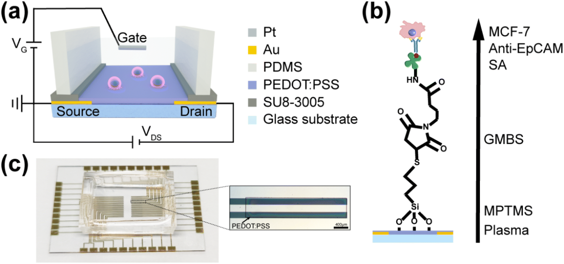 | ||
| Fig. 2 (a) The schematic diagram of a cell sensor based on a solution gated OECT. (b) The schematic diagram of anti-EpCAM antibody conjugation on PEDOT:PSS film for cancer cells capturing. (c) Optical micrograph of an OECT array device and an individual transistor. Scale bar is 400 μm. | ||
Fig. 2c shows a OECT array device prepared according to the procedure. The OECT array were fabricated on a 4 cm × 4 cm glass substrate. Under the optical microscope, the patterned gold electrodes and PEDOT:PSS films have clear edges and a uniform size, ensuring good consistency in the performance of each unit in the array. All of the OECTs can be characterized on the electrodes extended to the sides, so the excellent physical property of the PEDOT:PSS pattern can be confirmed by the measurement of the device performance. It is noteworthy that the PEDOT:PSS film has only been treated with acetone, therefore the surface of the film is clean and the conductivity is very high, which has been successfully used in the fabrication of OECT devices.42
Using plasma to increase the surface hydroxyl of the water-insoluble PEDOT:PSS layer allows us to attach anti-EpCAM to the surface of the OECT channel via silane. Fig. 2b shows the schematic diagram of grafting antibodies on PEDOT:PSS surface for MCF-7 cancer cells capturing. AFM and XPS were used to characterize the PEDOT:PSS film with and without the process of modifying the EpCAM antibody. As shown in Fig. S3a and b,† the roughness of the PEDOT:PSS film became smaller by about 20 nm after the modification steps, which indicated that the antibodies were successfully conjugated onto the film, which made the film a flatter surface. From Fig. S3c,† the survey scan XPS spectra of PEDOT:PSS film was attained. Elements such as C, N, O, S, Si were significantly increased when the PEDOT:PSS film was modified by antibody. As shown in Fig. S3d,† five main peaks with different intensities can be found form the C 1s deconvolution spectrum of the PEDOT:PSS, which illustrated the different chemical states of the PEDOT:PSS surface. The peaks observed at 283.8 eV, 284.8 eV, 286.3 eV, 286.02 eV and 288.6 eV were mainly belonged to C– Si bond, C–C/C–H bonds, C–N bond, C–O/C–S bonds, and C![[double bond, length as m-dash]](https://www.rsc.org/images/entities/char_e001.gif) O bond, respectively.43,44 Compared with the unmodified PEDOT:PSS, the signals of these peaks were significantly enhanced, indicating the success of specifical antibody modification.
O bond, respectively.43,44 Compared with the unmodified PEDOT:PSS, the signals of these peaks were significantly enhanced, indicating the success of specifical antibody modification.
Obviously, the capture efficiency of cancer cells related to the density of antibodies on the PEDOT:PSS surface and the incubation time of cells. The antibody density is directly related to the hydroxyl density of the surface caused by oxygen plasma treatment. The influence of plasma treatment time and cell incubation time on the cancer cells capture capacity were investigated. Firstly, 90 min is selected for cancer cells incubation time to ensure that all cancer cells were sedimentation on the PEDOT:PSS surface, to investigate the effect of oxygen plasma time on cell capture. As shown in Fig. 3a and S4,† it can be found that the efficiency of capturing MCF-7 cells was influenced by the oxygen plasma treatment time. When the PEDOT:PSS film was treated with oxygen plasma for 1.5 min, the efficiency of cell capture was the highest, about 80%. There had no obvious increase in the cell capture efficiency when the oxygen plasma treatment time increased. The reason may be due to the saturation of hydroxyl group when oxygen plasma treatment time was larger than 1.5 min. Therefore, in the following experiments, the PEDOT:PSS films of OECTs were all treated for 1.5 min during the specifical antibody modification. Since the cell sedimentation time may also affect the capture efficiency, the effect of cell capture time was also investigated. As shown in Fig. 3b and S5,† maximum capture efficiency can be achieved after 45 min incubation time for MFC-7.
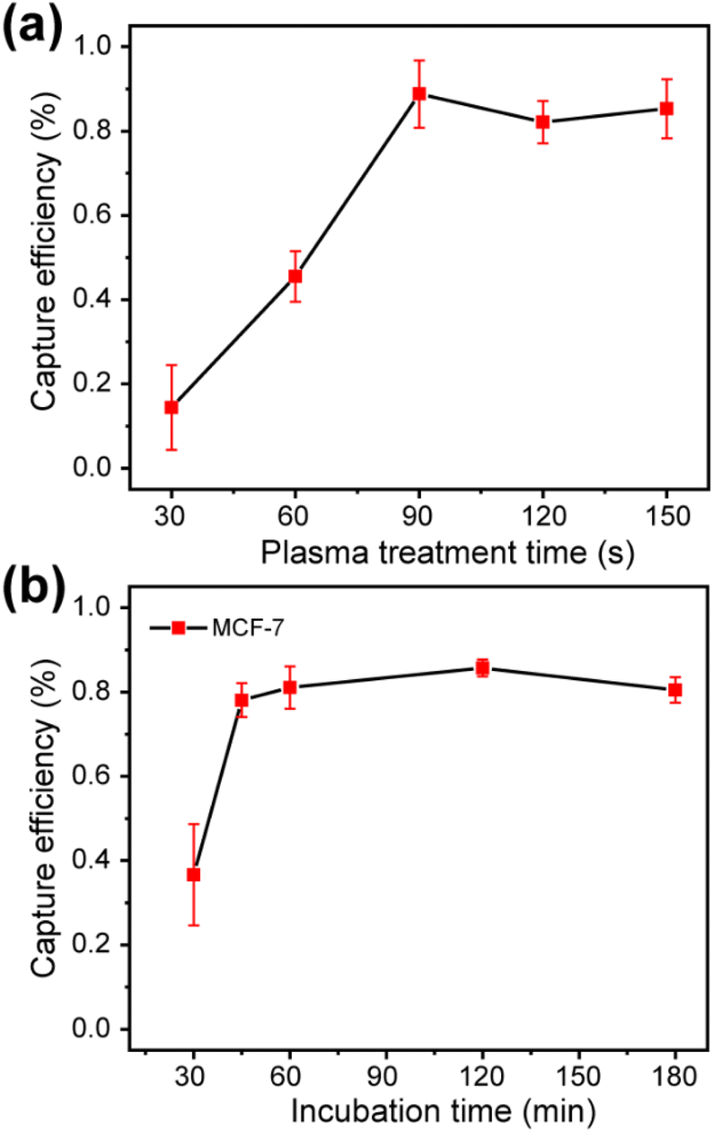 | ||
| Fig. 3 (a) The capture efficiency of MCF-7 cells on the PEDOT:PSS surface treated by oxygen plasma for different time. (b) The capture efficiency of MCF-7 cells on the PEDOT: PSS surface at different incubation time. | ||
3.2 The electric performance of OECT array
It is obviously that it is easy and highly integrated if Au electrode was selected as the gate voltage. However, the modulation capability of channel current of Au gate electrode was weaker than that of Pt gate electrode.45 As shown in Fig. S6,† the transfer characteristic curve and output characteristic curve had a small range of IDS modulated by the Au gate voltage, which will affect the sensitivity of the device. Therefore, Pt electrode was selected as the gate electrode in the following experiments. As shown in Fig. 4a, the transfer characteristic curves of a single OECT in PBS with an interval of 10 min. The results indicated that the transfer curves were repeatable and the channel current can be modulated from 105.4 μA to 5.6 μA when the gate voltage increased from 0 V to 1.0 V.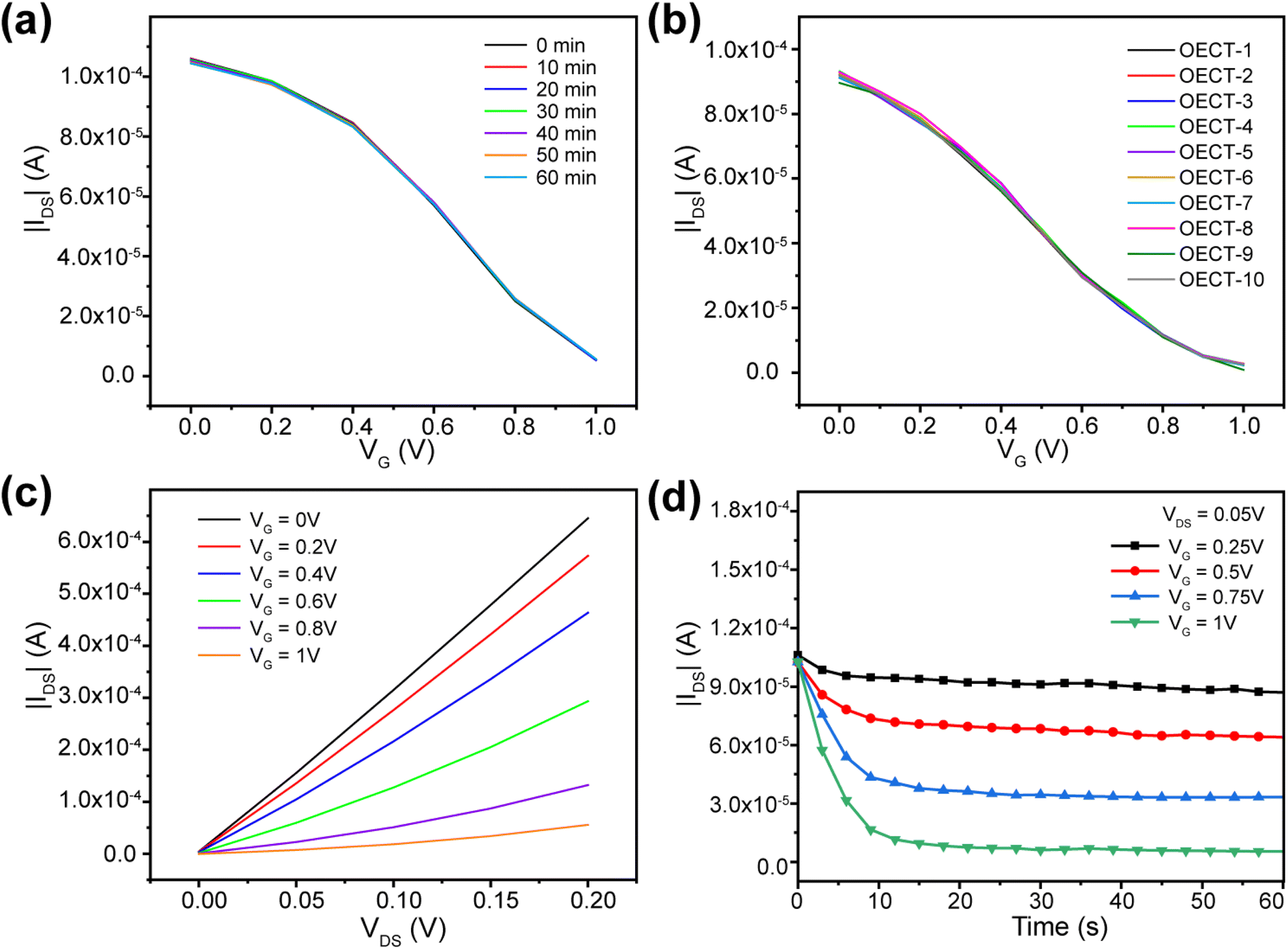 | ||
| Fig. 4 (a) Transfer characteristics of an OECT measured in PBS at different times within 1 h. (b) Transfer characteristics of different OECTs measured in PBS. (c) Output characteristics of an OECT. (d) The response of channel current of an OECT to the applied gate voltage. | ||
The electrical performance repeatability of each OECT in the array is important for the biosensor. As shown in Fig. 4b, transfer characteristic curves of 10 random OECT sensors in the OECT array were test. Ther results indicated that both the stability of a single device and the performance compatibility of different OECT units in the array manufactured using photolithography have a repeatability performance. The output characteristics was shown in Fig. 4c. Through the transfer and output characteristics, the channel current modulation is between 1–2 orders of magnitude with a gate voltage VG of 1 V. We also investigated the corresponding speed of the OECT devices to the applied gate voltage, as shown in Fig. 4d. The channel current can be stabilized within 10 s, which shows that there was not effect of photoresist on the electric performance of PEDOT:PSS film during the fabrication.
3.3 Cancer cells detection using OECT
It had been demonstrated that cancer cells morphology can be deformable corresponding to the environment.46 In order to investigate the feasibility of detecting cancer cells with OECT, the change of transfer curve during the cell capture progress was monitored. OECT was measured after the MCF-7 cell suspension was added on the device, and it was measured every 10 min for a period of 2 h.Fig. 5a shows the change of the transfer characteristic curve in 1 h. After the suspension was added for 10 min, the transfer curve showed a great shift to the positive gate voltage, which was attributed to the fact that cancer cells settled to the surface of PEDOT:PSS, and the change of the transfer curve tended to be stable when the capture time was more than 40 min, with a relatively stable bias of about 25 mV. The shift of transfer characteristic curve when the capture time was enlarged to 2 h was depicted in Fig. 5b. Through the change, it can be found that the transfer curve is shifted to negative voltage direction. The effective gate voltage shift within two hours is shown in Fig. 5c. The results indicated that the effective gate voltage shift was increased in the first 40 min and kept stable for 30 min and then shift to the negative direction. This may be related to the change of cancer cells morphology when the capture time was more than 1 h. Therefore, one hour of cell capture time can bring the most accurate signal changes.
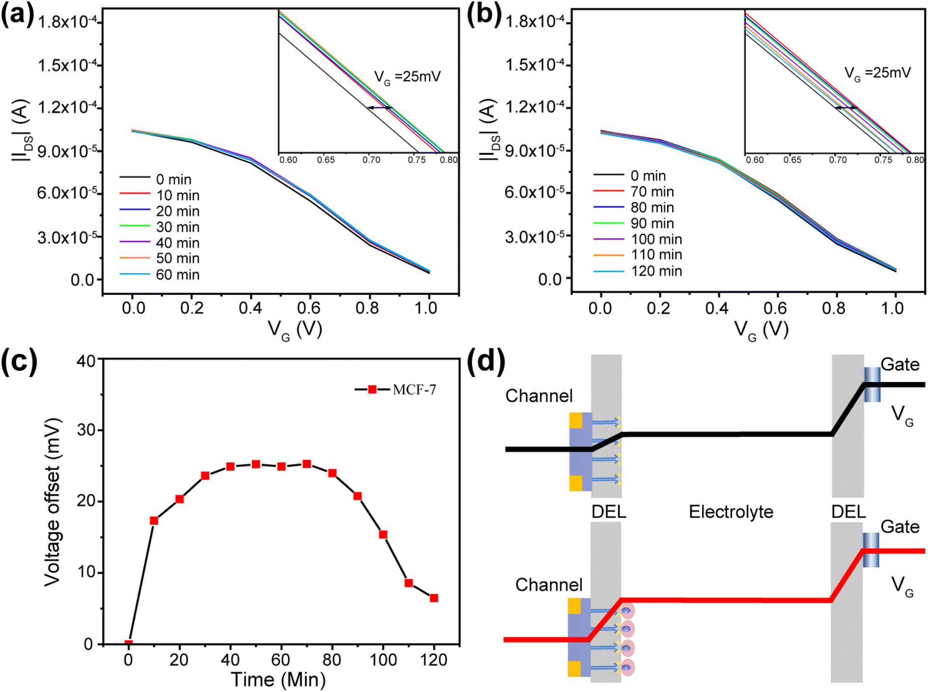 | ||
| Fig. 5 (a) Transmission characteristic change of an OECT when cell suspension is added within 1 h. (b) Transmission characteristic change of an OECT when cell suspension is added in 1 h to 2 h. (c) The gate voltage shifts and offsets the transfer curve corresponding to (a) and (b). (d) Schematic diagram of potential drops in the electric double layers (EDL), including the channel/electrolyte and electrolyte/gate interfaces, in the OECT before and after the capture of cells on the PEDOT:PSS surface. | ||
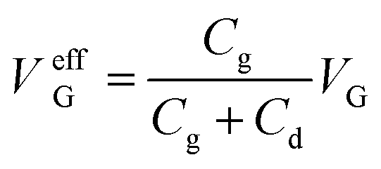
The transformation mechanism of OECT transfer characteristics is discussed. As shown in Fig. 5d, the gate voltage was applied on the two EDL, including the electrolyte/gate and electrolyte/PEDOT:PSS. The effective gate voltage (VeffG) applied on the channel is given by:21,41
 | (1) |
 | (2) |
The reversed gate voltage shift when the capture time was more than 1 h may be attributed to the deformable of cell morphology on the PEDOT:PSS surface, which prevents the direct ion exchange between PEDOT:PSS and the electrolyte and breaks the exchange equilibrium. The cancer cell morphology can be characterized by immunofluorescence stain, as shown in Fig. S7,† where F-actin and vinculin were stained by specific antibody. Compared to the cell morphology after captured for one hour, the contact between the cells and the interface was tighter after captured for two hours, and there were more cilia and microvilli around the cancer cells, which increased the contact area between the cells and the conductive film, and modulated the channel current of OECT.
3.4 OECT detection of cancer cells
Based on the selectivity and monitoring of cancer cells, OECTs biosensor can be used to detect different numbers of cancer cells. OECTs to the testbed as shown in Fig. S8,† where the device is connected to the Keithley 4200-SCS via a multiplexer controlled by customized software in a computer. Test by multiplexer can autonomously and quickly switch between different units in the OECTs, avoiding inaccurate data caused by long test intervals between different OECTs due to excessive manual operation time. The transfer properties of the antibody modified OECTs in PBS were test several times until stabilized to be used as a baseline. Next, control the number of cells captured by the device by calculating the preparation of different specific concentrations of MCF-7 suspensions (in PBS). After adding the cell suspension for 1 h, the uncaptured cells were eliminated, and the transfer characteristics were tested. As shown in Fig. 6a, the transfer curve shifted to a higher positive gate voltage when the number of captured cells increased. Fig. 6b shows the dependence between the effective gate voltage offsets and the number of captured cells. In this work, the detectable number of cells was only a few hundred, and the design of the array avoids the error generated by the test and has higher sensitivity. As shown in Fig. S9,† when the concentration of cancer cells increased to 5000, cells captured by the OECT may cover the entire PEDOT:PSS surface, and the effective gate voltage shift was about 63 mV. This shift voltage was closed to the average zeta potential of the cells, which is consistent with the previous reports.48,49 Therefore, the OECTs can be used as sensitive biosensors for cancer cells detection.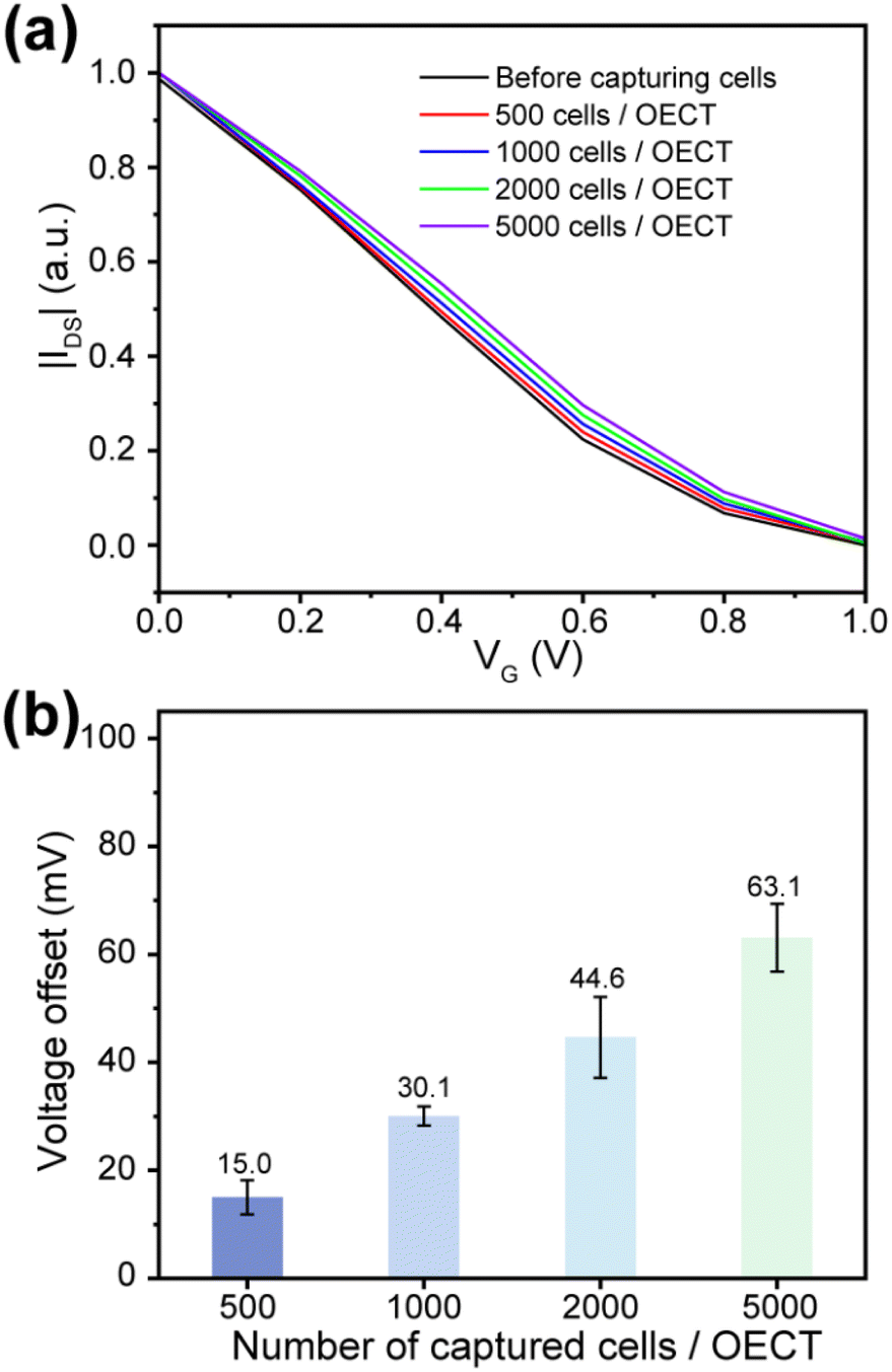 | ||
| Fig. 6 (a) Transfer characteristics of OECT after cancer cells capturing at different concentration. (b) The effective gate voltage shifts of OECT after cancer cells capturing at different concentration. Error bars represent the error for the effective gate voltage shifts of different OECTs on the same OECT array. | ||
4. Conclusions
In this work, OECT array was fabricated with a convenient, repeatable method. The active layer of OECTs were patterned through photolithography without affecting their electric performance. The PEDOT:PSS-based solution gated OECTs had been successfully used as biosensors for cancer cells detection, which were specifical captured on the surface of conductive film. Due to the electrostatic interaction between the cells and the PEDOT:PSS layer, the transfer curve of OECT shifted toward a higher gate voltage after the cells were captured. This method can provide new insights to improve the accuracy of the OECTs-based method and show a wider application prospect of array devices. To optimize the sensor, devices and methods with higher resolution should be design and developed to shrink the channel area. Therefore, OECT arrays with smaller channel area and more transistors will be necessary to reduce the lower limit of cell number detection and achieve single-cell high-throughput detection in the future.Author contributions
Qingyuan Song, Weiyi Wang and Jinjin Liang performed the experiments; Qingyuan Song and Chaohui Chen contributed to the data analysis; Yiping Cao and Bo Cai helped with the methodology; Qingyuan Song and Rongxiang He wrote the manuscript; Bo Cai and Bolei Chen revised the manuscript; Rongxiang He was responsible for the conceptualization and supervised the work.Conflicts of interest
There are no conflicts to declare.Acknowledgements
This work was supported by the National Natural Science Foundation of China (Grant No. 81741019) and the Wuhan Municipal Science and Technology Bureau (Applied Foundation Frontier Project, No. 2019020701011440). The authors also acknowledge the financial support from the Youth Talent Support Program of Jianghan University.Notes and references
- A. Marks, S. Griggs, N. Gasparini and M. Moser, Adv. Mater. Interfaces, 2022, 9, 2102039 CrossRef CAS.
- A. Nawaz, Q. Liu, W. L. Leong, K. E. Fairfull-Smith and P. Sonar, Adv. Mater., 2021, 33, 2101874 CrossRef CAS PubMed.
- Y. Yao, W. Huang, J. Chen, X. Liu, L. Bai, W. Chen, Y. Cheng, J. Ping, T. J. Marks and A. Facchetti, Adv. Mater., 2023, 35, 2209906 CrossRef CAS PubMed.
- D. Khodagholy, J. Rivnay, M. Sessolo, M. Gurfinkel, P. Leleux, L. H. Jimison, E. Stavrinidou, T. Herve, S. Sanaur, R. M. Owens and G. G. Malliaras, Nat. Commun., 2013, 4, 2133 CrossRef PubMed.
- J. Rivnay, S. Inal, A. Salleo, R. M. Owens, M. Berggren and G. G. Malliaras, Nat. Rev. Mater., 2018, 3, 17086 CrossRef CAS.
- Y. Fang, X. M. Li and Y. Fang, J. Mater. Chem. C, 2015, 3, 6424–6430 RSC.
- M. Berggren and A. Richter-Dahlfors, Adv. Mater., 2007, 19, 3201–3213 CrossRef CAS.
- K. Feron, R. Lim, C. Sherwood, A. Keynes, A. Brichta and P. C. Dastoor, Int. J. Mol. Sci., 2018, 19, 2382 CrossRef PubMed.
- R. B. Rashid, X. D. Ji and J. Rivnay, Biosens. Bioelectron., 2021, 190, 113461 CrossRef CAS PubMed.
- J. Ajayan, P. Mohankumar, R. Mathew, L. R. Thoutam, B. K. Kaushik and D. Nirmal, IEEE Trans. Electron Devices, 2023, 70, 3401–3412 CAS.
- X. Strakosas, M. Bongo and R. M. Owens, J. Appl. Polym. Sci., 2015, 132, 41735 CrossRef.
- M. Sensi, G. Migatti, V. Beni, T. M. D'Alvise, T. Weil, M. Berto, P. Greco, C. Imbriano, F. Biscarini and C. A. Bortolotti, Macromol. Mater. Eng., 2022, 307, 2100880 CrossRef CAS.
- C. H. Chen, Q. Y. Song, W. T. Lu, Z. T. Zhang, Y. H. Yu, X. Y. Liu and R. X. He, RSC Adv., 2021, 11, 37917–37922 RSC.
- N. X. Wang, A. N. Yang, Y. Fu, Y. Z. Li and F. Yan, Acc. Chem. Res., 2019, 52, 277–287 CrossRef CAS PubMed.
- L. M. Bai, C. G. Elosegui, W. Q. Li, P. Yu, J. J. Fei and L. Q. Mao, Front. Chem., 2019, 7, 313 CrossRef CAS PubMed.
- Y. Y. Liang, A. Offenhaeusser, S. Ingebrandt and D. Mayer, Adv. Healthcare Mater., 2021, 10, 2100061 CrossRef CAS PubMed.
- A. Nawaz, Q. Liu, W. L. Leong, K. E. Fairfull-Smith and P. Sonar, Adv. Mater., 2021, 33, 2101874 CrossRef CAS PubMed.
- L. V. Lingstedt, M. Ghittorelli, M. Bruckner, J. Reinholz, N. I. Craciun, F. Torricelli, V. Mailander, P. Gkoupidenis and P. W. M. Blom, Adv. Healthcare Mater., 2019, 8, 1900128 CrossRef PubMed.
- K. Lieberth, P. Romele, F. Torricelli, D. A. Koutsouras, M. Bruckner, V. Mailander, P. Gkoupidenis and P. W. M. Blom, Adv. Healthcare Mater., 2021, 10, 2100845 CrossRef CAS PubMed.
- F. Hempel, J. K. Y. Law, T. C. Nguyen, R. Lanche, A. Susloparova, X. T. Vu and S. Ingebrandt, Biosens. Bioelectron., 2021, 180, 113101 CrossRef CAS PubMed.
- P. Lin, F. Yan, J. J. Yu, H. L. W. Chan and M. Yang, Adv. Mater., 2010, 22, 3655–3660 CrossRef CAS PubMed.
- O. Salyk, J. Vitecek, L. Omasta, E. Safarikova, S. Stritesky, M. Vala and M. Weiter, Appl. Sci., 2017, 7, 998 CrossRef.
- C. Alix-Panabieres and K. Pantel, Cancer Discovery, 2016, 6, 479–491 CrossRef CAS PubMed.
- D. H. Moon, D. P. Lindsay, S. Hong and A. Z. Wang, Adv. Drug Delivery Rev., 2018, 125, 143–150 CrossRef CAS PubMed.
- J. X. Yin, J. Q. Deng, L. Wang, C. Du, W. Zhang and X. Y. Jiang, Anal. Chem., 2020, 92, 6968–6976 CrossRef CAS PubMed.
- K. Tsuji, H. M. Lu, J. K. Tan, H. Kim, K. Yoneda and F. Tanaka, Mobile Netw. Appl., 2020, 25, 1042–1051 CrossRef.
- X. Yin, B. B. Chen, M. He and B. Hu, Anal. Chem., 2020, 92, 10308–10315 CrossRef CAS PubMed.
- X. Zhang, X. Wei, X. Men, C. X. Wu, J. J. Bai, W. T. Li, T. Yang, M. L. Chen and J. H. Wang, ACS Appl. Mater. Interfaces, 2021, 13, 43668–43675 CrossRef CAS PubMed.
- F. Zhang, L. L. Wu, W. D. Nie, L. L. Huang, J. F. Zhang, F. Li and H. Y. Xie, Anal. Chem., 2019, 91, 15726–15731 CrossRef CAS PubMed.
- A. Wu, A. A. Bhagat, M. C. Leong and C. T. Lim, J. Clin. Oncol., 2014, 32, e22023 Search PubMed.
- X. Zhu, Y. Z. Suo, Y. T. Fu, F. L. Zhang, N. Ding, K. Pang, C. Y. Xie, X. F. Weng, M. L. Tian, H. He and X. B. Wei, Light Sci. Appl., 2021, 10, 110 CrossRef CAS PubMed.
- R. Pilot, R. Signorini, C. Durante, L. Orian, M. Bhamidipati and L. Fabris, Biosensors, 2019, 9, 57 CrossRef CAS PubMed.
- X. R. Li and Y. G. Zhou, Electrochem. Commun., 2021, 124, 6 CrossRef.
- J. K. Y. Law, A. Susloparova, X. T. Vu, X. Zhou, F. Hempel, B. Qu, M. Hoth and S. Ingebrandt, Biosens. Bioelectron., 2015, 67, 170–176 CrossRef CAS PubMed.
- T. A. Burinaru, B. Adiaconita, M. Avram, P. Preda, A. M. Enciu, E. Chiriac, C. Marculescu, T. Constantin and M. Militaru, Mater. Today Commun., 2022, 32, 104016 CrossRef CAS.
- X. H. Zhang, X. J. Jiang, W. Wang, S. H. Luo, S. J. Guan, W. B. Li, B. Situ, B. Li, Y. Zhang and L. Zheng, Microchim. Acta, 2023, 190, 65 CrossRef CAS PubMed.
- L. Ding, W. Cheng, X. J. Wang, S. J. Ding and H. X. Ju, J. Am. Chem. Soc., 2008, 130, 7224–7225 CrossRef CAS PubMed.
- M. Zhang, P. Lin, M. Yang and F. Yan, Biochim. Biophys. Acta, Gen. Subj., 2013, 1830, 4402–4406 CrossRef CAS PubMed.
- S. Y. Yang, J. A. DeFranco, Y. A. Sylvester, T. J. Gobert, D. J. Macaya, R. M. Owens and G. G. Malliaras, Lab Chip, 2009, 9, 704–708 RSC.
- N. Wang, Y. Liu, Y. Fu and F. Yan, ACS Appl. Mater. Interfaces, 2018, 10, 25834–25840 CrossRef CAS PubMed.
- R. X. He, M. Zhang, F. Tan, P. H. M. Leung, X. Z. Zhao, H. L. W. Chan, M. Yang and F. Yan, J. Mater. Chem., 2012, 22, 22072–22076 RSC.
- L. Z. Chen, Y. Fu, N. X. Wang, A. N. Yang, Y. Z. Li, J. Wu, H. X. Ju and F. Yan, ACS Appl. Mater. Interfaces, 2018, 10, 18470–18477 CrossRef CAS PubMed.
- E. Desimoni and B. Brunetti, Chemosensors, 2015, 3, 70–117 CrossRef CAS.
- J. Haque, V. Srivastava, D. S. Chauhan, M. A. Quraishi, A. Madhan Kumar and H. Lgaz, Sustainable Chem. Pharm., 2020, 16, 100260 CrossRef.
- P. Lin, F. Yan and H. L. W. Chan, ACS Appl. Mater. Interfaces, 2010, 2, 1637–1641 CrossRef CAS PubMed.
- H. N. Liu, M. L. Ruan, J. R. Xiao, Z. T. Zhang, C. H. Chen, W. Y. Zhang, Y. P. Cao, R. X. He, Y. M. Liu and Y. Chen, ACS Appl. Mater. Interfaces, 2018, 10, 66–74 CrossRef CAS PubMed.
- M. Thompson, L.-E. Cheran, M. Zhang, M. Chacko, H. Huo and S. Sadeghi, Biosens. Bioelectron., 2005, 20, 1471–1481 CrossRef CAS PubMed.
- D. Q. Lin, L. N. Zhong and S. J. Yao, Biotechnol. Bioeng., 2006, 95, 185–191 CrossRef CAS PubMed.
- Y. Zhang, M. Yang, J. H. Park, J. Singelyn, H. Q. Ma, M. J. Sailor, E. Ruoslahti, M. Ozkan and C. Ozkan, Small, 2009, 5, 1990–1996 CrossRef CAS PubMed.
Footnote |
| † Electronic supplementary information (ESI) available. See DOI: https://doi.org/10.1039/d3ra06800e |
| This journal is © The Royal Society of Chemistry 2023 |