
 Open Access Article
 This Open Access Article is licensed under a Creative Commons Attribution-Non Commercial 3.0 Unported Licence
Repair of soft magnetic properties of wasted silicon steel and Co7Fe3 alloy deposition mechanism
Hongxuan Xinga,
Jidong Li *a,
Xianwei Hub,
Yaowu Wangb,
Yiyong Wanga and
Zhipeng Lianga
*a,
Xianwei Hub,
Yaowu Wangb,
Yiyong Wanga and
Zhipeng Lianga
aSchool of Materials and Metallurgy, University of Science and Technology Liaoning, Anshan 114051, China. E-mail: xhx17070958303@163.com; lijidong1014@163.com
bNortheastern University, School of Metallurgy, Shenyang 110000, China
First published on 15th November 2023
Abstract
In order to repair the soft magnetic properties of wasted silicon steel, a theoretical process of co-depositing Co–Fe soft magnetic alloy on the surface of wasted silicon steel is proposed. The results show that the co-deposited Co–Fe alloy coatings can serve to repair the soft magnetic properties of wasted silicon as detected by the vibrating sample magnetometer, and the alloy coatings with Co7Fe3 as the main phase structure can provide surface protection for silicon steel. Subsequently, the mechanism of co-deposited Co–Fe alloys was investigated, and it was concluded that Co2+ and Fe2+ undergo a one-step two-electron co-deposition reaction, as studied using cyclic voltammetry. The chronoamperometric analysis and its fitting results indicated that the deposition of Co2+ and Fe2+ was a diffusion-controlled transient nucleation process, and the AC impedance indicated that higher voltages were favorable for the deposition of Co–Fe alloys but were accompanied by hydrogen precipitation reactions.
1. Introduction
Countries around the world encourage the application of renewable resources and improve the efficiency of energy and resource utilization, which is of great significance to the healthy development of the economy.1 Silicon steel is the core component of the core in transformers and the production is increasing day by day. The long-term operation and use of harsh environment not only decrease the quality of the silicon steel surface, such as silicon steel sheet surface rust, holes, and scratches butt also lead to a decline in the soft magnetic properties of silicon steel, such as saturation magnetic induction strength decline, hysteresis loss increase, coercive force increases and many other damages.2 The decline in performance results in the wastage of silicon steel resources, and the large market and high profits have made countries around the world worry about the sustainable development of waste silicon steel and its corrosion resistance.3In previous studies, researchers treated wasted silicon steel by recycling and remelting it, resulting in a huge waste of human and ore resources.4 Some wasted silicon steel is simply painted and reused, which brings serious safety hazards to transformers, mainly in the form of increased hysteresis loss, increased temperature rise, and easy breakdown of the core.5 In addition, most of the researchers are focusing on the study of silicon steel coated with insulating paint and the study of magnesium silicate base layer covered on the surface of the silicon steel.6,7 Before the silicon steel is coated with insulating paint, it will be exposed to an uncontrollable environment, which greatly increases the risk of being corroded. It is therefore crucial to propose a process that can both repair the soft magnetic properties of the wasted silicon steel and enhance the corrosion resistance of the original silicon steel.
Pornthep Chivavibul et al.8 proposed to electrodeposit Ni–Co–P coating on the surface of silicon steel and studied the effect of different thicknesses of the coating on the hysteresis loss of silicon steel, and it was found that Ni–Co–P coating reduced the hysteresis loss by 4%; however, the effect of the alloy on other soft magnetic properties and corrosion resistance was not reported. Vishu Goel et al.9 coated Co–Ni–P on the surface of the oriented silicon steel and reduced the hysteresis loss by approximately 9% and noted that depositing cobalt-based alloys on the surface of silicon steel helps enhance the soft magnetic properties and reduce the hysteresis loss. Ferromagnetic transition metals, such as Fe, Co, and Ni show the saturation magnetization of 251, 177, and 54.39 emu g−1,6 respectively, thus Co–Fe alloys can form coatings with the highest saturation magnetization strength. Chansena10 obtained Co–Fe alloy by electrodeposition on the surface of the copper substrate and investigated the effect of iron content on corrosion resistance, showing that the alloy has the best performance when the iron content is 37% and the cobalt content is 63%. Therefore, in this paper, we propose a process of electrodeposition of Co–Fe alloy on the surface of wasted silicon steel to repair the soft magnetic properties and improve the corrosion resistance of the wasted silicon steel, which provides a new idea for the comprehensive utilization of silicon steel resources in the future. In addition, we studied the electrochemical deposition behavior of the Co–Fe alloy, which is an important component of the magnetic head in disks, and revealed the deposition mechanism of the Co–Fe alloy to provide theoretical guidance for the electrochemical synthesis of other alloys.
2. Materials and methods
2.1 Preparation of Co–Fe alloys
Wasted silicon steel substrates (1 cm2) and asbestos sheet (2 cm2) were wet polished with SiC paper grade 400, 800, 1200, 1500, and 2000. The substrates were cleaned with surfactant and rinsed with deionized water. They were finally sonicated in isopropyl alcohol for 5 min and dried with hot air prior to further electrodeposition. The bath electrolyte was purged with nitrogen gas for 30 min before electrodeposition. The Co–Fe alloy was deposited by electrodeposition (Fig. 1). The types of reagents and their dosages are listed in Table 1.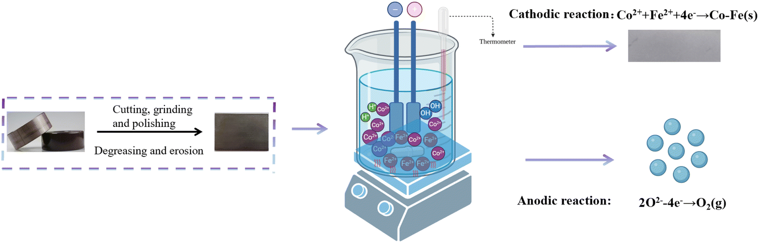 | ||
| Fig. 1 Co-deposition of Co–Fe alloy coating process flow chart. | ||
| Categories | Co–Fe | Prerequisite |
|---|---|---|
| Composition of the plating solution | CoSO4·7H2O | 20 g L−1 |
| FeSO4·7H2O | 10 g L−1 | |
| NaB4O7·10H2O | 20 g L−1 | |
| C4H4Na2O6 | 45 g L−1 | |
| MgSO4 | 0.4 g L−1 | |
| C12H25SO3Na | 0.05 g L−1 | |
| Process parameters | Current density | 300 mA cm−2 |
| pH | 7 | |
| Temperature | 40 °C | |
| Times | 60 min |
2.2 Surface characterization
A Sigma 500 scanning electron microscope (SEM) was used to observe the surface morphology of the sample, and a Bruker energy dispersive spectrometer (EDS) was used to analyse the chemical composition or elemental distribution of the coated sample. X-ray diffraction (XRD) tests were carried out on different coatings using an Ultam IV X-ray diffractometer from Rigaku, Japan, with CuKα1 radiation, a wavelength λ of 0.15405 nm, X-ray tube voltage of 40 kV, tube current of 20 mA, scanning rate of 40° min−1, and scanning range (2θ) of 30° to 90°. The magnetic properties were determined using a vibrating sample magnetometer (VSM).2.3 Electrochemical testing
In the mechanistic tests, the Ag/AgCl electrode was used as a reference. The platinum plate was a counter electrode (1 cm2) and the wasted silicon steel was a working electrode with an exposure area of 4 cm2.For the corrosion tests, the corrosion solution used in previous studies was the NaCl solution with a mass fraction of 3.5%, but the working environment of the silicon steel of the transformer core was air or a harsh acidic environment.10 The corrosion solution we selected was a vented acidic solution (HCl) with pH values of 3, 4, and 5, and vented deionized water, in order to simulate the actual production and storage environment and to ensure that the saturation of oxygen The reference electrode was an Ag/AgCl electrode, the auxiliary electrode was a platinum sheet with stable performance, and the working electrode was coated with Co–Fe alloy.
3. Results and discussion
3.1 Characterization of Co–Fe alloy
As shown in Fig. 2(a), XRD peaks appeared at approximately 2θ = 45° and 2θ = 83°, and the main composition is Co7Fe3, and no separate diffraction peaks for pure metal Co and Fe were observed, and the positions of their strong peaks were very close to each other, so it can be assumed that there were no separate phases of Co and Fe during the plating. The lattice constants of Co7Fe3 a = 2.8403 Å, b = 2.8403 Å, c = 2.8403 Å, α = β = γ = 90° belong to the cubic crystal system. In addition, the cross-section analysis showed that the Co–Fe alloy coating thickness was less than 25 μm, which met the requirement of less than 100 μm thickness for the silicon steel protective coatings.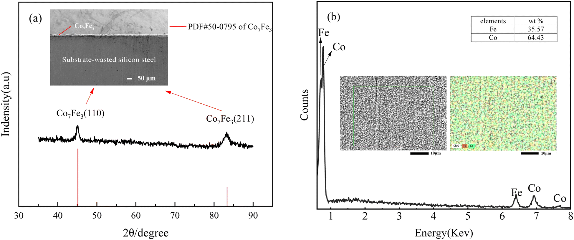 | ||
| Fig. 2 Surface charaterization: (a) the XRD and SEM cross-section of alloy coatings; (b) the EDS of alloy coatings. | ||
The resulting micro-morphology of the plated layer and the distribution of Co and Fe in the plated layer are shown in Fig. 2(b). The surface of the coating was extremely dense, and the two elements of Co and Fe were uniformly distributed on the surface of the coating. There were no cracks on the surface of the plated layer, and the plated layer was not peeled off or damaged after repeated adhesion of the high-adhesive PET tape, and the bonding force was good. In addition, Co and Fe contents were 64.43% and 35.57%, respectively, reaching the optimum soft magnetic elements content described in the literature.7
3.2 Soft magnetic performance repair
Electrodeposition of Co–Fe alloy on the surface of waste silicon steel could repair the soft magnetic properties,11,12 Co–Fe alloy is a layer of coating that can increase the magnetic conductivity of silicon steel and improve its soft magnetic properties. In addition, after a period of time, the wasted silicon steel will have microcracks, grain growth, grain boundary segregation, and other problems, resulting in a decline of the soft magnetic properties. Electrodeposited Co–Fe alloy can fill these microscopic defects in the process of coating formation, repair the structure of silicon steel, and improve its soft magnetic properties. In addition, according to the research of Zhang Y. et al.,13 the cobalt content in Co–Fe alloy plays a dominant role in the soft magnetic properties, and when the cobalt content reaches 64%, the Co–Fe alloy can achieve the most excellent soft magnetic properties; as such in this study, we chose the process with a cobalt content up to 64% to perform the soft magnetic restoration of wasted silicon steel (Fig. 3).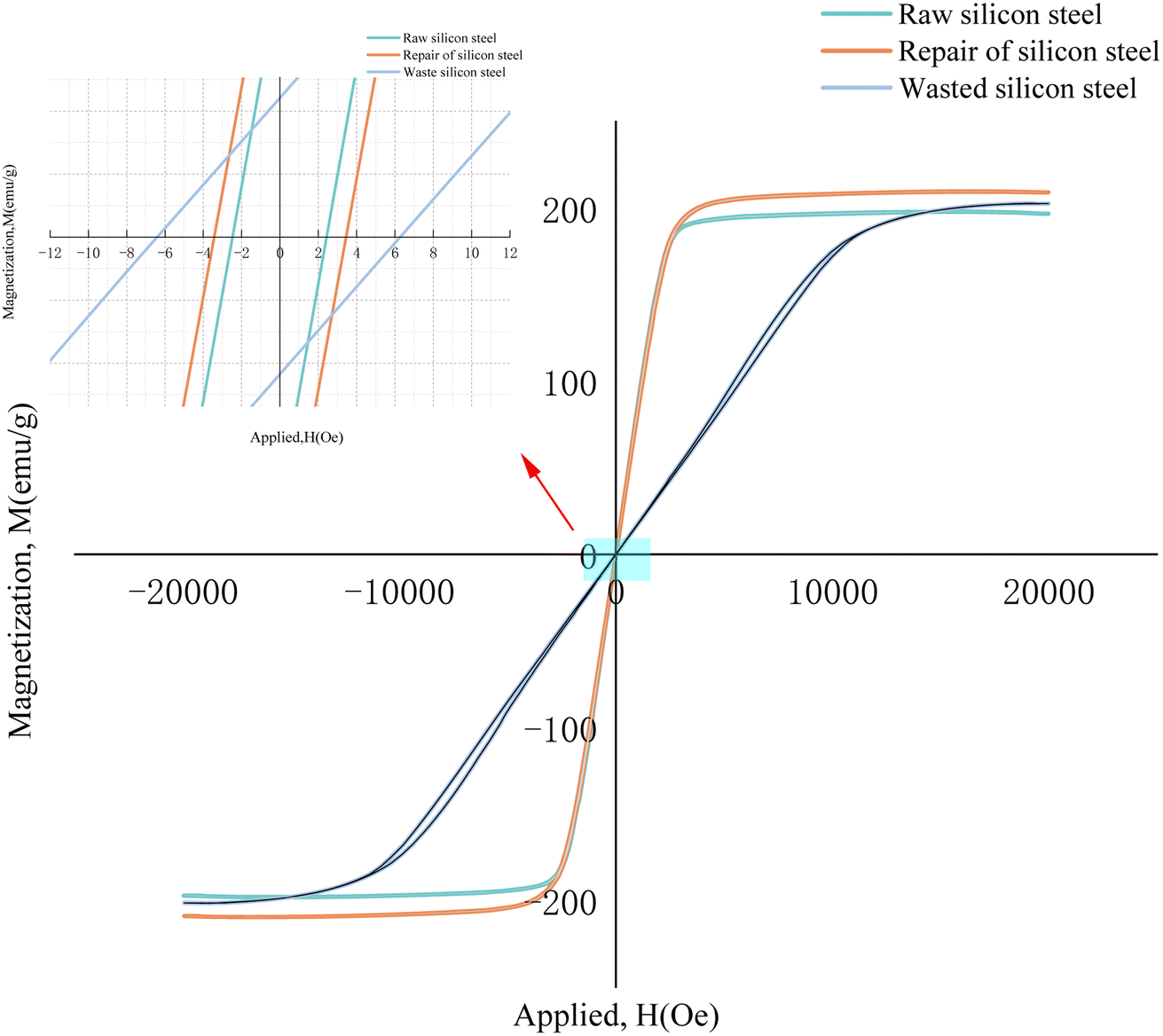 | ||
| Fig. 3 Hysteresis loop of different samples. | ||
The soft magnetic properties of the different samples are shown in Fig. 6. It can be seen that compared to the original silicon steel, the coercivity (Hc) of the wasted silicon steel has a significant elevation, and its magnetization speed also decreases significantly, and the saturation magnetization decreases. After plating repairs, the coercivity (Hc) of the silicon steel was significantly reduced, the magnetization speed was significantly increased, and the saturation magnetization (Ms) was also enhanced to some extent. The specific performance enhancement is shown in Table 2, after adding the Co–Fe coating, the saturation magnetization (Ms) increased by 6.25%, the coercivity (Hc) decreased by 43.5%, and the soft magnetic performance was significantly improved, indicating that the Co–Fe alloy coating played a regenerative role in repairing the waste silicon steel.
| Title | Ms (emu g−1) | Hc (Oe) | Ms (aise) (%) | Hc (recovery) (%) |
|---|---|---|---|---|
| Wasted silicon steel | 202.761 | 6.2 | — | — |
| Raw silicon steel | 196.769 | 2.5 | — | — |
| Repair of the silicon steel | 209.071 | 3.5 | 6.25% | 43.5% |
3.3 Corrosion testing
As can be seen from Table 3, the corrosion current density of the Co7Fe3 alloy increases by an order of magnitude (10−6 increases to 10−5) when the pH decreases by one unit, and the increase in corrosion current density indicates a higher risk from the corrosion point of view. After the pH is less than 4, the order of magnitude of the corrosion current density will no longer change. It is important to note that the pH of deionized water cannot generally be measured with a pH electrode due to its extremely low conductivity. In any case, if the deionized water is in contact with the atmosphere during the manufacturing process in a clean room, the pH can be slightly below 7 and corrosion may occur more rapidly as gas absorption proceeds.13| Corrosion solution | Jcorr (A cm−2) | Ecorr (V) | Corrosion rate (mm per year) |
|---|---|---|---|
| Deionizes water | 1.92 × 10⁻⁷ | −0.424 | 2.23 × 10⁻³ |
| pH 3 | 4.81 × 10⁻⁵ | −0.557 | 5.59 × 10⁻¹ |
| pH 4 | 1.83 × 10⁻⁵ | −0.557 | 2.13 × 10⁻¹ |
| pH 5 | 2.86 × 10⁻⁶ | −0.549 | 3.32 × 10⁻² |
| Silicon steel (pH 5) | 6.99 × 10⁻⁶ | −0.561 | 8.14 × 10⁻² |
Based on the corrosion rate values obtained from Fig. 4 and Table 3, the corrosion rates were analyzed based on previous literature.14 In general, metallic materials with corrosion rates below 0.1 mm per year are considered corrosion resistant, while corrosion rates above 0.1 mm per year are classified as non-corrosion resistant.15 According to these criteria, the Co7Fe3 alloy can be considered corrosion resistant in aerated pH 5 solution and in aerated deionized water. In addition to this, it can be seen from the graph shows that the dynamic potential polarization curve of the Co7Fe3 alloy coating does not show a passivation zone that inhibits the occurrence of corrosion.
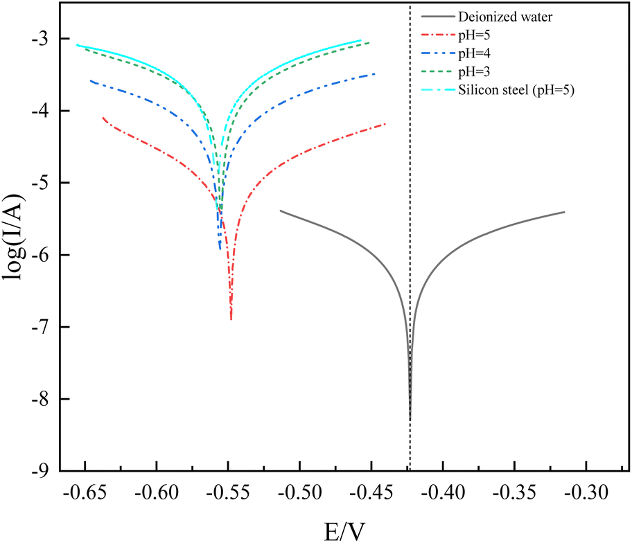 | ||
| Fig. 4 Polarization curve test of Co7Fe3 alloys under deionized water and different pH solutions. | ||
3.4 Mechanism of electrodeposited Co–Fe alloy
 | ||
| Fig. 5 Cyclic voltammetry curve at the Fe electrode for Co–Fe alloys. | ||
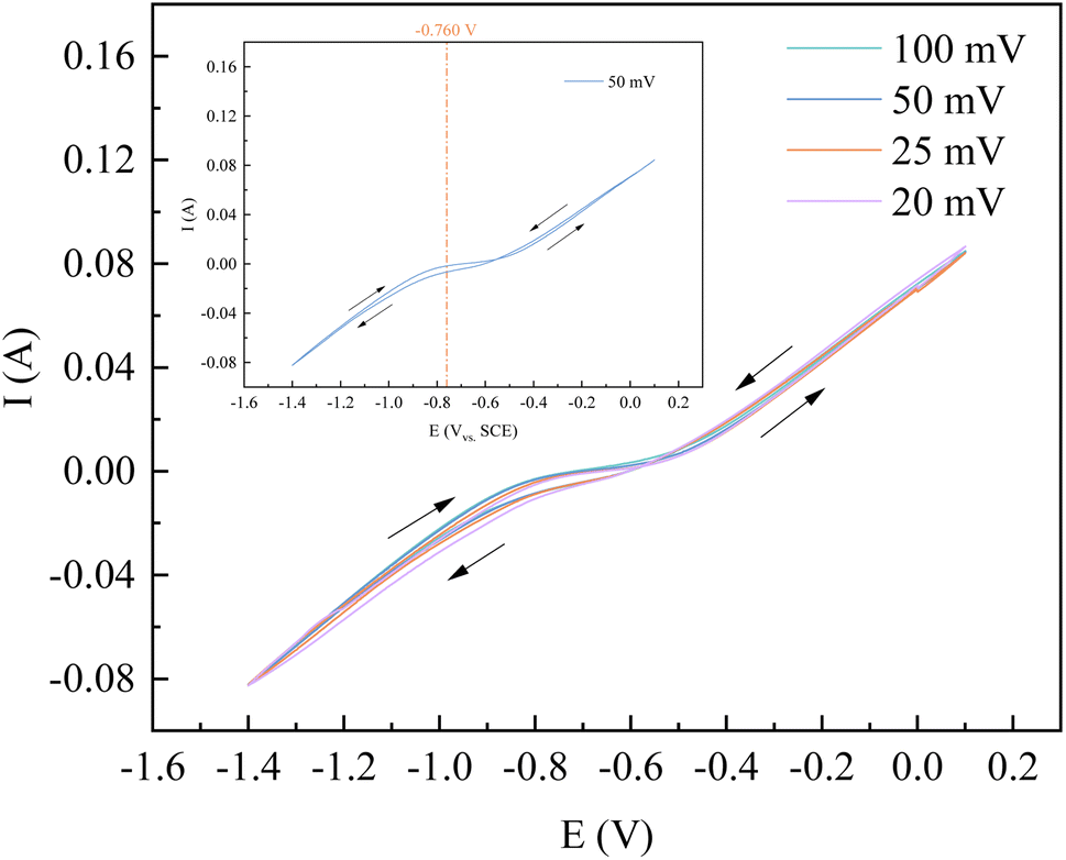
Take the example of a sweep rate of 50 mV s−1 in CV for the relevant calculations. In the CV curves of the mixed FeSO4–CoSO4 solution, a rapid change in current again at −0.760 V, but after −0.760 V without the presence of a reduction peak or a rapidly changing position of the current. Since the deposition potential of Co2+ is lower than that of Fe2+, it can be considered that the induced co-deposition occurred at −0.760 V.1 In order to further verify the number of electrons transferred during the reduction of Co2+, and Fe2+ on the silicon steel electrode, any four points on the left side of −0.760 V were taken, and the relevant data were calculated and tabulated, as shown in Table 4 and Fig. 6.
| Ip/mA | I/mA | E/V | lg[(I − Ip)/I] |
|---|---|---|---|
| −6.528 | −6.747 | −0.765 | −1.488 |
| −6.528 | −6.860 | −0.768 | −1.315 |
| −6.528 | −6.973 | −0.771 | −1.195 |
| −6.528 | −7.086 | −0.773 | −1.104 |
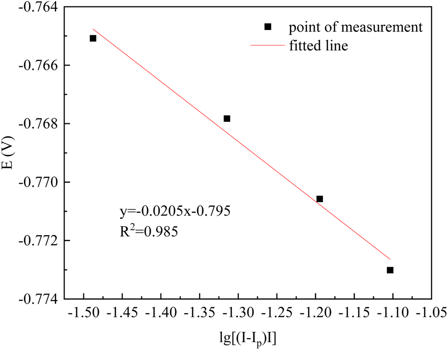 | ||
| Fig. 6 Fitted line about E–lg[(I − Ip)/I] diagram (25 mV s−1). | ||
As can be seen in Fig. 6, the E–lg[(Ip − I)/I] curve is linear with the slope of the fitted straight line K = 0.0205. According to the Nernst eqn (1) for the number of transferred electrons:16
 | (1) |
The slope K = 1.857RT/nF = 0.0205, from which the CV curve at −0.760 V for 50 mV s−1 corresponds to the number of electrons transferred:
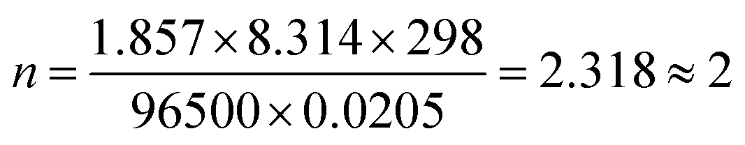
It is proven that the electron transfer number at −0.760 V is 2. The principle is as follows: Fe2+ + 2e−→Fe. In addition, according to the deposition potential of Co2+, the following reaction also takes place: Co2+ + 2e− → Co. It can be seen that the induced co-deposition of Co and Fe occurs at −0.670 V.
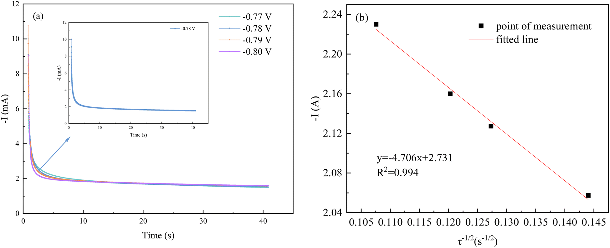 | ||
| Fig. 7 Chronoamperometric analysis: (a) chronoamperometry under different potentials; (b) fitted line about −I–τ−1/2. | ||
When different step potentials are applied, the current increases to an enormous maximum due to the bilayer charging effect. After that, the current decreases with time from the moment of energization due to the migration effect of ions to the cathode and finally slows down to reach the steady state current value, which indicates that the crystal growth and nucleation process occurs at this stage.17 In an aqueous solution, the ion concentration is much larger than the cathode surface, at this time the electrode surface concentration polarization dominates. Due to the difference in ion concentration, eventually, the two regions reach an ideal equilibrium and the current no longer changes.
The diffusion coefficient of Co2+ and Fe2+ was calculated according to Cotrell's equation.17
 | (2) |
From Fig. 7(b), it is known that the transition time τ−1/2 in the timing current shows a good linear relationship with the current intensity, which proves that the electrochemical reduction process of Co2+ and Fe2+ on the cathode surface is controlled by the diffusion step. According to eqn (2), the diffusion coefficients of Co2+ and Fe2+ can be calculated. Combining the known data, including the working electrode surface area, S = 4 cm2, Iτ1/2 = 4.706 mA s1/2, F = 96![[thin space (1/6-em)]](https://www.rsc.org/images/entities/char_2009.gif) 485C mol−1, C0–Co2+ = 0.071 mol L−1 and C0–Fe2+ = 0.036 mol L−1, n = 2, π = 3.14, DCo2+ = 0.939 × 10⁻⁸ cm2 s−1 and DFe2+ = 3.651 × 10⁻⁸ cm2 s−1 were obtained.
485C mol−1, C0–Co2+ = 0.071 mol L−1 and C0–Fe2+ = 0.036 mol L−1, n = 2, π = 3.14, DCo2+ = 0.939 × 10⁻⁸ cm2 s−1 and DFe2+ = 3.651 × 10⁻⁸ cm2 s−1 were obtained.
The nucleation mode of Co2+ and Fe2+ at the deposition potential can be obtained by selecting different points from the stages of chronoamperometric curves and fitting them according to eqn (4) and (6).18
Instantaneous nucleation:
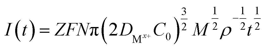 | (3) |
 | (4) |
Continuous nucleation:
 | (5) |
 | (6) |
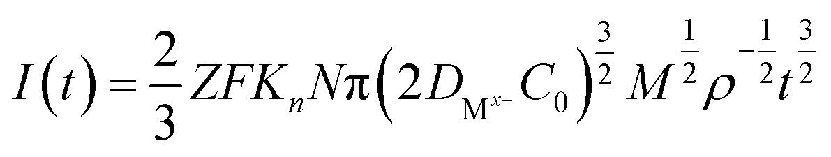
500 C mol−1; N-the nucleation number density/cm−2; DMx+-diffusion coefficient/cm2 s−1; C0-concentration of Co2+ or Fe2+/mol L−1; M-molar mass/g mol−1; ρ-density/g cm−3; Kn-nucleation rate constant/cm−2 s−1; t-time/s; and π = 3.14.
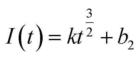
Instantaneous nucleation and continuous nucleation equations can be fitted from four different points arbitrarily taken from the rising portion of the different timing current curves in Fig. 8. The degree of fit between I(t) − t1/2 and I(t) − t2/3 is listed in Table 5.
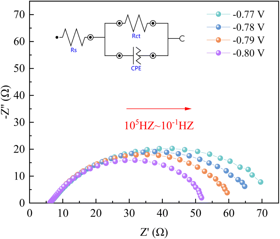 | ||
| Fig. 8 Nyquist plots of the data obtained on the silicon steel electrode. | ||
| E/V | I(t) − t1/2 degree of fitting | I(t) − t3/2 degree of fitting |
|---|---|---|
| −0.77 | 0.990 | 0.988 |
| −0.78 | 0.988 | 0.985 |
| −0.79 | 0.984 | 0.981 |
| −0.80 | 0.987 | 0.982 |
Table 5 shows that the fitting degree of I(t) − t1/2 is better than the fitting degree of I(t) − t3/2 at any potential, which indicates that the nucleation mechanism of Co2+ and Fe2+ on the silicon steel plate is instantaneous nucleation.18
| E/V | Rs/Ω | Rct/Ω |
|---|---|---|
| −0.77 | 6.27 | 70.2 |
| −0.78 | 6.24 | 63.6 |
| −0.79 | 6.23 | 57.1 |
| −0.80 | 6.21 | 48.7 |
As can be seen from Fig. 8, when the applied potential is −0.77–−0.80 V, the Nyquist pattern of the Co–Fe system basically exhibits a complete capacitive arc semicircle. With the increase of the applied voltage, the arc radius gradually decreases, indicating that the increase of the voltage can rapidly reach the activation energy required for the reaction, reduce the charge transfer resistance, and accelerate the process of the electrochemical reaction.19,20 In addition, we also found some scattering points at the end of the arc, which are related to the hydrogen precipitation reaction.
4. Conclusions
Based on the repair of soft magnetic properties of wasted silicon steel and the mechanism of Co–Fe alloy deposition, the following conclusions can be obtained:(1) By co-depositing the Co7Fe3 alloy coating on the surface of the wasted silicon steel, the coercivity of the waste silicon steel was reduced by 43.5% and its saturation magnetization strength was increased by 6.25%, which realized the repair of the soft magnetic properties as well as the high-value recycling of the wasted silicon steel. In addition, the corrosion current density of the Co7Fe3 alloy coating was 1.92 × 10⁻⁷ A cm−2, which enhanced the protection of the substrate and avoided the secondary damage to the repaired silicon steel.
(2) The electrodeposition mechanism of the Co–Fe alloys revealed that Co2+ and Fe2+ in the sodium tartrate system is a diffusion-controlled transient nucleation process, with diffusion coefficients of 0.939 × 10⁻⁸ cm2 s−1 and 3.651 × 10⁻⁸ cm2 s−1, respectively. The AC impedance revealed that applying a higher voltage is favorable to the metal nucleation but causes the current efficiency to become low. The study of the electrochemical behavior of Co–Fe alloys provides theoretical guidance for the electrochemical synthesis of other alloys.
Conflicts of interest
All authors disclose no relevant relationships.Acknowledgements
Thanks for the financial help provided by the Key Laboratory of Metallurgical Engineering of Provincial Universities and Colleges (2023KFKT-10). Supported by the National Nature Science Foundation of China (52374352).References
- H. Kang, J. Li and C. Zhang, et al., Study of the electrochemical recovery of cobalt from spent cemented carbide, RSC Adv., 2020, 10(37), 22036–22042 RSC.
- K. M. Liew and A. Akbar, The recent progress of recycled steel fiber reinforced concrete, Constr. Build. Mater., 2020, 232, 117232 CrossRef.
- J. Guo, Y. Bao and M. Wang, Steel slag in China: Treatment, recycling, and management, Waste Manage., 2018, 78, 318–330 CrossRef PubMed.
- S. PIROMRAK, P. JANTARATANA and C. SIRISATHITKUL, Magnetic Properties of Cobalt-coated Silicon Steels Prepared by Electrodeposition, Walailak J. Sci. & Tech., 2007, 4(1), 123–138 Search PubMed.
- C. Sirisathitkul, S. Piromrak and P. Jantaratana, Magnetoimpedance of cobalt-coated silicon steels, Phys. B, 2011, 406(2), 155–158 CrossRef CAS.
- Y. Liu, L. Wu and A. Chen, et al., Component Design of Environmentally Friendly High-Temperature Resistance Coating for Oriented Silicon Steel and Effects on Anti-Corrosion Property, Coatings, 2022, 12(7), 959 CrossRef CAS.
- Y. Zhang, H. Gu and S. Yang, et al., Improved magnetic properties of grain-oriented silicon steel by in-situ formation of potassium zirconium phosphate in insulating coating, J. Magn. Magn. Mater., 2020, 506, 166802 CrossRef CAS.
- P. Chivavibul, M. Enoki and S. Konda, et al., Application of electroless-plated magnetic coating to reduce core loss of electrical steel, Adv. Mater. Res., 2010, 117, 21–25 CAS.
- V. Goel, P. Anderson and J. Hall, et al., Application of Co–Ni–P coating on grain-oriented electrical steel, IEEE Trans. Magn., 2015, 52(4), 1–8 Search PubMed.
- A. Chansena and S. Sutthiruangwong, Corrosion behavior of electrodeposited Co-Fe alloys in aerated solutions, J. Magn. Magn. Mater., 2017, 429, 251–256 CrossRef CAS.
- J. M. Silveyra, E. Ferrara and D. L. Huber, et al., Soft magnetic materials for a sustainable and electrified world, Science, 2018, 362(6413), eaao0195 CrossRef PubMed.
- Z. Huang, L. Wu and Y. Liu, et al., Preparation and Properties of Oriented Silicon Steel Insulation Coating with Repair Function, J. Phys.: Conf. Ser., 2020, 1637(1), 012045 CrossRef CAS.
- Y. Zhang and D. G. Ivey, Electrodeposition of nanocrystalline CoFe soft magnetic thin films from citrate-stabilized baths, Mater. Chem. Phys., 2018, 204, 171–178 CrossRef CAS.
- D. R. Unune, G. R. Brown and G. C. Reilly, Thermal based surface modification techniques for enhancing the corrosion and wear resistance of metallic implants: A review, Vacuum, 2022, 111298 CrossRef CAS.
- S. Naghdi and V. Mišković-Stanković, A review of the corrosion behaviour of graphene coatings on metal surfaces obtained by chemical vapour deposition, J. Electrochem. Soc., 2022, 169(2), 021505 CrossRef CAS.
- Z. Hou, X. Wang and J. Li, et al., Electrochemical Mechanism of the Preparation of High-Purity Indium by Electrodeposition, Front. Chem., 2022, 10, 871420 CrossRef CAS PubMed.
- H. Xing, Z. Li and E. Feng, et al., Mechanism of Tungsten Recovery from Spent Cemented Carbide by Molten Salt Electrodeposition, J. Electrochem. Sci. Technol., 2023, 14(1), 75–84 CrossRef CAS.
- Z. Hou, J. Li and X. Wang, et al., Effect of Tin Ion on Electrodeposition Behavior of Indium, Electrochemistry, 2022, 90(8), 087007 CrossRef CAS.
- S. Donkor, Z. Song and L. Jiang, et al., An overview of computational and theoretical studies on analyzing adsorption performance of phytochemicals as metal corrosion inhibitors, J. Mol. Liq., 2022, 359, 119260 CrossRef CAS.
- N. R. N. Masdek, W. M. A. Aiman and M. C. Murad, et al., The effect of saccharin concentration on the electrochemical behaviour of electrodeposited nanocrystalline cobalt-iron coating, Pertanika J. Sci. & Technol., 2017, 25, 191–200 Search PubMed.
| This journal is © The Royal Society of Chemistry 2023 |