
 Open Access Article
 This Open Access Article is licensed under a Creative Commons Attribution-Non Commercial 3.0 Unported Licence
Bubble formation phenomenon on the absorber column for CO2 absorption and to produce precipitated silica sodium carbonate
Srie Muljani *a,
Heru Setyawanb and
Reva Edra Nugrahaa
*a,
Heru Setyawanb and
Reva Edra Nugrahaa
aDepartment of Chemical Engineering, Faculty of Engineering, Universitas Pembangunan Nasional “Veteran” Jawa Timur, Surabaya 60294, Indonesia. E-mail: sriemuljani.tk@upnjatim.ac.id
bDepartment of Chemical Engineering, Faculty of Industrial Technology and System Engineering, Kampus ITS Sukolilo, Surabaya 60111, Indonesia
First published on 15th November 2023
Abstract
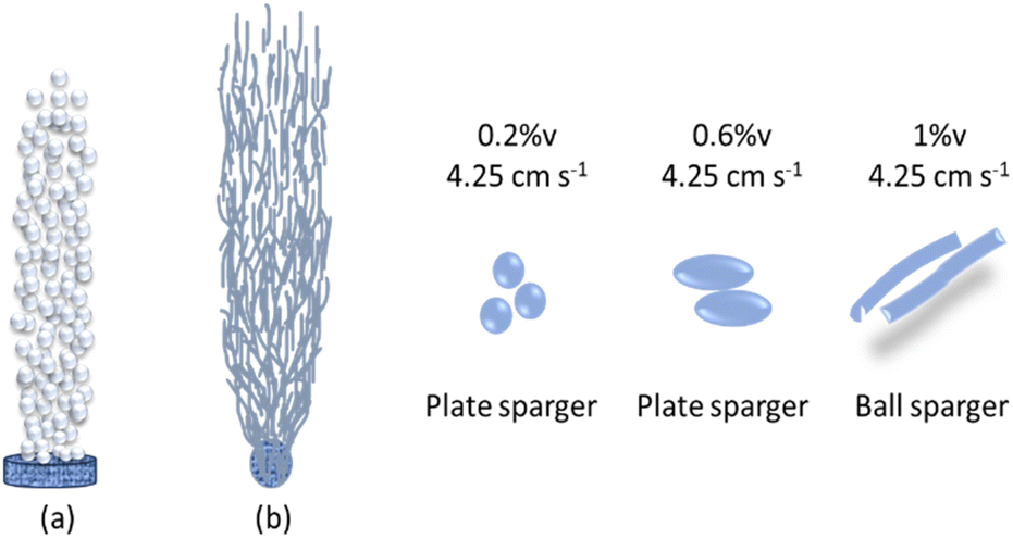
CO2 absorption using sodium silicate aqueous solution in a bubble column has been studied. Sodium silicate aqueous solutions are classified as non-Newtonian fluids that can affect the bubble distribution. The goal of this research is to investigate the effect of a superficial gas velocity (0.85 cm s−1, 2.55 cm s−1, and 4.25 cm s−1) and sodium silicate concentration (0.2% v, 0.6% v, and 1.0% v) on the phenomenon formation of spherical-bubbles, ellipsoidal-bubble, and rod-shape bubbles in bubble column. The experiment was carried out in one minute interval during the five minutes operation. The CO2 absorption and the gel formation is influenced by the pH of the solution where the gas holdup plays an important role in changing the pH. The characterization of the precipitated particles showed that the trona phase (C2H5Na3O8) reached 88% in the preparation of 1% aqueous sodium silicate at a superficial gas velocity of 4.25 cm s−1. The superficial velocity of the gas and the concentration of the sodium silicate solution influence the formation of bubbles. Spherical bubbles and ellipsoidal bubbles were observed in CO2 absorption experiments using a plate sparger, while rod-shaped bubbles were observed in experiments using a ball sparger.
Introduction
Bubbles play an important role in the design of both the reactor and the absorber. Bubble dynamics are generally affected by the viscosity of the liquid.1 High-viscosity systems are rarely studied for their bubble behavior, which is often involved in relevant industrial processes.2 Thus the gas distributor has an important role in the evolution of the bubble size distribution in the gas–liquid reactor, stripper, and absorber.3 The mesh type bubble breaker was found to be effective in reducing the size of nozzle generated bubbles in co-current two-phase vertical flow.4 As reported by Dong et al., the number of bubbles in the liquid and the gas holdup are influenced by the superficial velocity of the gas.5 It was also reported that the residence time of bubbles in the aqueous solution and the bubble diameter distribution were influenced by the concentration (w%) of the aqueous solution. In this experiment, the phenomenon of bubble formation was observed due to changes in superficial gas velocity and changes in concentration of silicate aqueous solution as a viscous solution. Based on the gas velocity there were three regimes. The homogeneous regimes were defined for uniform bubble size and bubble distribution in the axial and radial directions of the column. Heterogeneous regimes are developed when the gas flow rate increases rapidly, characterized by the presence of a wide bubble size distribution that agglomerates due to the high gas flow velocity.6 Turbulent or slug churn flow was found in the third regime that occurs at high gas flow rates. In this regime the fusion forms gas bubbles whose size is compared to the diameter of the reactor.7 As they move through the column, there is an intermittent outflow of gases and liquids.7 The type of regime in the bubble column reactor affects the conversion and selectivity directly.8 CO2 absorption has been developed using various methods and various solvents, and various studies related to gas bubbles in liquid solvents.4,5,9–11 The CO2 is captured via chemisorption in a slurry bubble column with a liquid phase made up of an organic solution mixture of methanol or alcohol as a solvent.9 The product of this chemisorption process is a solid that can be filtered, in contrast if the sodium silicate aqueous solution is used as a solvent which produces a gel from the CO2 absorption process. The carbonization method, commonly known as the carbon fraction method, is a method of producing silicic acid by acidifying a sodium silicate solution with CO2.12 The stages of silica gel formation include hydrolysis, polymerization and growth. Polymerization is the nucleation stage in which silicon–oxygen bonds are formed from oligomers of silicic acid molecules, which then agglomerate after reaching the critical diameter. In this study, the absorption of CO2 into sodium silicate aqueous solution (Na2SiO3) as a solvent may be influenced by the pH of the solution so that the high gas holdup is unnecessarily proportional to high CO2 uptake. Likewise, if the distributed gas bubbles are small in size, this has no guarantee that CO2 can be absorbed properly. On the other hand, sodium silicate aqueous solvent was quite viscous so that the bubbles generated in the column could affect the gas holdup and pH of the bulk liquid. In this regard, it is necessary to study the performance of bubble columns in absorbing CO2 with several limiting factors that need to be considered, including the bubbles created, gas holdup, liquid pH, liquid residence time and gel formation in the column, which are influenced by superficial gas velocity and solvent concentration. The absorption of CO2 into an aqueous sodium silicate solution follows the reaction| Na2SiO3(aql) + CO2(g) → Na2CO3 + SiO2 | (1) |
In addition to sodium carbonate (Na2CO3), the presence of H2O allows the formation of trona (Na3H(CO3)2(H2O)2). The mixture of Na2CO3 and SiO2 products is in the liquid phase, which will eventually turn into a soft solid (gel) if the pH conditions are favorable. Silica gel apart from a network of individual molecular chains (polymer gel) is also formed from a collection of larger molecules (colloidal gel).13,14 Absorption of CO2 into the aqueous solutions of sodium silicate is likely to reduce the viscosity of the solution as the pH of the solution decreases.13 The gel formation process occurs through the reaction of siloxane bond formation, –Si–OSi– from sodium silicate.15
| Na2SiO3 + xH2O + 2H+ → SiO2 (x + 1) H2O + 2Na+ | (2) |
Based on this reaction, it can be stated that gel formation depends on the pH or concentration of protons [H+] in the solution. The lower the pH, the higher the [H+] in the sodium silicate solution and some of the siloxy groups (Si–O–) form silanol groups (Si–OH). The appearance of H+ protons in contact with CO2 will temporarily form carbonic acid and cause acidification of the aqueous sodium silicate solution. Under basic conditions, all the silica in solution exists as silicate ions, SiO3![[double bond, length as m-dash]](https://www.rsc.org/images/entities/char_e001.gif) , and the Si atom is involved in electron delocalization with the O atom so that it is quite stable and it is difficult to form siloxane bonds.
, and the Si atom is involved in electron delocalization with the O atom so that it is quite stable and it is difficult to form siloxane bonds.
Determining the residence time of the liquid in semi-batch operations is important, because basically the volume of the feed liquid remains relatively unchanged, but the rheology changes as CO2 absorption into the liquid increases. Rheological changes are related to gel formation, where the viscosity of the liquid increases as the polymer chain increases, which will inhibit the absorption process and bubble formation.5 However, by controlling the gas velocity and using a bubble breaker, it is expected that the bubbles formed will be even in size, shape, and distribution in the sodium silicate aqueous solution. CO2 nanobubbles generated were in the range of 200–500 nm depending on the gas pressure, gas and water flow rate used.16 Ohde et al. reported that during CO2 saturation of the aqueous triethanolamine, bubble size distributions changed according to the level of CO2 saturation.17 In this research, two types of spargers (plate sparger and ball sparger) were used to study the distribution of the bubbles created, in addition to observing the characteristics of the deposited particles to determine the component phases and their morphology. The application of silica sodium carbonate as a green catalyst is reported to be very efficient and recyclable. Silica sodium carbonate has several advantages over the others, such as excellent product yield, short reaction time, environment friendly and safe procedures, easy handling and reuse of the catalyst.18,19
Experimental
Materials
Sodium silicate (Na2SiO3) aqueous solution was prepared by diluting waterglass 22.9% (Rm = 3.3, pH = 12.2, and density of 1.34) in the concentration range of 0.2, 0.4, 0.6, 0.8, and 1% v.CO2 absorption on the bubble column
5 kg carbon dioxide (CO2) gas cylinders were provided by SG Industry, Indonesia, with a pressure of 1200–1500 psi and a purity of 99.99%. The gas flowing from them is regulated by a pressure regulator and CO2 flow meter so that it forms bubbles through the micropore sparger. The bubble column (Fig. 1) with a height of 100 cm, and an outside diameter of 6.5 cm is equipped with a pH controller and a porous plate micropore stone as a bubble breaker (60 mm in diameter and 15 mm thick). The micropore ball stone sparger WS011 is available with a diameter of 4 cm. The column contains 3 L sodium silicate aqueous solution, where the liquid height reaches 85 cm. Superficial gas velocity is in the range of 0.85 cm s−1, 2.55 cm s−1 and 4.25 cm s−1. The operation takes place at atmospheric pressure and room temperature in a semi-batch manner with a liquid operation time of 5 min. Observations are made with a video camera with a horizontal distance to the bubble column of 250 mm, and the camera lens is focused on the vertical plane in the middle of the bubble column. This study chose the distribution of bubble sizes in each treatment in an area as high as 20 cm in the middle of the column and in two pH zones, namely before saturation and during saturation with an operating time of 5 minutes. Bubble size was determined using ImageJ. Gas holdup (εg) can be determined from the equation εg = 1 − (Hi/Hf) where Hi is the initial height of the liquid and Hf is the height of the liquid when gas bubbles flow from the bottom of the column.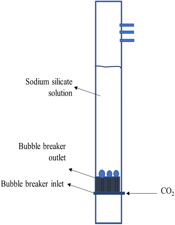 | ||
| Fig. 1 The bubble breaker diagram. | ||
The experiment was conducted at different sodium silicate aqueous solution concentrations and superficial gas velocities, as shown in Table 1.
| Code | Sodium silicate concentration (%) | Superficial gas velocity (cm s−1) |
|---|---|---|
| A | 0.2 | 0.85 |
| B | 0.2 | 2.55 |
| C | 0.2 | 4.25 |
| D | 0.6 | 0.85 |
| E | 0.6 | 2.55 |
| F | 0.6 | 4.25 |
| G | 1 | 0.85 |
| H | 1 | 2.55 |
| I | 1 | 4.25 |
Characterization of precipitated particles
The gel product (precipitated particles) was dried in a 100 °C oven for 24 h and ground into a powder and XPert-MPD diffractometer system, 30 mA, 40 kV with PANalytical measurement. The scanning range for measurement was 10–60°. XRD pattern analysis was performed to determine the polymorph phase using the Rietveld method with the X'PERT HIGHSCORE PLUS application. Matching XRD patterns from samples with XRD patterns from the JCPDS/ICDD database includes crystal system data, space groups, lattice parameters, atomic positions and the peaks of diffraction patterns. SEM images were obtained from an SU3500, which operates at low vacuum, 7 nm SE Image resolution at 3 kV, and 10 nm BSE image resolution at 5 kV. CO2 absorbed was observed from the presence of trona compounds in the precipitated particles.Bubble size measurement
Measurements of bubble size were conducted to ascertain how sodium silicate concentration, pH and sparger affected the bubble size. With the use of a video recorder, video clips were taken, and the bubbles on each frame of the recordings were examined. The images were examined using ImageJ software to determine bubble size distribution (100 visible bubbles were quantified from different parts of the image).Crystallite size measurement
The silica crystallite size was calculated using the Debye Scherrer equation (eqn (3)) based on XRD data at 2θ = 10–65° and FWHM (full width at half maximum) value as β.
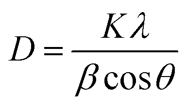 | (3) |
The Scherrer equation measures the crystal grain size, while the particle size is determined from the results of SEM image characterization using ImageJ.
Results and discussion
Effect of superficial gas velocity on bubbles and pH for 5 min operation time
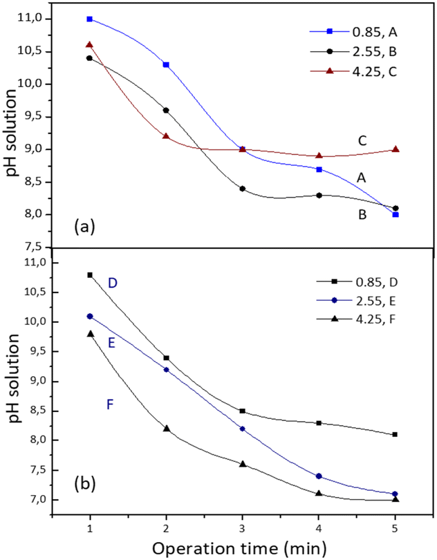
Observations on the pH and bubbles created were carried out at the same time for each experiment in a one minute interval during the five minute operation. The final pH is considered the pH for the aging stage. The aqueous sodium silicate solution initially has an average pH of 12 (acidification) due to the formation of carbonic acid during the CO2 absorption process. Based on height, the column was divided into three parts: the bottom (5 cm from the base), the middle (45 cm from the base), and the top (75 cm from the base). The pictures of all the experiment were used to determine the bubble size distribution, as shown in Fig. 2 (sodium silicate aqueous solution 1% v, superficial gas velocity 2.55 cm s−1).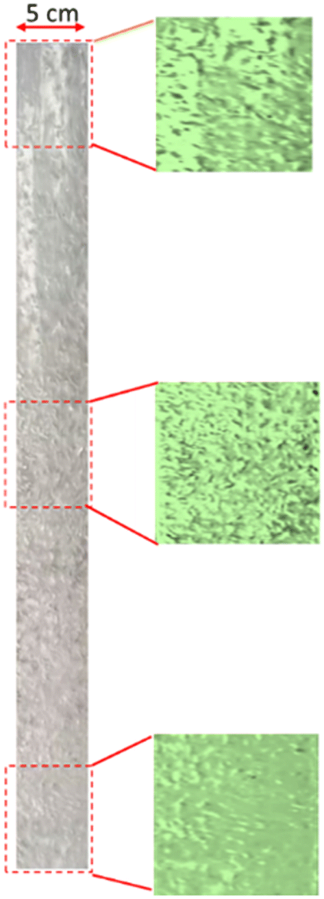 | ||
| Fig. 2 The bubble formation in the bubble column at different heights using 1% v sodium silicate solution and 2.55 cm s−1. | ||
Absorption operations for experiments A, B and C were carried out at the same concentration (0.2% v) but the superficial gas velocity increased from 0.85 to 4.25 cm s−1. Observations of pH during the 5 min operation time showed a relatively similar trend for experiments A and B, where the pH decreased quite sharply after 3 minutes of operation (Fig. 3). The average bubble size in experiment A was 0.016 cm at pH 10, increasing to an average size of 0.03 cm at the final pH 8, as shown in Fig. 4a and b. Based on previous research, equilibrium is reached at neutral pH (pH 7), where the silicate solution begins to undergo a condensation reaction accompanied by changes in viscosity.14 This can also be seen from the surface of the liquid at the top of the column with an inner diameter of 5 cm, which shows small bubbles (0.03–0.05 cm) that are evenly distributed. This regime is in accordance with a spherical shape at low Reynolds numbers (Re ≈ 1).20 Observations of pH in experiment C with high superficial gas velocity (4.25 cm s−1) showed slightly lower pH changes but the distribution and size of the bubbles were more even than in experiments A and B. In the second minute, a pH of 10.8 was observed with an average bubble size of 0.036 cm and reached the final pH value of 9 with a mean bubble size of 0.43 cm. Uniform and homogeneous bubbles should support a good absorption process because their mass transfer surface is quite large. Possibly due to the low silica concentration and excess CO2 (the CO2 bubbles are quite dense) the formation of carbonic acid has been unable to acidify the solution to a neutral pH. On the other hand, under alkaline conditions the SiO bonds are very strong so it is difficult to form siloxane.15
 | ||
| Fig. 3 The pH profile at different operation times from sodium silicate concentrations of 0.2% (a) and 0.6% (b) using a plate sparger. | ||
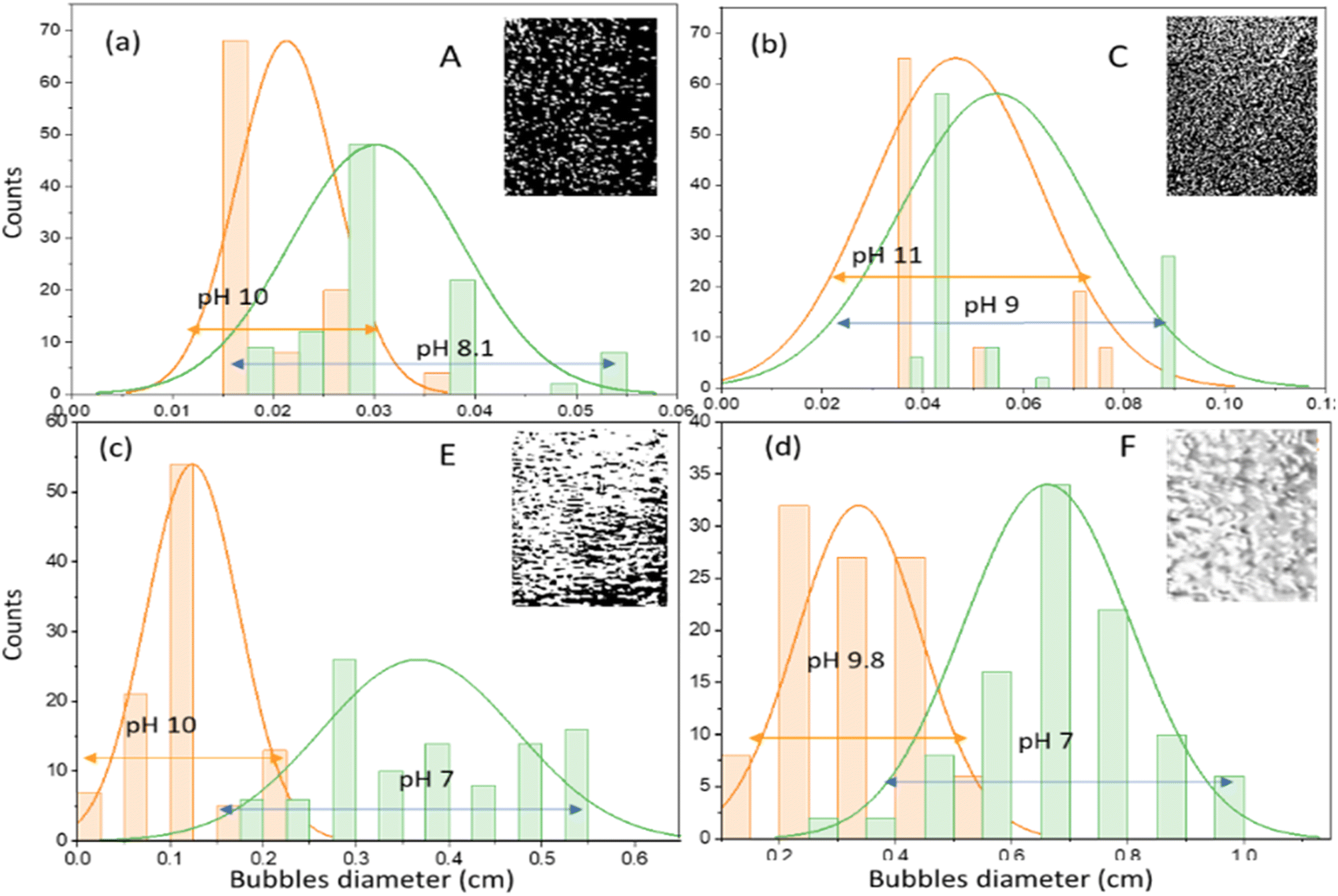 | ||
| Fig. 4 Bubble size distributions during initial saturation (pH 9–12) and at saturation (pH 7–8) of experiments A (a), C (b), E (c) and F (d). | ||
A similar phenomenon was also observed in experiment D; even though there was an increase in the concentration of aqueous sodium silicate solution (0.6% v) with a superficial gas velocity of 0.85 cm s−1, the final pH only reached a value of 8. In this case the gas velocity created macro bubbles with an average diameter of 0.17 cm. The changes are quite significant when the superficial velocity of the gas increases. Observations at pH 10 for experiment E showed that gas bubbles with a mean diameter of 0.122 cm flow smoothly to the surface of the liquid. The bubbles begin to enlarge due to the coalescence effect and become closer together as the pH decreases. The pH decreased to a value of 7 with the bubble distribution dominated by ellipsoidal bubbles with an elongated diameter of 0.28 cm (Fig. 4c). At pH 8 to pH 7 almost the entire column contains ellipsoidal bubbles. Fig. 4d shows the distribution of bubbles for experiment F at pH 9.8 have mean bubble diameter of 0.37 cm and at the final pH (pH 7) the mean ellipsoidal bubble size is 0.7 cm. The shape of bubbles with Reynolds numbers between 1 and 100 (1 < Re < 100) is strongly influenced by flow conditions and tends to form ellipsoidal bubbles. As the Reynolds number increases, the bubble will form a spherical cap.20 No gel formation was found at an operation time of 5 min where the pH value was 7.
Experiments G, H and I were carried out at an aqueous sodium silicate concentration of 1% v with variations in superficial gas velocity (Fig. 5). Observations on changes in pH and the bubble phenomenon in experiment G show similarities to experiment E. At alkaline pH the average size of the macro bubbles is cm and reaches a final pH value of 7.4. Most bubbles are spherical in shape, and the bubbles are quite close together, with an average bubble diameter of 0.46 cm.
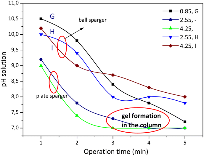 | ||
| Fig. 5 The pH profile at different operation times from sodium silicate concentration using a plate sparger and using a ball sparger. | ||
Experiment H was stopped at the fourth minute and experiment I was stopped at the 3rd minute because a gel formed on the column. Experiments A to I were carried out using a plate sparger, but for experiments H and I the replacement was carried out using a ball sparger. Fig. 5 shows the profile of solution pH with operating time for experiments H and I using a plate sparger and ball sparger. The phenomenon of bubble formation using a ball sparger is slightly different. At the beginning of the CO2 absorption process for the H experiment (pH 12 to pH 10), some of the bubbles took the form of small spheres with tails until the first minute. In the following minutes the bubbles began to form rods that were spaced apart. The pH decreases until it reaches the final pH at a value of around 8 where the bubbles are rod-shaped and close together. The bubbles flow upward until they reach the surface of the liquid, relatively unchanged in shape and size. In accordance with Kalbfleisch et al. (2017), the higher gas velocities cause elongation of the bubbles due to liquid inertia.4 Experiment I with a ball sparger shows a phenomenon similar to experiment H. Fig. 6 shows the distribution of bubble sizes in experiments H and I. Measurements are in the direction of the length of the bubble rod, not the width of the bubble rod. The average bubble rod length for experiment H at pH 10 was 0.1 cm, while at the final pH 8 the bubble rod length was 0.8 cm. Meanwhile, the average bubble rod length for experiment I at pH 10.5 was 0.7 cm and at the final pH 8 the average bubble rod length was 1.4 cm. Up to five minutes of operation time, no gel formation was found in the column.
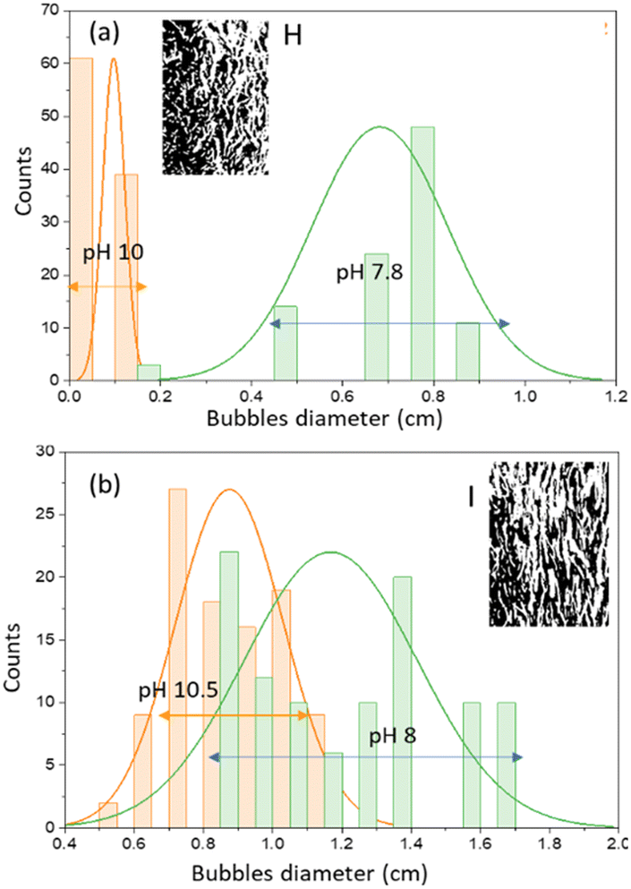 | ||
| Fig. 6 Bubble size distributions during initial saturation (pH 9–12) and at saturation (pH 7–8) using a sodium silicate concentration of 1% with a ball sparger in experiment H (a) and experiment I (b). | ||
Effect of pH and operation time on CO2 absorption
The sodium silicate aqueous solution as feed has a pH of 12. Studies on experiments A, B, and C show that the higher the superficial gas velocity, the lower the CO2 absorbed. It can be explained that the number of bubbles increases as the gas rate increases so that it is difficult for the bulk liquids to reach neutral pH. Observations after the operation time of 5 min showed that the bulk liquid as a 0.2% v sodium silicate solution had a pH of 9 (experiment C) which was inadequate to absorb CO2. Supposedly, at high pH the absorption of CO2 can take place. Meanwhile, in experiment A, the bulk liquid which had a pH of 8 was still able to absorb a small amount of CO2. Chen & Zhuo (2020) reported that the increase in pH improves the CO2 removal efficiency, and the overall mass-transfer coefficient increased with increasing the value of pH.9 In previous studies, it was also found that the pH of sodium silicate aqueous solution decreased as the absorbed CO2 increased.21,22 It can be stated that the CO2 absorption experiment with codes A, B, and C for 5 min performed with 2% v sodium silicate aqueous solution was less than optimal. Even though the small bubbles are evenly distributed, the CO2 barely reacts with the sodium silicate solution; as a result, there is still a lot of gas that escapes from the surface of the liquid. To achieve pH 7 and reduce gas holdup, increasing the operating time or increasing the liquid height in the column can be done.From the observation of the experiments D, E and F, with 6% v aqueous sodium silicate solution, CO2 absorbed for 5 min operation time was greater than in the previous experiments (A, B and C), except at low superficial gas velocities (experiment D). The operation time was quite precise because it reached pH 7 within 5 min and no gel formation was found. This can be considered to reduce high gas holdup by reducing operation time and increasing the liquid level in the column.
Observations on the CO2 absorption using 1% v sodium silicate solution in experiments G, H and I showed the high CO2 absorption based on the percentage of trona phase. However, the gas holdup is quite high and there is a tendency towards gel formation in the column. In experiment code I, the superficial gas velocity of 4.25 cm s−1 using a plate sparger must be stopped before the 5 min operation time is finished. The bubbles which were initially almost the same in size become larger due to the effect of the bubble coalescence. Apart from that, soft gel is also found on the column walls, especially on the top wall near the surface of the liquid. It can be explained that the rheological change where the liquid begins to polymerize at pH 7 causes an increase in the viscosity of the solution, as a result of which the bubbles that are restrained from flowing upward combine with other bubbles to become larger bubbles. CO2 absorption in this condition will decrease.
The CO2 absorption in the bubble column uses a ball sparger at the same superficial gas velocity (4.25 cm s−1) and the same aqueous sodium silicate concentration (1% v); the operation time can reach 5 min at a pH of around 8. That is why there is no gel formation in the column. However, the gas holdup is high. For the case of using a ball sparger where the particle product is dominated by the trona phase, further study is still needed. Our prediction is that silica is trapped in rod-shaped bubbles and carried by gas bubbles out of the column, so that the viscosity of the liquid decreases due to the reduction in silica.
Characteristic of precipitated particles at low concentrations of aqueous sodium silicate (0.2% v)
Experiments on bubble columns use a sodium silicate aqueous solution concentration of 0.2% v with a superficial gas velocity of 0.85 cm s−1 (code A). Observation of the bubbles created in the column shows that the micro-macro bubbles that are far from each other flow to the top of the liquid. In experiment A, the height of the liquid was unchanged relatively, and gas bubbles appeared on the surface of the liquid. CO2 absorption is relatively very low with gas holdup εg = 0.0393. Gas holdup calculations are based on the liquid height in the column. At low superficial gas velocity, the liquid level is almost unchanged, and small gas bubbles only appear on the surface of the liquid at a relatively low height. However, this shows that the gas is incompletely absorbed in the liquid. The phase of particle precipitated after gel drying was dominated by silica (SiO2) with a cubic crystal system of a (Å): 4.4300, b (Å): 4.4300 and c (Å): 4.4300. The capture of CO2 was indicated by the presence of sodium percentage as trona (C2H5Na3O8) phase in the precipitated silica sample from EDX analysis; the Na component was only 26.5%. Meanwhile, at the same concentration of sodium silicate solution, an increase in superficial gas velocity from 2.55 cm s−1 (code B) to 4.25 cm s−1 (code C) results in a decrease in Na component from 4.19% to 3.88%. This is consistent with the particle morphology observed from the SEM image. The number of bubbles increases slightly as the gas superficial velocity increases so that the gas holdup also increases to εg = 0.1874. The size of the spherical bubbles is almost uniform and evenly distributed over the column. Fig. 7 shows the diffraction patterns, phase matching and SEM image of precipitated particles for (a) experiment B and (b) experiment C. The XRD patterns for precipitated particles from experiments B and C are almost the same, where the carbonate salt peak was absent. It is likewise the XRD pattern for experiment A, where the carbonate salt peak appears less.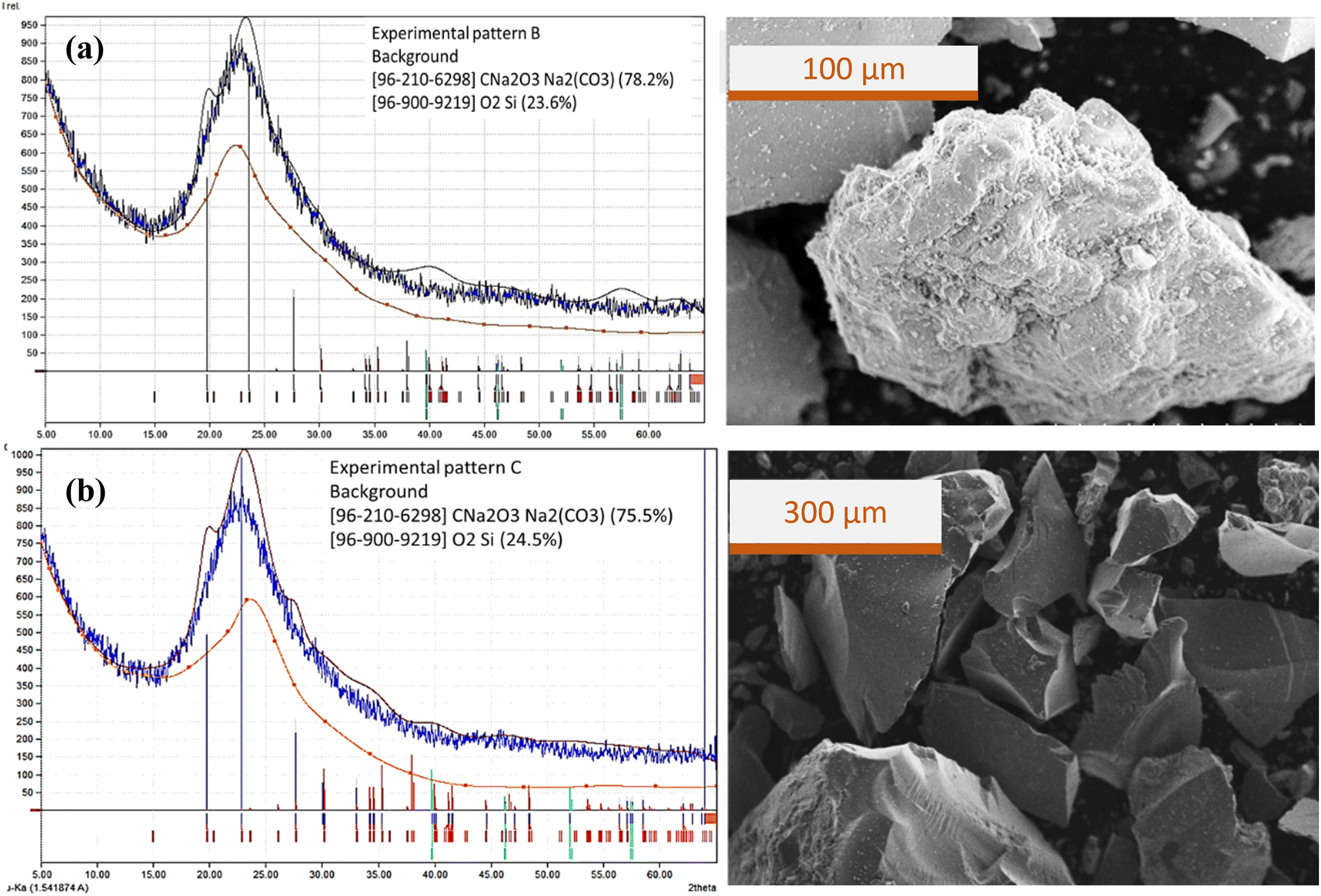 | ||
| Fig. 7 Diffraction patterns, phase matching and SEM image of precipitate particles from (a) experiment B and (b) experiment C. | ||
Silica-dominated precipitated particles are not uniform in shape and size; it appears that carbonate salts are trapped in the silica matrix. In the previous studies, low CO2 superficial velocity (0.3 cm s−1) produces precipitated spherical silica particles with an almost uniform size.18 From this comparison it is clear that the uniformity of the size and shape of the bubbles in the bubble column does not guarantee that the precipitated particles have a uniform size and shape. The formation of silica gel from bubble column operations is from a collection of larger molecules (colloidal gel) rather than from a network of individual molecular chains (polymer gel).13,14
Characteristic of precipitated particles at a concentration of aqueous sodium silicate of 0.6% v
Experiments on bubble columns use a sodium silicate solution concentration of 0.6% v with superficial gas velocities of 0.85 cm s−1 (code D), 2.55 cm s−1 (code E), and 4.25 cm s−1 (code F). The precipitated particles prepared from experiment E had almost the same phase as the precipitated particles prepared from experiment F (Fig. 8). The trona phase in particles prepared from experiment E reached 66%. Meanwhile, the trona phase prepared from experiment F was 59%; this is consistent with the SEM image (Fig. 4b).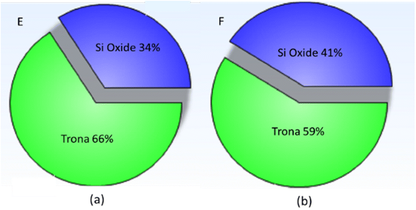 | ||
| Fig. 8 XRD phase precipitated particle prepared from (a) experiment E and (b) experiment F. | ||
The crystal system of trona (C2H5Na3O8) is monoclinic with a (Å): 20.4220, b (Å): 3.4910 and c (Å): 10.3330. Silicon dioxide (SiO2) is a cubic crystal. An increase in the superficial gas velocity shows a decrease in the trona phase from 66% to 59%. The decrease in the trona phase along with the increase in the superficial velocity of the gas may be due to the increase in bubble size. The large bubbles created at high aqueous solution concentrations cause the effective gas–liquid contact area to be restrained, so that the mass transfer rate is weakened.5
Fig. 9 shows the diffraction patterns, phase matching and SEM images of precipitated particles prepared by (a) experiment D and (b) experiment F. The XRD pattern for particles from experiment D shows fewer carbonate salt peaks than the XRD pattern for particles from experiment F. Observations on SEM images show differences in silica morphology where in experiment D the carbonate crystals are trapped in the silica matrix while in experiment F the carbonate crystals appear to fill the surface of the particle.
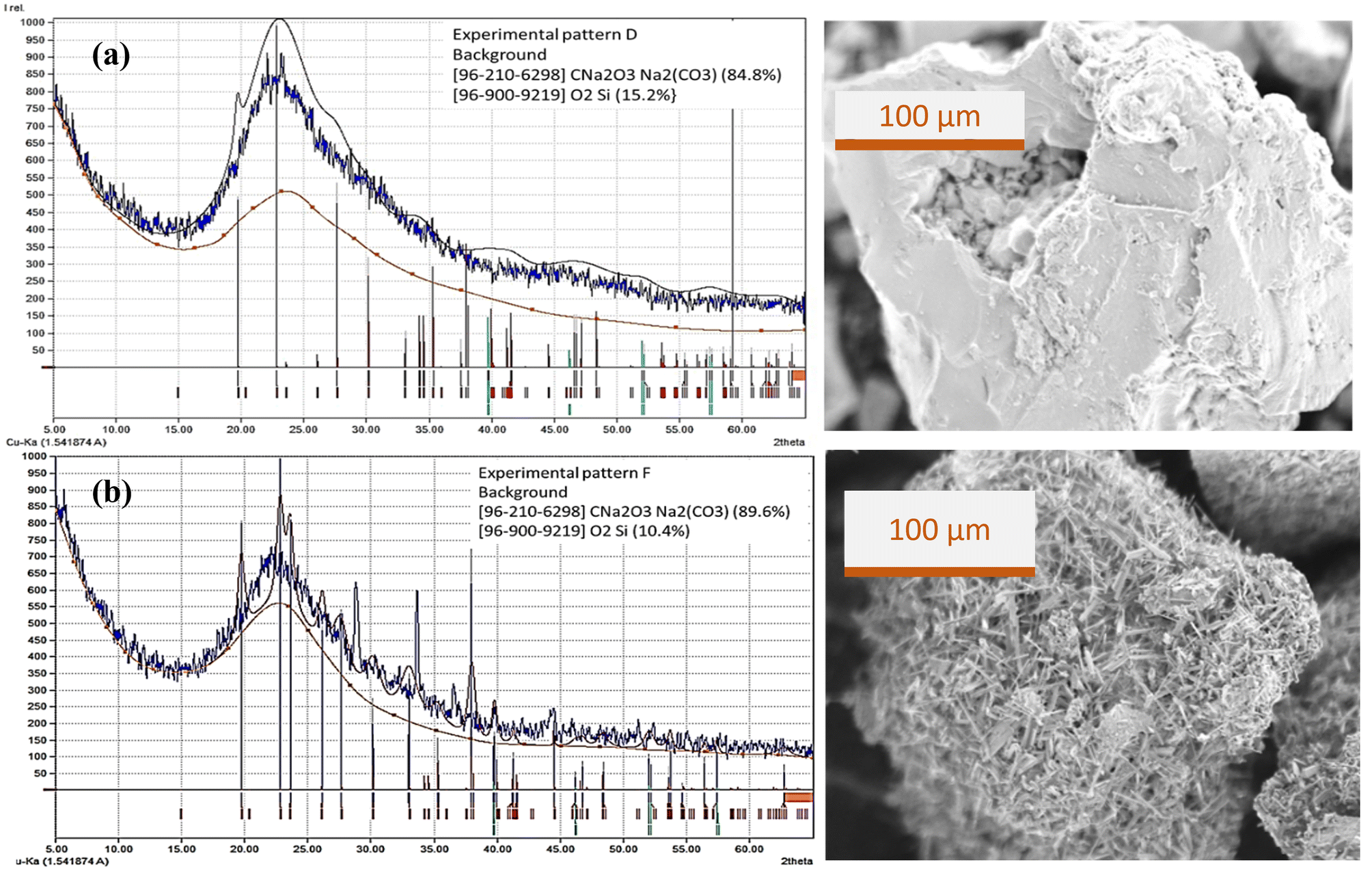 | ||
| Fig. 9 Diffraction patterns, phase matching and SEM image of precipitated particles from (a) experiment D and (b) experiment F. | ||
Characteristic of precipitated particles at a concentration of aqueous sodium silicate of 1% v
The experiments on the bubble columns used sodium silicate aqueous solution at a concentration of 1% v with superficial gas velocities of 0.85 cm s−1 (code G), 2.55 cm s−1 (code H), and 4.25 cm s−1 (code I). Gas holdup (εg) was in the range of 0.291–0.334. The percentage of trona phase (sodium carbonate hydrate, Na3H(CO3)2(H2O)2) in experiments G, H, and I was obtained, respectively, to be 52%, 50%, and 88% (Fig. 10). The hydrate content in sodium carbonate crystals may be related to incomplete drying of the gel. Natrite or sodium carbonate (Na2CO3) phase of 24% was found in experiment H (Fig. 10b); it can be stated that the precipitated particle phase was dominated by carbonate crystals (74%).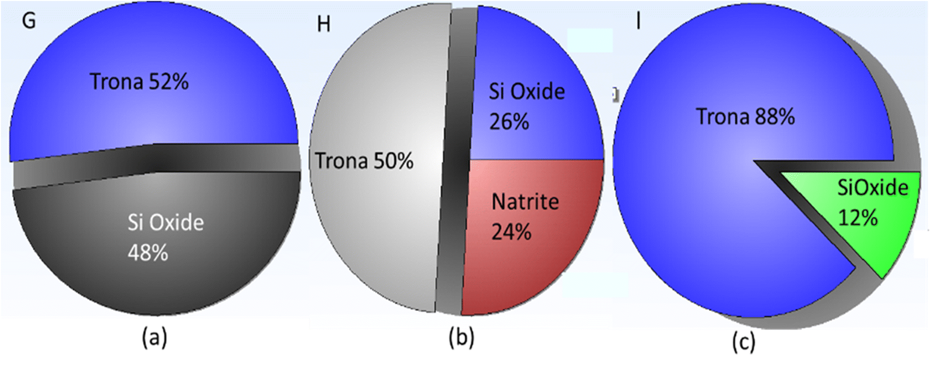 | ||
| Fig. 10 XRD phase precipitated particle prepared by experiments (a) G, (b) H, and (c) I. | ||
The morphology of the precipitated particles at high sodium silicate aqueous concentrations (experiment I) shows that carbonate salt crystals dominate in the surface of the particles (Fig. 11). This is consistent with the XRD pattern and XRD views regarding the percentage of trona crystal phase of 88% (Fig. 10c). The appearance of trona is white, needle-like. Sodium carbonate (Na2CO3) peaks can be observed at 32.4053°, 36.7897°, 37.9278°, 39.9552°, 41.3763°, 46.4313°, 48.243° and 52.5203° with monoclinic crystal types.
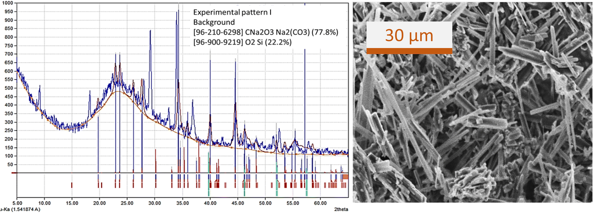 | ||
| Fig. 11 XRD pattern, matching phase, and SEM image of precipitated particles prepared by experiment I. | ||
The silica oxide (SiO2) phase in the particles prepared from experiment I-code was only 12%. This may occur because at high flow rates and high silicate concentrations where the stem bubbles flow quite rapidly they can carry silica (Si) trapped in gas bubbles. Meanwhile, sodium carbonate hydrate, which has a greater molecule size and weight, remains in the liquid in the column.
Crystallite size and weight of precipitated particles
The crystallite size of formed precipitated silica was determined using the Debye Scherrer equation, as shown in Fig. 12. The Debye Scherrer equation shows that the crystallite size value will be inversely proportional to the FWHM value, while the FWHM value is influenced by the intensity of each crystal plane, where the higher the intensity, the lower the FWHM value. The crystallite size based on the Debye Scherrer equation was obtained in the range of 9.1814–41.2978 nm. The silica crystallite sizes resulting from this calculation are in accordance with the silica size range reported by Sun et al., (2022) in the range of 2.03–55.95 nm using the Debye Scherrer equation.23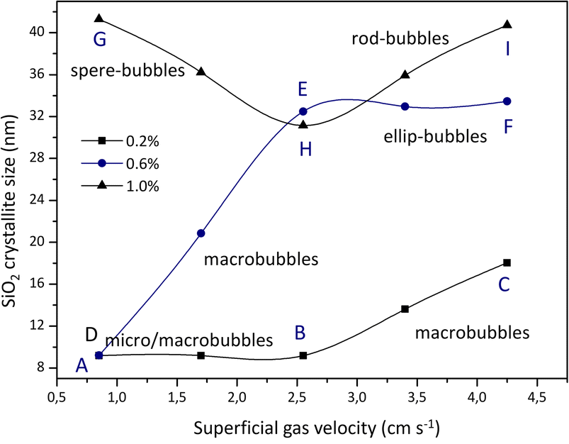 | ||
| Fig. 12 Crystallite size of SiO2 obtained from different sodium silicate concentrations and gas superficial velocities. | ||
The effect of superficial velocity on crystallite size appears to be more significant than on the weight of precipitated particles (Fig. 13). As previously described, the formation of silica gel is influenced by the final pH (at an operating time of 5 minutes) where the aging process will begin. In experiment A, microbubbles are close to macrobubbles where the size of the silica particles is in the range of 9 to 10 nm. The formation of silica particles during aging at pH 8 for 48 hours is dominated by silica where a small amount of sodium carbonate salt is trapped in it. As reported by Zhang et al., (2021) CO2 microbubbles accompanied by changes in temperature can produce spherical silica particles with a fairly high surface area.12 This is possible because the sodium carbonate salt is almost absent in the silica gel.
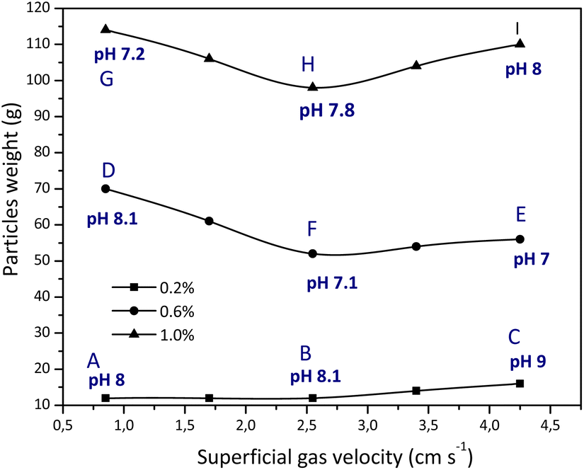 | ||
| Fig. 13 Particle weight of precipitated particles at different superficial gas velocities and pH. | ||
The crystallite size of precipitated silica increased with increasing superficial gas velocity, except when 1% v sodium silicate was used the particle size from experiment G decreased significantly. This is related to the growth of silica crystals in the condensation reaction, which is influenced by the presence or absence of sodium carbonate salt. Meanwhile, particle weight is more influenced by the concentration of the sodium silicate aqueous solution. Increasing the concentration of aqueous sodium silicate solution and superficial gas velocity causes an increase in the amount of sodium carbonate salt in the silica matrix. There is a tendency for particle weight to decrease with an increase in superficial gas velocity. This is possible because the proportion of sodium carbonate is increasing in the silica matrix. Particle weight is also influenced by preparation during aging and drying where the trona phase or natrite phase (sodium carbonate) is contained in the silica matrix. In experiment I (4.25 cm s−1, 1% v) there was an increase in particle weight after replacing the plate sparger with a ball sparger. Replacement is carried out considering that the use of a plate sparger at this rate grows the gel in the column before reaching the specified operation time (5 min). The bubbles that appear in the form of rods are able to increase the sodium carbonate in the silica matrix. In addition, after an operating time of 5 minutes, the final pH still reaches 8 so that gel formation in the paint column from particles deposited at different superficial gas velocities can still be resolved.
Experiments using 1% v sodium silicate and a superficial gas velocity of 4.25 cm s−1 revealed that gel formed on the column after 3 minutes. At neutral pH the solution will change according to the rheology of gel formation; in this condition, the shape of the gas bubbles was dense irregular spherical (Fig. 14).
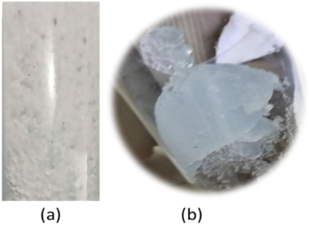 | ||
| Fig. 14 Visualization of (a) bubble gas in 1% v sodium silicate aqueous solution and (b) cap-shaped gel formation in the column. | ||
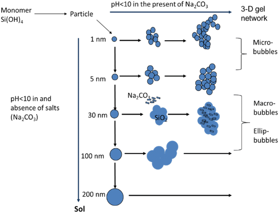
A single cap-shaped bubble appeared with the CO2 absorption at a sodium silicate aqueous solution concentration of 1.5% v, and superficial gas velocity of 2.55 cm s−1. The single bubble diameter is equivalent to the column diameter (5 cm). In this operation, a gel forms in the bubble column after 2.5 min. Fig. 15b shows a visualisation of cap-shaped or mushroom-like gel that forms in the column. The formation of a silica gel matrix through nucleation and condensation reactions is shown in Fig. 15.
 | ||
| Fig. 15 Silica gel matrix formation through nucleation and condensation reactions. | ||
The larger particle size indicates that the formation of the sodium carbonate silica matrix begins with the formation of single silica particles, which first enlarge and then coagulate due to the Ostwald ripening process. In the process of acidifying an aqueous solution of sodium silicate using hydrochloric acid carried out in a stirred tank at room temperature, it produces spherical silica even though there is sodium chloride salt trapped in it.14 There is consistency in the shape of the spherical silica particles even though there is a difference in the final pH from pH 9 to pH 7 and difference in concentration of silicate aqueous solution. In a stirred tank a homogeneous mixture is obtained, while in a bubble column a heterogeneous mixture of gas and liquid is obtained, which involves mass transfer. The nucleation of salt crystals grows together with the nucleation of silica when the size of the salt crystals is smaller than that of the silica particles. If the size of the salt crystals is larger than the size of the silica particles then growth occurs individually where the salt crystals will stick to the surface of the silica particles.24 Therefore, the shape and size of the silica should be undisturbed by the presence of salt crystals. However, from the results of previous research it was observed that spherical silica particles can form if there are no carbonate salts in the silica and bubble column operations with nano-microbubbles.12,14,21 In other words, the bubble column causes a change in the morphology of the precipitated silica unless nano or microbubbles are created in its operation. Observation of the SEM image (Fig. 8) for sodium carbonate or trona crystals shows that there are differences in morphology for experiments G, E and I, as shown in Fig. 16. It was observed that there was a slight transformation in the shape and size of the crystals from solid rod shapes to needle shapes. Solid rod-shaped sodium carbonate crystals are also found in operations with packed bed columns.21 The particle size distribution of sodium carbonate from experiments G, E and I is depicted in Fig. 16. The needle shape of sodium carbonate in experiment I was clearly observed with a length of 10–40 μm. This particle is four times longer compared with sodium carbonate produced from experiments G and E, which concludes that sodium silicate concentration and superficial gas velocity affect the morphology of the precipitated particles. In experiment G, the carbonate crystals were 4–12 μm in size and dominant at around 8 μm, and the size of the particles was 646![[thin space (1/6-em)]](https://www.rsc.org/images/entities/char_2009.gif) 155 μm. In experiment E, the size of the sodium carbonate crystals was mostly in the range of 7–8 μm, while the size of the particles varied from 134 μm to 411842 μm. In experiment I, the carbonate crystal size was dominant at 10 μm to 20 μm, while the particle size was an average of 132565 μm. In experiment F, the particles had a diameter of 93719–199,208 μm (mean: 132689 μm), while carbonate crystals were dominant at a size of 14–16 μm. It can be stated that the lower the salt crystal content, the larger the particle diameter. This is according to the illustration in Fig. 15. The shapes of the bubble distribution in experiments G, E/F and I are spherical, ellipsoidal, and rod-bubbles, respectively. The sizes of particles in experiments A, B, and C were, respectively, in the range of 114986–485442 μm, 165579–242391 μm, and 162820–544217 μm. Meanwhile, experiment D has an average size of 261284 μm. The largest particle size was obtained in experiment C. Even though the particle sizes from experiments A, B and C are larger than the particle sizes from experiments E, F and I, the weight of the particles from experiments A, B and C is lower than the weight of the particles from experiments E, F and I.
155 μm. In experiment E, the size of the sodium carbonate crystals was mostly in the range of 7–8 μm, while the size of the particles varied from 134 μm to 411842 μm. In experiment I, the carbonate crystal size was dominant at 10 μm to 20 μm, while the particle size was an average of 132565 μm. In experiment F, the particles had a diameter of 93719–199,208 μm (mean: 132689 μm), while carbonate crystals were dominant at a size of 14–16 μm. It can be stated that the lower the salt crystal content, the larger the particle diameter. This is according to the illustration in Fig. 15. The shapes of the bubble distribution in experiments G, E/F and I are spherical, ellipsoidal, and rod-bubbles, respectively. The sizes of particles in experiments A, B, and C were, respectively, in the range of 114986–485442 μm, 165579–242391 μm, and 162820–544217 μm. Meanwhile, experiment D has an average size of 261284 μm. The largest particle size was obtained in experiment C. Even though the particle sizes from experiments A, B and C are larger than the particle sizes from experiments E, F and I, the weight of the particles from experiments A, B and C is lower than the weight of the particles from experiments E, F and I.
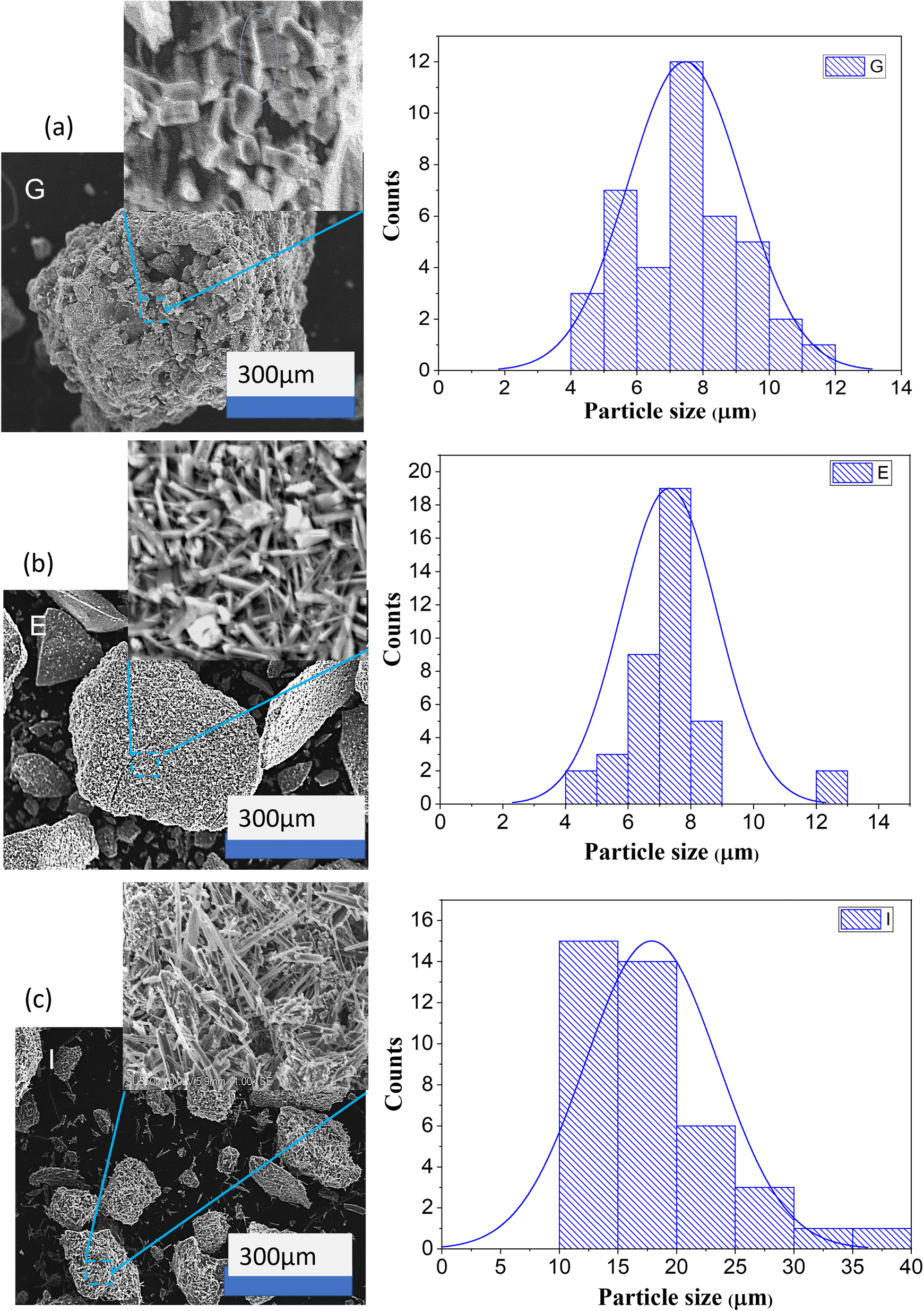 | ||
| Fig. 16 Morphology and particle size distribution of precipitated particles in experiment G (a), E (b) and I (c). | ||
The difference in the calculation results using the Scherrer equation and the measurement results using SEM is caused by the layer morphology. The crystal morphology produced by scanning the secondary electron beam in the SEM allows for sufficient image magnification to be measured directly.
Effect of the sparger on bubble shape and CO2 absorption
Two types of micropore stone spargers, namely, a plate sparger and ball sparger, were used in this study to observe the shape and distribution of bubbles in the bubble column. Experiments with A-code to I-code use a plate sparger, where on average the bubbles are spherical in shape, except at high superficial velocities and high aqueous sodium silicate concentrations the bubbles are ellipsoidal in shape, as discussed in the previous section. The regime in which separate bubbles are generated from the sparger and dispersed uniformly without coalescence is defined as the homogeneous regime (low glass flow rate regime). A homogeneous regime will result in an almost linear increase in gas holdup with increasing gas velocity.3 The regime of bubble formation was determined by the Reynolds number based on calculating the average value of the gas velocity through each hole.3The bubble formation using plate and ball spargers is shown in Fig. 17. The ball sparger was applied in a bubble column operating at superficial gas velocities of 0.85 cm s−1, 2.55 cm s−1 and 4.25 cm s−1 and 1% v sodium silicate solution in water. The ball sparger produced irregularly shaped bubbles at low superficial gas velocity, and there was no uniformity in the distribution of radial bubbles near the sparger region. The rod-shaped bubbles are distributed almost evenly in the liquid at high superficial gas velocity (4.25 cm s−1).
 | ||
| Fig. 17 Bubble shape from (a) a micropore plate sparger and (b) micropore ball sparger. | ||
Rod-shaped bubbles are not a natural occurrence like spherical bubbles. Bubbles tend to have a spherical shape due to the surface tension of the liquid within them, which minimizes their surface area. We compare the absorption results from columns with plate spargers and spherical spargers for flow rates of 2.55 cm s−1 and 4.25 cm s−1. In experiments E and F using plate spargers, the trona phase decreased from 66% to 59% at pH 7 and pH 7.3, respectively. In experiment H and experiment I (ball sparger) there was an increase in the trona phase from 74% to 88% even though the pH value increased from 7.3 to 8.
Rod-shaped bubbles have a larger surface area than spherical bubbles if the volume of both bubbles is the same. Our opinion is that rod-shaped bubbles from ball spargers can be created in high concentration of aqueous solution, non-Newtonian fluids, and provide a large mass transfer surface area. The void volume in the column with the rod-shaped bubbles is predicted to be larger than that with spherical bubbles, so the gas–liquid contact area of the rod-shaped bubbles is larger at the same superficial gas velocity and high aqueous solution concentrations. Further research is needed regarding mass transfer from single rod-shaped gas bubbles into aqueous sodium silicate solutions.
Both types of spargers provide the same high gas holdup (0.393–0.433) but in operation using a ball sparger there is no gel formation within an operation time of 5 min under the condition of pH 8. Meanwhile on the plate sparger, a gel is formed before the operation time reaches 5 min. It can be considered to reduce gas holdup for absorption operations using a ball sparger by increasing the liquid height in the column.
Conclusions
The superficial gas velocity in the bubble column and the concentration of sodium silicate aqueous solution facilitate the formation of spherical-bubbles, ellipsoidal-bubbles, and rod-shaped bubbles. The plate sparger creates spherical bubbles and ellipsoidal bubbles depending on the concentration of sodium silicate aqueous solution and gas flow. Rod-shaped bubbles are created from the ball sparger primarily at relatively high concentrations of sodium silicate. The CO2 capture and the formation of precipitated particles (gel formation) is influenced by the pH of the solution, where the gas holdup plays an important role in the pH change. The precipitated particles are colloidal silica gel with carbonate salts (trona) attached to it. The trona phase (C2H5Na3O8) reached 88% in the preparation of 1% aqueous sodium silicate at a superficial gas velocity of 4.25 cm s−1 using the ball sparger. There is a correlation between the size and shape of the bubbles on the morphology of the precipitated particles. Based on experimental results, semi-batch operations can be scaled up to continuous operations where the liquid flows out after reaching a certain height and a certain flow rate by considering the liquid residence time. The absorption of CO2 in the bubble column in this experiment uses pure CO2, but for industrial applications it will be used to remove CO2 in the flue gas. The CO2 content in flue gas varies depending on the source; generally, flue gas contains around 7–25% CO2. Referring to the CO2 content, it is possible to obtain high CO2 recovery from flue gas using sodium silicate aqueous solution. The precipitated product of silica-sodium carbonate composite can be further used as catalysts. Optimization on bubble column performance and study of catalyst applications will be carried out in future studies.Author contributions
Srie Muljani: conceptualization, data curation, visualization, formal analysis, investigation, funding acquisition, writing- original draft; Heru Setyawan: data curation, supervision, writing – review & editing; Reva Edra Nugraha: formal analysis, validation, writing – review & editing.Conflicts of interest
There are no reported financial or personal conflicts of interest by the authors of this study.Acknowledgements
The authors would like to acknowledge the Universitas Pembangunan Nasional “Veteran” Jawa Timur for the financial support under Uber Publication research grant with contract number of SPP/166/UN.63.8/LT/V/2023.Notes and references
- S. Orvalho, M. C. Ruzicka, G. Olivieri and A. Marzocchella, Chem. Eng. Sci., 2015, 134, 205–216 CrossRef CAS.
- D. Gao, X. Li, B. Hou, F. Lu, M. Ye, A. Wang and X. Wang, Chem. Eng. Sci., 2022, 252, 117532 CrossRef CAS.
- M. Polli, M. Di Stanislao, R. Bagatin, E. A. Bakr and M. Masi, Chem. Eng. Sci., 2002, 57, 197–205 CrossRef CAS.
- A. Kalbfleisch and K. Siddiqui, Int. J. Multiphase Flow, 2017, 94, 1–16 CrossRef CAS.
- X. Dong, Z. Liu, F. Liu, Z. Li, W. Wei, X. Wang and X. Xu, Chem. Eng. Res. Des., 2019, 142, 25–33 CrossRef CAS.
- G. Besagni and F. Inzoli, Chem. Eng. Sci., 2017, 170, 270–296 CrossRef CAS.
- S. Shu, D. Vidal, F. Bertrand and J. Chaouki, Renewable Energy, 2019, 141, 613–631 CrossRef CAS.
- C. O. Vandu, B. van den Berg and R. Krishna, Chem. Eng. Technol., 2005, 28, 998–1002 CrossRef CAS.
- P. C. Chen and S. H. Zhuo, Crystals, 2020, 10, 1–14 Search PubMed.
- J. Cai, J. Huang, A. Cao, Y. Wei, H. Wang, X. Li, Z. Jiang, G. I. N. Waterhouse, S. Lu and S. Q. Zang, Appl. Catal., B, 2023, 328, 122473 CrossRef CAS.
- W. J. Nock, S. Heaven and C. J. Banks, Chem. Eng. Sci., 2016, 140, 171–178 CrossRef CAS.
- Y. Zhang, Z. Zhang, D. Feng, F. Zhang, J. Gao, M. Xie, Y. Zhao, S. Sun, G. Chang and Y. Qin, Carbon Capture Sci. Technol., 2021, 1, 100002 CrossRef CAS.
- E. Katoueizadeh, M. Rasouli and S. M. Zebarjad, Mater. Chem. Phys., 2021, 272, 124994 CrossRef CAS.
- S. Muljani, H. Setyawan, G. Wibawa and A. Altway, Adv. Powder Technol., 2014, 25, 1593–1599 CrossRef CAS.
- C. J. Brinker and G. W. Scherer, Sol-gel science: the physics and chemistry of sol-gel processing, Academic press, London, 2013 Search PubMed.
- K. K. T. Phan, T. Truong, Y. Wang and B. Bhandari, Food Eng. Rev., 2021, 13, 3–14 CrossRef CAS.
- D. Ohde, B. Thomas, S. Matthes, S. Tanaka, P. Bubenheim, K. Terasaka, M. Schlüter and A. Liese, RSC Adv., 2021, 11, 4087–4096 RSC.
- K. Eskandari, B. Karami and S. Khodabakhshi, Catal. Commun., 2014, 54, 124–130 CrossRef CAS.
- C. B. Cheah, L. E. Tan and M. Ramli, Composites, Part B, 2019, 160, 558–572 CrossRef CAS.
- S. J. Y. Lee, H. An, P. C. Wang, J. G. Hang and S. C. M. Yu, Int. Commun. Heat Mass Transfer, 2021, 120, 105000 CrossRef CAS.
- S. Muljani, H. Setyawan, F. I. Irianto and S. P. Fransisco, E3S Web Conf., 2021, 328, 01015 CrossRef CAS.
- R. Dewati, S. Suprihatin, K. Sumada and S. Muljani, Mater. Sci. Forum, 2019, 966, 14–18 Search PubMed.
- C. C. Sun, A. H. You and L. L. Teo, Int. J. Technol., 2022, 13, 1336–1343 CrossRef.
- G. Mahadevan, Q. Ruifan, Y. H. Hian Jane and S. Valiyaveettil, ACS Omega, 2021, 6, 20522–20529 CrossRef CAS PubMed.
| This journal is © The Royal Society of Chemistry 2023 |