DOI:
10.1039/D3RA04451C
(Paper)
RSC Adv., 2023,
13, 29735-29748
Synthesis of fungal chitosan–polystyrene modified by nanoparticles of binary metals for the removal of heavy metals from waste aqueous media
Received
4th July 2023
, Accepted 27th September 2023
First published on 10th October 2023
Abstract
The objective of this study was to assess the efficacy of fungal chitosan–polystyrene-Co-nanocomposites (FCPNC) as a material for the adsorptive removal of cadmium (Cd) ions from aqueous solutions. The synthesis and characterization of FCPNC were accomplished using various analytical techniques, including Fourier transform infrared spectroscopy (FTIR), scanning electron microscopy (SEM), Brunauer–Emmett–Teller (BET) analysis, and dynamic light scattering (DLS). The effectiveness of this adsorbent in removing Cd(II) species from solution matrices was systematically investigated, resulting in the achievement of a maximum adsorption capacity of approximately 112.36 mg g−1. This high adsorption capacity was detected using the following operational parameters: solution pH equals 5.0, 60 min as a contact time between the adsorbent and Cd(II) solution, Cd initial concentration of 50 ppm, adsorbent dosage of 0.5 g L−1 and room temperature. The process of cadmium adsorption by FCPNC was found to follow the Langmuir isotherm model, suggesting that a chemical reaction occurs on the biosorbent surface. Kinetic studies have demonstrated that the cadmium removal process aligns well with the pseudo-second-order model. The thermodynamic analysis revealed the following values: ΔH° = 25.89 kJ mol−1, ΔG° = −21.58 kJ mol−1, and ΔS° = 159.30 J mol−1 K−1. These values indicate that the sorption process is endothermic, spontaneous, and feasible. These findings suggest the potential of FCPNC as an exceptionally effective biosorbent for the removal of water contaminants.
1. Introduction
Currently, the supply of clean and safe drinking water for human consumption and usage is becoming increasingly limited owing to the rising need for it and the depletion of water resources. Additionally, water is becoming contaminated with various substances, such as sediments, nutrients, pathogens, dissolved oxygen, heavy metal ions, suspended solids, and pesticides.1 The release of toxic and cancer-causing heavy metals from industrial sources into ecosystems is a global issue that has raised widespread concern.2 Of all the pollutants found globally, the contamination of heavy metals is of great importance. This is because heavy metals cannot be easily broken down, leading to their accumulation and increasing concentration throughout the food chain, which can cause harsh health issues as they flow into our lives.3 Heavy metals are elements that have high density, are toxic, and can cause mutagenic effects even at low concentrations.4,5 Cadmium (Cd), copper (Cu), and cobalt are poisonous heavy metals that are of significant ecological concern. They can be found in industrial wastewater spawned from activities, such as battery manufacturing, mining operations, petroleum refining, tanneries, electroplating, and pigment fabrication.6 Heavy metals have a strong aptitude to bind with protein molecules, which can affect DNA replication and cell division. In some cases, heavy metal toxicity can be lethal and interrupt the balance of the entire ecosystem.7 Concurrently, trace quantities of metals are essential micronutrients for many biological and metabolic processes within the permissible limits in drinking and potable water.8 This study spotlights Cd ions, which are a widespread toxic heavy metal pollutant absorbed by humans in significant amounts.9 Cd is a heavy metal that degrades awkwardly and exists in numerous forms in wastewater. It does not have any biological roles and is known to be a contaminant to aquatic organisms.10 The maximum acceptable limit of Cd in drinking water is 0.005 mg L−1, which is equivalent to 1–10 μg.11 The safe level of Cd in the air is set at 0.2 μg m−3. The average safe intake of Cd from food is estimated to be around 10–50 μg. Cd is rapidly absorbed by vegetables and animal-based foods and is disseminated mainly in the liver and kidneys. High concentrations of Cd are mostly accumulated in shellfish (>1 μg g−1) and in the liver and kidneys of poultry species.12 The toxic nature of heavy metals has led government authorities to impose strict regulations on industrial wastewater discharge, and their exclusion has been a primary concern of ecological researchers for decades. There are many treatment routes for removing toxic pollutants from water and usually involve precipitation,13 ion exchange,14 cementation,15 membrane separation technology,16 and adsorption.17–20 The adsorption process is considered the best method for removing toxic pollutants, especially for effluents with moderate to low concentrations. Among the available methods, the adsorption technique has proven to be multipurpose, cost-effective, eco-friendly, and greatly effective in removing toxic inorganic pollutants.21
In recent years, there has been a significant increase in the development of biobased adsorbents, especially those made from renewable and sustainable natural biopolymers. Polysaccharides, such as chitosan, modified chitosan, and its composites,22 are among the auspicious choices that have attracted significant attention because they are profusely available in nature, renewable, sustainable, and have low cost and better performance compared to other materials used in the management of contaminated water.23
Fungal chitosan represents a promising alternative to chitosan compared to traditional sources, such as crustacean shells, which result in large quantities of acid and alkali-rich waste waters. It maintains superior physico-chemical characteristics. It can be tailored with predefined properties for various specialty purposes, such as industrial biotechnological processes and safe disposal of waste water, resulting in higher fabrication costs.24
The chemical structure of chitosan is unique and provides many opportunities for its modification through physical or chemical methodologies to broaden its applications for the elimination of various contaminants from water. Chitosan has both cationic and anionic moieties that make it appropriate for the removal of pollutants present in the form of either anions or cations.25 Therefore, numerous explanations enable materials made with chitosan to stop or at least minimize the destruction of water and the biosphere.
However, chitosan has shortcomings, such as a small specific surface area, poor mechanical strength, no porosity, and few functional groups, which limit its widespread application in water treatment.26 To improve the mechanical properties, solubility, and adsorption effect of chitosan, researchers have created nanomaterials for the production of new sorbents: nano-sized adsorbents maintain extremely good performance because of their high specific surface area and the absence of conflict with intra-particle diffusion.27
In this study, we examined the effectiveness of Fungal Chitosan–Polystyrene-Co-Nanocomposites (FCPNC) in removing cadmium ions from wastewater. The structural and textural characteristics of the introduced bio-composite structure were determined using various analytical techniques. Operational parameters for the process of Cd adsorption are optimized, and the related kinetics and thermodynamics studies are investigated in this work. The novelty of this study is based on the incorporation of a polystyrene structure (as a shell) with molecules of chitosan (core) to enhance their capability as adsorbents in acidic media or low pH values. Specifically, high molecular weight polystyrene (acid resistant and water insoluble) was combined with chitosan to restrict its solubility in media of low pH; hence, it can act as an efficient adsorbent in such media. The novelty of this study also extends to the loading of polystyrene particles onto chitosan using a special technique of polymerization, resulting in a shell with high porosity. This, in turn, could significantly enhance the accessibility of heavy metal species to the function groups of chitosan, leading to increased adsorption efficiency for the composite introduced in this work. Additionally, the decoration of a polystyrene shell by nanoparticles of two metals hydroxide is considered part of the novelty of this study in terms of enhancing the tendency of the introduced composite toward cation removal owing to the presence of extra negative functional groups.
2. Experimental
2.1. Collection of sample
The raw material was obtained from the El Sella area, located in the Halaib region, which is approximately 20 km west of Abu Ramad City, Egypt. This raw material was crushed with a jaw crusher until the whole sample passed through a 150 μm sieve. Then, the sample was thoroughly mixed, dried in an electric oven at 110 °C for 24 hours, and then cooled and stored for further use at the Nuclear Materials Authority (NMA) of Egypt.
2.2. Isolation and extraction of fungal chitosan
Fungi were isolated from raw materials in the El-Sella area, subsequently subjected to purification, and identified through microscopic examination and PCR analysis. The resulting pure fungal culture was used for chitosan extraction.28 Fungal chitosan extraction involved deproteination with dilute sodium hydroxide, followed by centrifugation and chitosan extraction under reflux conditions with HCl. Crude chitosan was precipitated at pH 9.0, washed, air-dried, and then used for nanocomposite synthesis.28,29
2.3 . Chemicals
In all steps of this procedure, all chemicals were used as received. Styrene, aluminum nitrate Al(NO3)3 and anhydrous cobalt chloride (CoCl2) were bought from Al-Gomhoria Company for Pharmaceuticals and Chemical Industries (Egypt). CdSO4, obtained from Fluka Chemika (Switzerland), was utilized to prepare standard cadmium solutions of 1.0 g L−1. Fresh cadmium standard solutions at the appropriate concentration were synthesized from the stock solution using double-deionized water just before use. All reagents and solvents used in this study were of analytical reagent grade.
The applied waste raffinate solution was provided by the Nuclear Materials Authority. The chemical components of the waste solution were evaluated using ICP-AES (Optima 2100DV, PerkinElmer, USA) as follows: sulfuric acid molarity of 1.0 M, Ca(II), and Fe(III) concentrations of 1.84 and 0.63 g L−1, and cadmium concentration of 50 mg L−1.
2.4. Preparation of polystyrene
Polystyrene polymer was synthesized using the emulsion polymerization technique, as reported in ref. 30 and 31. The emulsion was made by mixing an oil phase (20 wt%) with an aqueous phase representing 80 wt%. Practically, 4.96 g of styrene (monomer) was mixed with 0.494 g sodium dodecyl sulfate (surfactant) at room temperature until a homogeneous mixture was obtained. This mixture was then added to 20 mL of pre-heated deionized water at 60 °C (placed in a reflux system) under vigorous stirring, producing an emulsion. Subsequently, 0.23 g of potassium persulfate (polymerization initiator) was added to the produced emulsion, and stirring was continued for 2 h at 60 °C. After completion of the reaction time, the emulsion was transferred into an electric oven at 60 °C for 12 h to finalize the polymerization stage.
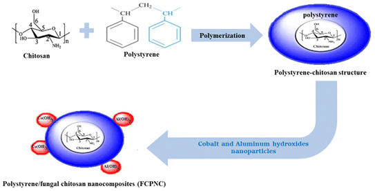
2.5. Synthesize of polystyrene/chitosan nanocomposites
In this stage, the same procedures of polystyrene preparation were followed, and an additional step was carried out. Specifically, an amount of chitosan (equivalent to 10 wt%) of the ultimate-designated composite was added to the aqueous phase. Experimentally, the chitosan particles were suspended in deionized water through the use of ultrasonic waves (at a power of 110 W) for 40 min.32 Immediately after the suspension was produced, a mixture of both the aqueous and oil phases was prepared, and the polymerization procedures were continued, as detailed in Subsection 2.5. After producing the polystyrene/chitosan, a further modification via the loading of the metal hydroxide nanoparticles was made. Particularly, 10 and 20 wt% of cobalt and aluminum hydroxide nanoparticles were added to the polystyrene–chitosan structure, respectively. The loading of these metal hydroxides was carried out using the co-chemical precipitation method, as reported in ref. 33 and 34. Practically, 0.1 M aqueous solution of CoCl2 and Al(NO3)3 was prepared by heating up to 70 °C under vigorous stirring. Then, the calculated amount (which represents 80 wt% of the designated composite) of polystyrene/chitosan structure was inserted into the prepared solution, and stirring was continued for approximately 10 min. Consequently, NaOH (0.1 M) was added dropwise under stirring until complete precipitation of cobalt and aluminum hydroxides (onto the polymer composite) was observed at a pH value of 10 ± 0.1. The resulting polystyrene/chitosan nanocomposites (FCPNC) were filtrated, washed several times with deionized water and dried at 60 °C in an oven for 3 hours, as shown in Scheme 1.
 |
| | Scheme 1 Schematic illustration of the synthesis of the FCPNC. | |
2.6. Characterization
FT-IR analyses for polystyrene and polystyrene/chitosan nanocomposites (FCPNC) were conducted using a PerkinElmer Spectrometer 400 (PerkinElmer Inc., Waltham, MA, USA) equipped with a Golden Gate diamond single-reflection device. The measurements were carried out in the region of 4000 ± 400 cm−1 at a resolution of 2 cm−1. SEM images for the composite were obtained by applying SEM, QUANTA FEG 250 (USA) equipped with an EDX analyzer. The specific area of the composite was measured by employing Quantachrome TouchWin™ version 1.21 instruments. The N2 adsorption measurements were performed at 77.35 K.
2.7. Adsorption studies
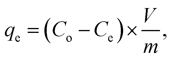
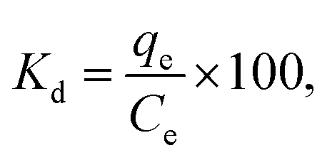
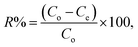
Systematic parametric studies were conducted to investigate the effects of various experimental parameters, including pH, contact time, adsorbent dose, initial cadmium ion concentration and temperature, on the adsorption of cadmium. The adsorption of cadmium onto FCPNC was conducted batch wise. For each experiment, 0.05 g of polystyrene was mixed with 100 mL of synthetic cadmium solution in a conical flask. The pH value of the solution was adjusted with 0.1 M HCl and NaOH solution. Phase separation was performed by centrifuging (Universal 320) at 2000 rpm. The sorbent was eradicated from the aqueous solution by filtration, and ICP-AES (Optima 2100DV, PerkinElmer, USA) was used to determine the residual concentration of cadmium ions in the aqueous solution (Ce, mg L−1). The quantity of cadmium adsorbed on the surface of polystyrene/chitosan nanocomposite (qe), removal efficiency of cadmium (%) and distribution coefficient (Kd) were calculated using eqn (1)–(3), respectively, as follows:35| |
 | (1) |
| |
 | (2) |
| |
 | (3) |
where Co (mg L−1) and Ce (mg L−1) are the liquid-phase concentrations of cadmium at initial and equilibrium, respectively; m (g) is the absorbent mass of FCPNC, V (L) is the suspension volume; and qe (mg g−1) is the amount of cadmium adsorbed on FCPNC.
3. Results and discussion
3.1. Extraction of fungal chitosan (AFC)
The growth of the individual pure fungal cultures in Potato Dextrose Broth (PDB) was observed for 7 days. The highest growth rate of mycelial dry weight was 17.8 g L−1. The best yield of fungal chitosan (mg per gram of dry mycelia biomass) was 134 mg g−1. Based on the biomass production, the highest recovery % of chitosan from fungi was 13.4%.
3.2. Characterization
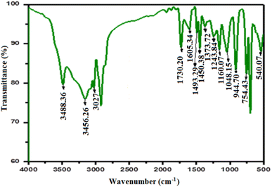
3.2.1. FTIR. In this study, the IR spectra of FCPNC and fungal chitosan\polystyrene (P-AFC) were analyzed and compared with the IR spectrum of extracted fungal chitosan (AFC). Several absorption bands in the FTIR spectrum were observed, as shown in Fig. 1a, and these bands were used to determine the basic structural features of fungal chitosan. In particular, an absorption band assigned to the O–H stretch was detected at 3438 cm−1, while another two bands belonging to the aliphatic C–H stretch were observed at 2920 and 2871 cm−1. Two absorption peaks seen at 1643 and 1541 cm−1 are assigned to NH2 deformation and N–H bending, respectively. Further peaks referring to the stretching bands of bridged –O– and C–O are noticed at wavenumbers of 1160 and 1085 cm−1, respectively. An absorption peak assigned to the stretching band of C–O in the primary hydroxyl group appeared at 1029 cm−1.36,37 After the modification of fungal chitosan through core–shelling by a layer of polystyrene, some additional peaks could be seen in the given FTIR spectrum, as depicted in Fig. 1b. Particularly, three absorption bands belonging to the mono-substituted benzene ring could be detected in between wavenumber values of 755 and 1048 cm−1. Moreover, two absorption bands attributed to both C![[double bond, length as m-dash]](https://www.rsc.org/images/entities/char_e001.gif) C and C–C aromatics were detected at 1424 and 1603 cm−1, respectively. The presence of C–H aromatics was confirmed by observing an absorption band at a wavenumber of 3025 cm−1.38 After the loading of cobalt and aluminum hydroxide nanoparticles, some additional peaks could be observed in the FTIR spectra (Fig. 1c and d). Particularly, two absorption bands at wave numbers of 880 and 1600 cm−1 were observed. These two peaks are assigned to both cobalt and aluminum hydroxides, respectively.34,39 Additionally, in this nanostructure, some variations in the intensities and broadness of the detected peaks were observed for both polystyrene and chitosan. These differences can be explained by the composition change40 as a result of loading the aluminum and cobalt hydroxide particles.
C and C–C aromatics were detected at 1424 and 1603 cm−1, respectively. The presence of C–H aromatics was confirmed by observing an absorption band at a wavenumber of 3025 cm−1.38 After the loading of cobalt and aluminum hydroxide nanoparticles, some additional peaks could be observed in the FTIR spectra (Fig. 1c and d). Particularly, two absorption bands at wave numbers of 880 and 1600 cm−1 were observed. These two peaks are assigned to both cobalt and aluminum hydroxides, respectively.34,39 Additionally, in this nanostructure, some variations in the intensities and broadness of the detected peaks were observed for both polystyrene and chitosan. These differences can be explained by the composition change40 as a result of loading the aluminum and cobalt hydroxide particles.
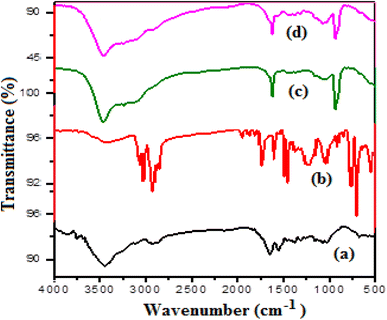 |
| | Fig. 1 FTIR for (a) fungal chitosan (AFC), (b) fungal chitosan + polystyrene (P-AFC), (c) fungal chitosan + polystyrene + 5% Co(OH)2 + 5% Al(OH)3 and (d) fungal chitosan + polystyrene + 10% Co(OH)2 + 10% Al(OH)3. | |
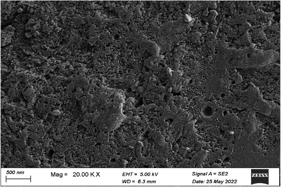
3.2.2. SEM analysis. The surface morphologies of blank polystyrene, polystyrene/fungal chitosan (P-AFC), and the ultimate nanocomposites (FCPNC) were studied using the given SEM images, as depicted in Fig. 2. For the polystyrene structure (Fig. 2A), a rough uniform surface was observed with the observation of large particles. However, some small particles were also seen dispersed within the large particles, which showed high domination, and onto their surface. Additionally, high porosity was observed in the displayed polymer, which can be referred to as its method of preparation, which is based on the usage of a high water concentration in an emulsion. A radical change was exhibited for the polystyrene/fungal chitosan composite, as illustrated in Fig. 2B. The demonstrated structure could show a smooth surface, to a high extent, with the observation of an increased porous nature. However, the detected pores in this structure were smaller in size than those observed in the case of pure polystyrene. Moreover, particles of different shapes and smaller sizes than those detected in polystyrene were observed for the composite structure. The observed changes between the two structures can be explained by the buildup of the polystyrene structure onto the core of the chitosan particles. Therefore, a nicer and greater homogeneity in the distribution of the polymer molecules in the case of the composite could be achieved compared to blank polystyrene. After the combination of cobalt and aluminum hydroxide with the latter composite (FCPNC), a strongly different morphology and surface features were observed, as demonstrated in Fig. 2C. A totally smooth and uniform surface was observed owing to the introduction of cobalt and aluminum hydroxide particles. A smooth skin-like layer can be detected for the investigated nanocomposites with no detection of obvious certain shapes for particles. Moreover, this nanocomposite revealed a quite porous nature; however, the pores were smaller than those of the other two structures. The observation of such morphology can be explained by the penetration and combination of the particles of cobalt and aluminum hydroxides into the pores of polystyrene and chitosan, creating a flat surface.
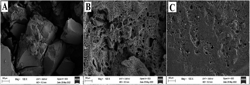 |
| | Fig. 2 SEM analysis for (A) blank polystyrene, (B) polystyrene/fungal chitosan composite (P-AFC) and (C) after the combination of cobalt and aluminum hydroxide with the latter composite (FCPNC). | |
3.2.3. BET analysis. The surface characteristics for polystyrene/fungal chitosan composite (P-AFC) and its sub-modified nanocomposites (FCPNC) were assessed through the Brunner–Emmett–Teller (BET). The isotherm patterns of the FCPNC are displayed in Fig. 3. Additionally, the full surface properties of both structures, including specific surface area, pore volume, and average pore radius, are depicted in Table 1. The isotherms of the two structures revealed two types of materials. Particularly, the polystyrene/fungal chitosan structure showed a material of type IV with a narrow mesoporous nature according to the IUPAC classification. However, its sub-driven nanocomposite exhibited a material of type III with a microporous texture.41,42 As illustrated in Table 1, the surface area of the polystyrene/fungal chitosan structure (47.08 m2 g−1) was slightly higher than that of the modified nanocomposite (FCPNC) structure, which showed a surface area value of 36.9 m2 g−1. Additionally, the latter structure presented a lower total pore volume and average pore radius than the polystyrene/fungal chitosan structure, which was numerically nearly half that of the polystyrene/fungal chitosan composite. The differences in surface properties of the two structures can be attributed to the incorporation of the metal hydroxide particles into the pores of polystyrene/fungal chitosan composite. Therefore, the nanocomposite (FCPNC) structure generally showed reduced surface characteristics compared to the (P-AFC) structure. The detected surface properties for the two structures agree well with the previously discussed SEM analysis.
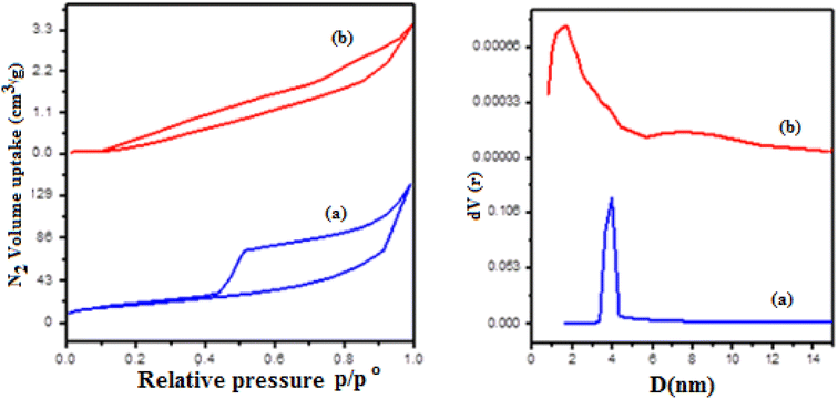 |
| | Fig. 3 The nitrogen sorption–desorption isotherms of (a) (P-AFC) composite and (b) polystyrene/fungal chitosan + Al/Co hydroxide nanocomposites (FCPNC). | |
Table 1 The nitrogen sorption–desorption isotherms of (P-AFC) composite and polystyrene/fungal chitosan + Al/Co hydroxide nanocomposites (FCPNC)
| Sample |
SBET (m2 g−1) |
Vp (cm g−1) |
pr (nm) |
| (P-AFC) composite |
47.08 |
0.217 |
3.92 |
| (FCPNC) nanocomposites |
36.9 |
0.093 |
1.79 |
3.2.4. DLS analysis. The sizes of the present particles on the prepared structures and their distribution, by percentages, are displayed in the provided DLS chart in Fig. 4. It can be observed that the blank polystyrene showed large particle sizes greater than 1 micron. Particularly, two peaks around 1 and 3 microns could be observed, as illustrated in Fig. 4A. However, the majority of the particles are centered at 1 micron. These large particle sizes can be referred to as the high molecular weight and chain length of the prepared polystyrene structure. After adding fungal chitosan to polystyrene, an obvious shift in the sizes of the composite particles was observed. Numerically, particles of sizes between 200 and 400 nm and around 1 micron (and less) were observed, as shown in Fig. 4B. However, the large particles are dominant in this structure, in which the major particle sizes are observed around 1 micron. The decrease in the overall size of particles in the second structure can be attributed to the presence of chitosan particles, which are smaller in size than polystyrene. A significant shift in size was observed in the composite (FCPNC), which contained both aluminum and cobalt hydroxide, as depicted in Fig. 4C. This radical reduction in the sizes of the composite particles can be referred to as the loading of the nanoparticles of the two metal hydroxides. The particles of sizes around 100 nm showed high domination in the presented polystyrene/fungal chitosan nanocomposites (FCPNC).
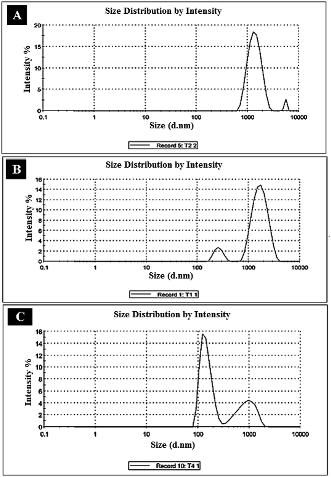 |
| | Fig. 4 Particle sizes/distribution of (A) polystyrene, (B) polystyrene/fungal chitosan (P-AFC), and (C) polystyrene/fungal chitosan nanocomposites (FCPNC). | |
3.3. Results of cadmium recovery by FCPNC
The optimization of the cadmium adsorption conditions was performed under various experimental conditions, such as initial pH, contact time, initial cadmium concentration, adsorbent dose, and temperature.
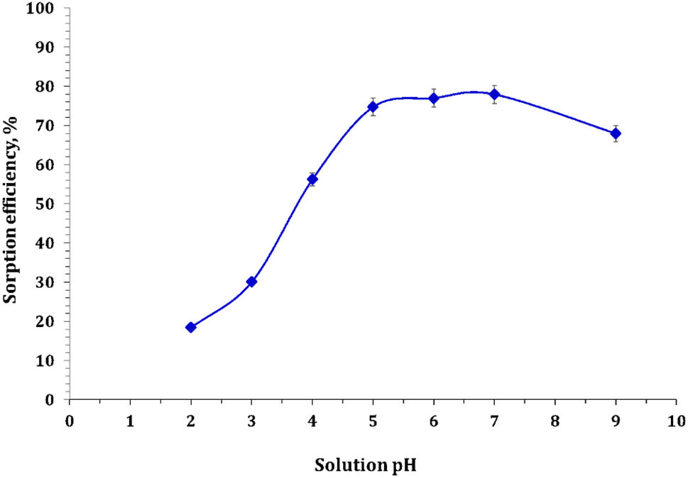
3.3.1. Effect of pH. In this study, the effect of hydrogen ion concentration was scrutinized by varying the solution pH from 2 to 9 while keeping all other parameters constant, including the adsorbent dose (0.5g L−1), contact time (12 h), initial metal ion concentration (50 ppm), and temperature (25 °C). pH is a crucial parameter for removing potentially toxic heavy metals because it affects the surface nature of the adsorbent and the degree of ionization of the metal to be detached. The effect of pH on the removal of Cd ions was evaluated using FCPNC, and the results are presented in Fig. 5. At a lower pH, less adsorption of Cd ions was noticed and credited to the competitive adsorption of H+ and metal ions on the surface of the composite. Protonation at a lower pH decreases the quantity of active binding sites for the adsorbed metal ion. As the pH increased, more adsorbent surfaces were exposed; hence, better adsorption was observed.43 More importantly, as the pH increases, functional groups, such as carboxylate and amino groups, are negatively charged in the case of chitosan, thus acting as scavengers for heavy metals on the composite carrying negative charges, which causes less revulsion of Cd(II) ions.44 The adsorption of Cd ion uptake increased as the pH increased to the maximum at pH 5.0. With a further increase in the pH of the solution, a greater possibility of precipitation of insoluble hydroxide complexes hinders the adsorption process.45 Therefore, the maximum removal efficiency was only 77.9% for the composite. In the literature, identical pH profiles have been reported for the retention of Cd(II) ions on a corn cob particle at pH 4.8–6.6 and 5.8–7.6.46,47
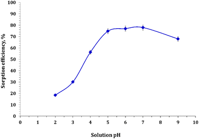 |
| | Fig. 5 Cadmium sorption as a function of solution pH. | |
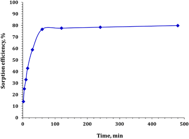
3.3.2. Effect of contact time. The effect of contact time on Cd ion uptake onto the composites was examined, as shown in Fig. 6. Batch adsorption experiments were conducted by altering the contact times while keeping other factors constant (pH 5.0, adsorbent dose 0.5 g L−1, initial metal ion concentration 50 ppm, and temperature 25 °C). The results indicate that Cd ion elimination increases with an increase in contact time, reaching a maximum of 480 min. Initially, a higher rate of adsorption was detected owing to the presence of a large number of vacant surface sites for Cd ion adsorption. However, after a certain amount of contact time, the remaining vacant surface sites become difficult to occupy because of the repulsive forces between the adsorbed solute molecules on the solid surface and the bulk phase. Therefore, an increase in contact time after the rapid enervation of adsorption sites did not significantly improve Cd ion uptake.46,48 Monitoring the contact time with the composites revealed that the sorption efficiency increased hastily, where over 76% of the Cd ion was adsorbed during the first 60 min and then became almost constant. Notably, accomplishing equilibrium time is crucial for cost-effective water treatment processes.
 |
| | Fig. 6 Variation of cadmium sorption as a function of contact time. | |
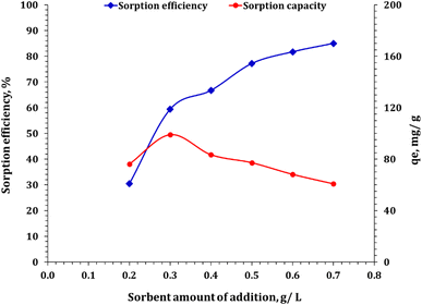
3.3.3. Effect of adsorbent dose. The study scrutinized the effect of adsorbent dosage on the removal of Cd(II) ions from an aqueous solution using FCPNC, as shown in Fig. 7. The pH (5.0), contact time (60 min), initial metal ion concentration (50 ppm), and temperature (25 °C) were kept constant, whereas a variable amount of FCPNC was used. The results obtained from several batch studies showed that the percentage of cadmium removal increases as the adsorbent dosage increases mainly owing to the increase in the surface area of the adsorbent. However, at a 0.5 g L−1 adsorbent dosage, the removal rate became nearly constant owing to resistance to the adsorbent surface. Therefore, for further work, the optimum adsorbent dosage was concluded to be 0.5 g L−1.
 |
| | Fig. 7 Sorbent dose effect on the cadmium ion sorption process. | |
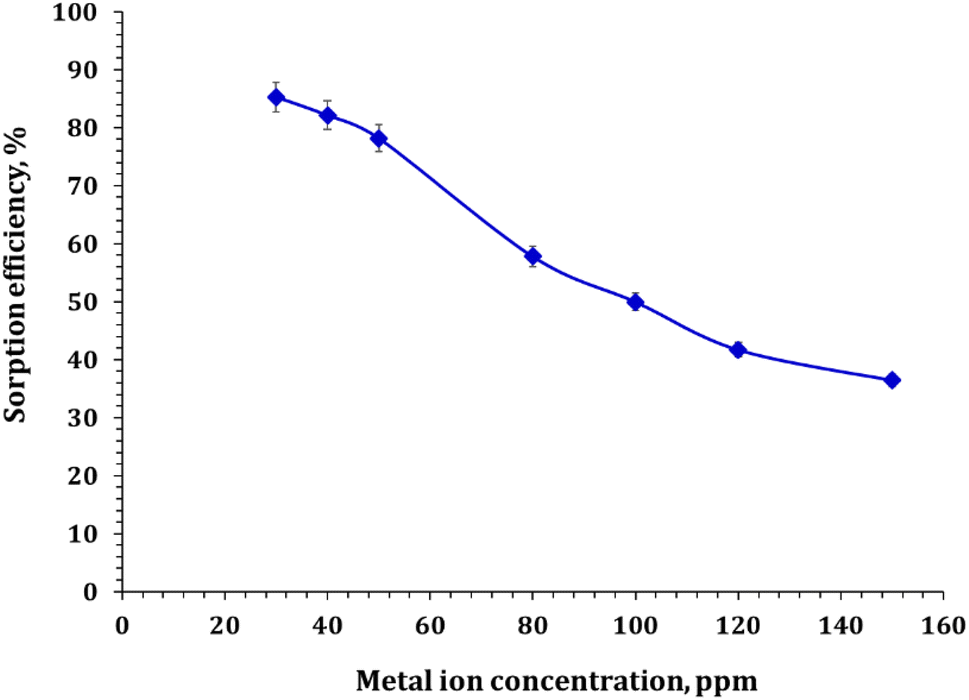
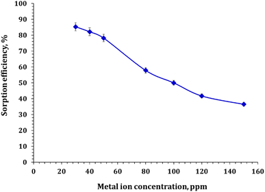
3.3.4. Effect of initial concentration. The effect of the initial concentration of cadmium on the adsorption rate was inspected by contacting a fixed mass (0.5 g) of FCPNC at room temperature and an initial pH of 5.0 with changeable initial cadmium concentrations (30, 40, 50, 80, 100, 120, and 150 mg L−1). The results, demonstrated in Fig. 8, showed that the percentage of cadmium adsorption decreased as the initial cadmium concentration increased. The adsorption efficiency decreased from 85.3% to 36.5% as the initial concentration of cadmium increased from 30 to 150 mg L−1. This can be attributed to the fact that at low concentrations, the ions are well adsorbed onto the adsorbent, resulting in a high removal rate. However, as the concentration of ions increases, the accessible active sites for adsorbing the ions become saturated, causing a decrease in the removal rate. Additionally, an increase in cadmium ions leads to an increase in the adsorption capacity per unit area, leading to an increase in the adsorbed quantity.
 |
| | Fig. 8 Cadmium sorption as a function of the initial concentration. | |
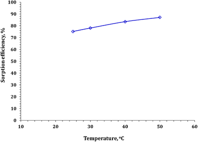
3.3.5. Temperature influence. Temperature plays a considerable role in adsorption processes, and its influence depends on the type of adsorption on the sorbent, whether exothermic or endothermic. In this study, the effect of reaction temperature on cadmium adsorption from aqueous solution using FCPNC was investigated, and the results are presented in Fig. 9. The experimental conditions included a shaking time of 60 minutes, a sorbent dose of 0.5 g L−1, a solution pH of 5.0, and an initial concentration range of 50 mg L−1. The data presented in the figure show that the sorption efficiency slightly improved with an increase in the reaction temperature. The results depicted in Fig. 9 confirm the endothermic nature of the dehydration process of Cd ions before their sorption on the solid surface, and it also reveals an increase in the mobility of Cd ions with temperature. Consequently, the optimal temperature for the remaining studies was chosen to be 25 °C.
 |
| | Fig. 9 Cadmium adsorption as a function of reaction temperature. | |
3.4. Adsorption kinetics
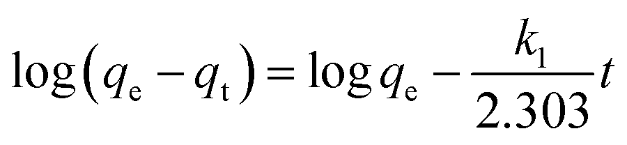
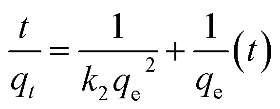
Most adsorption reactions are controlled by several successive steps, including (a) resistance to film diffusion, (b) resistance to intraparticle diffusion, and (c) the proper sorption reaction rate.49 Because the first step is excluded by sufficiently shaking the solution, the rate-determining step is one of the other two steps. To better understand the adsorption kinetics, numerous equations, such as pseudo-first-order (PFO), pseudo-second-order (PSO), and resistance to intraparticle diffusion (RID)50,51 were used for modeling the kinetic data. The linear forms of the PFO and PSO models can be clarified as eqn (4) and (5), respectively:| |
 | (4) |
| |
 | (5) |
where qe and qt (mg g−1) represent the amounts of Cd ions adsorbed at equilibrium and at time (t), respectively; and k1 (min−1) and k2 (g mg−1 min−1) are the rate constants of the PFO and PSO models, respectively. The values of model parameters (k1, k2, and qe) can be achieved from the linear plots of ln(qe − qt) versus t or t/qt versus t.
To evaluate the influence of intraparticle diffusion on the control of uptake kinetics, the data were treated using a simplified RID eqn (6):51
where
Kint is the intraparticle diffusion rate constant. The
Kint can be calculated from the slope of the regression line of
qt versus t1/2.
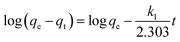
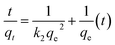
The values of the parameters of the various kinetic models are shown in Table 2. It can be observed that the correlation coefficients, R2, from the PSO model (the fitting results are shown in Fig. 11) were systematically higher than those from the PFO (Fig. 10) model. This was more likely to reflect that the rate-determining step might be chemical adsorption and that the adsorption behavior might involve valency forces by sharing electrons between the cadmium ions and adsorbent active sites.51 Cd ions may form a complex between the carboxymethyl and hydroxyl groups of the composite.
Table 2 Evaluated parameters of the kinetic models
| Lagergreen pseudo first-order |
k1 (min−1) |
0.017 |
| qecal (mg g−1) |
38.1 |
| qeexp (mg g−1) |
79.8 |
| R2 |
0.76 |
| Pseudo second-order |
k2 (min−1) |
0.001 |
| qecal (mg g−1) |
82.0 |
| qeexp (mg g−1) |
79.8 |
| h (mol g−1 h−1) |
7.80 |
| t1/2 (h) |
10.5 |
| R2 |
0.99 |
| Weber and Morris model (intraparticle diffusion) |
Stage I |
| ki (mg g−1 min−1/2) |
9.89 |
| C |
2.3 |
| R2 |
0.99 |
| Stage II |
| ki (mg g−1 min−1/2) |
0.22 |
| C |
75.0 |
| R2 |
0.99 |
 |
| | Fig. 10 Pseudo second-order kinetic model plot for cadmium adsorption using FCPNC. | |
 |
| | Fig. 11 Lagergreen kinetic model plot for cadmium adsorption using FCPNC. | |
The experimental results were inspected using Weber–Morris kinetic model (Fig. 12) to determine the sorption mechanism. The parameter values are illustrated in Table 2. The Weber–Morris plot exhibits two segments, indicating that Cd ion sorption using FCPNC is controlled with multiple mechanisms. The first mechanism could be a chemical reaction, i.e. surface complexation or chelation reaction, which refers to the stage of the sorption process up to equilibrium time (30 min). This stage is characterized by a rapid sorption reaction, which can be attributed to the accessibility of surface active sites on the modified chitosan.50,51 The second mechanism could be the physical reaction (intraparticle diffusion mechanism), which presents the stage of the sorption reaction after the equilibrium time. This stage is described by a slow reaction rate attributed to the occupation of most of the surface active sites, so the sorption process occurs inside the surface pores.52
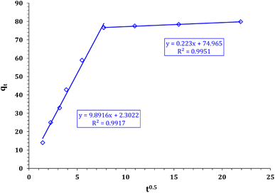 |
| | Fig. 12 Weber and Morris kinetic model plot for cadmium adsorption using FCPNC. | |
3.5. Adsorption isotherms
The adsorption isotherm characterizes the distribution of the solute between the liquid and solid phases at equilibrium at a constant temperature.
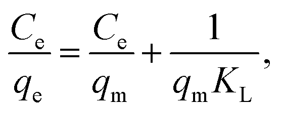
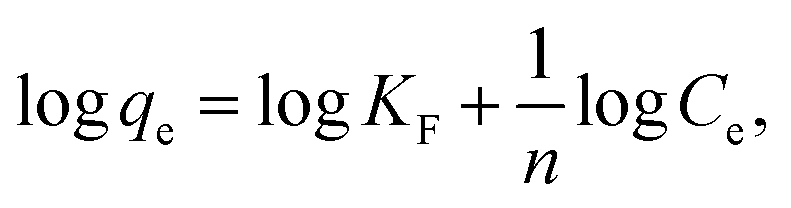
The equilibrium isotherm data were analyzed using the Langmuir and Freundlich models.49 The Langmuir model (eqn (7)) and the Freundlich model (eqn (8)) are as follows:53
| |
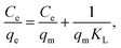 | (7) |
| |
 | (8) |
where
Ce (mg L
−1) and
qe (mg g
−1) are the equilibrium concentration and the equilibrium adsorption capacity, respectively;
qm (mg g
−1) is the maximum monolayer adsorption capacity.
KL (L mg
−1) is a constant related to the affinity of the binding sites;
KF (mg g
−1) and
n are Freundlich constants, indicating adsorption capacity and intensity, respectively. The values of the model parameters (
qm,
KL,
KF,
n) can be calculated from the slope and intercept of the linear plots of
Ce/
qe versus Ce or log
![[thin space (1/6-em)]](https://www.rsc.org/images/entities/char_2009.gif) qe versus
qe versus log
Ce, respectively.
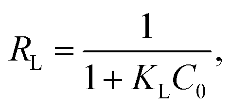
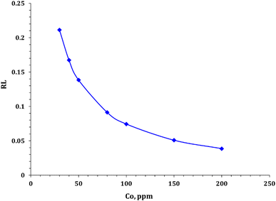
Furthermore, the Langmuir parameters can be used to predict the affinity between the sorbate and adsorbent utilizing the dimensionless separation factor RL:54
| |
 | (9) |
where
C0 is the initial concentration of cadmium ions. Values of 0 <
RL < 1 expose the nature of adsorption as favorable.
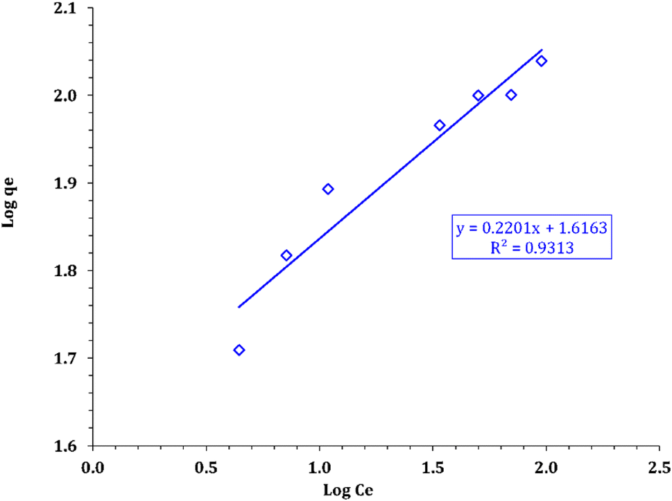
The parameters for these models and the coefficient values are shown in Table 3. The correlation coefficients demonstrated in Table 3 confirm the better fit of the experimental data by applying the Langmuir model (as shown in Fig. 13 compared with the Freundlich model in Fig. 14). This means that sorption can be described as a monolayer cover for the FCPNC sorbent. Furthermore, the sorbent possesses a homogeneous distribution of surface-active sites.53 The maximum adsorption capacity (qm) obtained using the Langmuir model at a constant temperature is 112.36 mg g−1, which is consistent with the experimental value.
Table 3 Evaluated variables of isotherm models
| Freundlich isotherm model |
n |
4.54 |
| Kf (mg g−1) |
41.33 |
| R2 |
0.93 |
| Langmuir isotherm model |
Qm (mg g−1) |
112.36 |
| b (L mg−1) |
0.171 |
| R2 |
0.99 |
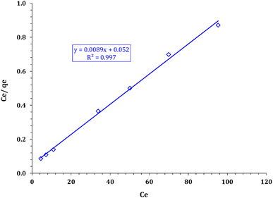 |
| | Fig. 13 Langmuir model plot for cadmium sorption using FCPNC. | |
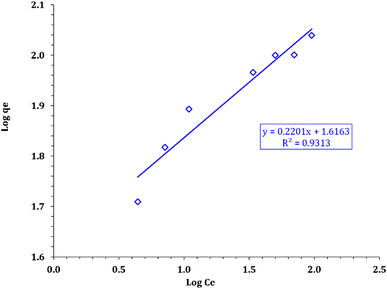 |
| | Fig. 14 Freundlich model plot for cadmium adsorption using FCPNC. | |
Additionally, as depicted in Fig. 15, all RL values for the adsorption of cadmium ions onto FCPNC range from 0 to 1, considering the initial concentration of cadmium (C0 = 10–100 mg L−1). This observation strongly indicates that the sorption process of Cd(II) on FCPNC is highly favorable. This further confirms that the adsorption of cadmium onto FCPNC is not only efficient but also preferred, regardless of the initial concentration of cadmium.
 |
| | Fig. 15 RL values for the sorption of cadmium onto FCPNC. | |
3.6. Comparison of the cadmium adsorption capacities of various adsorbents
The experimental maximum sorption capacity of (FCPNC) sorbent was compared with other accessible sorbents from the literature for cadmium extraction from aqueous solutions, as illustrated in Table 4. Although these data were obtained under different experimental conditions, they represent a useful criterion for comparing adsorption capacities. Table 4 shows that FCPNC has both competitive sorption capacities and quite fast sorption kinetics. The maximum adsorption capacity (qm) of (FCPNC) obtained by Langmuir isotherm for Cd(II) adsorption at 25 °C was 112.3 mg g−1. The high adsorption capacity of FCPNC toward cadmium ions reveals that the prepared composite could be promising for practical application in Cd ion removal from radioactive wastewater or mining.
Table 4 Reported adsorption capacities of Cd ions by different adsorbents
| Adsorbents |
Adsorbate |
Adsorption capacity, mg g−1 |
Ref. |
| MnO2-modified biochar (MBC) |
Cd(II) |
37.2 |
55 |
| ECH |
Cd(II) |
72.3 |
56 |
| Biochar modified with shrimp bran |
Cd(II) |
41.1 |
57 |
| CSAP |
Cd(II) |
84.0 |
58 |
| SMCS beads |
Cd(II) |
125.0 |
59 |
| Fe3O4 loaded |
Cd(II) |
97.8 |
60 |
| CTS/SA/Ca2+ |
Cd(II) |
110.7 |
61 |
| FCPNC |
Cd(II) |
112.3 |
PW |
3.7. Adsorption thermodynamics
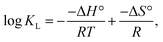
Thermodynamics, such as enthalpy (ΔH°, kJ mol−1), entropy (ΔS°, J (mol K)−1), and Gibbs free energy (ΔG°, kJ mol−1) of cadmium sorption, were determined by the correlation of the equilibrium constant according to the van't Hoff equation:54| |
 | (10) |
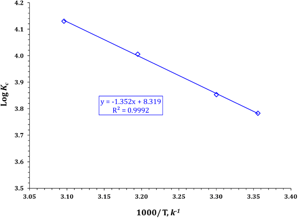
where R is the gas constant, T is the solution temperature (K), and KL is the Langmuir equilibrium constant (L mol−1). ΔH° and ΔS° were obtained from the slope and intercept of the linear van't Hoff plots of lnKL versus 1/T (Fig. 16) (R2 = 0.9992).
 |
| | Fig. 16 van't Hoff equation plot for cadmium sorption using FCPNC. | |
The van't Hoff plot, which shows the variation of logKc versus (1/T), is presented in Fig. 16, and the values of the thermodynamic parameters (i.e., ΔH°, ΔG°, and ΔS°) are listed in Table 5. The data suggest that the sorption process is endothermic, as indicated by the positive values of ΔH° (25.89 kJ mol−1).39,40 The negative values of Gibbs free energy (ΔG°) for all reaction temperatures suggest that the sorption process is spontaneous and feasible.53,54 Moreover, the decrease in ΔG° as temperature increases indicates that the sorption process is more favorable at high temperatures.62,63 The positive values of ΔS° for the uptake process indicate an increase in randomness at the solid–liquid interface.62,63 Similar thermodynamic behaviors (i.e., endothermic, spontaneous, and feasible sorption processes) were observed in the sorption of cadmium ions from aqueous solutions in previous studies.64,65
Table 5 Thermodynamic variables for cadmium sorption using the FCPNC
| ΔG (kJ mol−1) |
ΔH (kJ mol−1) |
ΔS (J mol−1 K−1) |
| 25 °C |
30 °C |
40 °C |
50 °C |
| −21.58 |
−22.35 |
−24.00 |
−25.54 |
25.89 |
159.30 |
3.8. Characterization of sorbent after cadmium adsorption
After capturing cadmium species using the prepared FCPNC, some differences could be observed in the FTIR of the spent adsorbent compared to the freshly prepared one, as presented in Fig. 17. In some details, three absorption bands could be observed at 600, 754, and 914 cm−1, referring to the complex formation between the cadmium species and the donating function groups in the chitosan structure.60 Additionally, some deformation in identifying the absorption band for the O–H group can be mentioned in the FTIR spectrum. Its broadness and intensity could be strongly affected and can be attributed to the complexation between water molecules and cadmium compounds, which are attached to the surface of the adsorbent.40 The stated variations in the FTIR spectrum of the spent adsorbent, compared to its corresponding fresh one, can confirm the successful removal of cadmium species by the introduced structure. The removal of cadmium species from the liquid waste media was further verified through SEM analysis, as shown in Fig. 18. The radical change in the morphology of the spent adsorbent, compared to the freshly made composite, could be observed in the given SEM image. Particularly, a skin layer with the detection of some large particles could be seen at the surface of the consumed adsorbent instead of the highly rough wavy surface, as observed in the fresh adsorbent. This skin layer can be recognized as the efficient adsorption of cadmium species by the adsorbent forming a mono-layer on its surface that strongly harmonizes with the Langmuir isotherm model.
 |
| | Fig. 17 FTIR spectra of FCPNC after cadmium adsorption. | |
 |
| | Fig. 18 SEM analysis of FCPNC after cadmium adsorption. | |
3.9. Cadmium elution and adsorbent reusability
To test the feasibility of FCPNC materials to be regenerated after the adsorption of cadmium ions, the desorption of Cd-loaded adsorbent was investigated using 1.0 M of different solutions, namely, sulfuric, nitric, and hydrochloric acids. The experimental conditions are as follows: 1.0 g L−1 sorbent dose, room temperature, and shaking time of 8 h. The obtained data in Table 6 show that the sulfuric acid solution exhibits the highest elution efficiency (95.3%). To assess the reusability of the adsorbent, the adsorption–desorption experiment was repeated in five cycles. The obtained results in Table 7 demonstrate that the sorption and the desorption percent slightly decreased from 93.0 to 88.5% for the sorption process and from 95.0 to 90.2% for the desorption process over the five cycles, reflecting the feasibility of sorbent recycling. This result shows that the adsorbent can be used efficiently in a real process, such as nuclear industry wastewater treatment.
Table 6 Cadmium recovery from loaded FCPNC using different eluting agents
| Eluting agent |
Sorption efficiency, % |
| 1.0 M hydrochloric acid |
87.1 |
| 1.0 M sulfuric acid |
95.3 |
| 1.0 M nitric |
71.7 |
Table 7 Adsorption and desorption cycles for cadmium recovery
| Recycling investigation |
| Cycle no. |
Sorption |
Desorption |
| 1 |
93.0 |
95.0 |
| 2 |
91.4 |
94.8 |
| 3 |
91.1 |
93.6 |
| 4 |
89.7 |
91.2 |
| 5 |
88.5 |
90.2 |
3.10. Cadmium ion elimination from waste solution (case study)
In accordance with the aforementioned data, the FCPNC was applied for Cd ion eradication from the liquid effluent. The application experiment was conducted based on the following parameters: 1.0 g L−1 sorbent dose, room temperature, and mixing time of 2 h. A buffer solution was used to adapt the initial pH of the raffinate solution. The exposed data demonstrate that the cadmium sorption capacity decreased from 112.36 mg g−1 (in the synthetic solution) to 96.74 mg g−1 (in the case study). The falling-off sorption capacity could be due to the competition between cadmium and different ions in the working waste solution (especially iron).
4. Conclusion
The FCPNC sorbent was synthesized, characterized, and found to be highly effective in recovering Cd ions from aqueous solutions. The maximum sorption capacity was observed at 25 °C and pH 5.0, with a value of 112.36 mg g−1. The FCPNC sorbent demonstrated meaningful improvements in adsorption capacity and selectivity for Cd ions, with fast adsorption kinetics and equilibrium reached within 60 minutes. The pseudo-second-order model was found to be appropriate in describing adsorption kinetics, indicating that the rate-limiting step may be chemical adsorption rather than mass transport. Isotherm and kinetic modeling confirmed that the sorption process followed both Langmuir and pseudo-second-order models. The interaction between the FCPNC sorbent and cadmium ions was found to be an endothermic, spontaneous, and feasible reaction.
Ethical approval
Ethical approval is not applicable to this study as it does not involve human or animal subjects. Therefore, no ethical committees, internal review boards, or specific guidelines were followed. Consent to participate and consent to publish are not applicable.
Data availability
Data will be made available on request.
Conflicts of interest
The authors declare that they have no competing interests, whether of a financial or personal nature.
References
- A. Vaseashta, in Advanced Sciences and Technologies for Security Applications, Springer, 2021, pp. 3–22 Search PubMed.
- I. Brčeski and A. Vaseashta, Adv. Sci. Technol. Secur. Appl., 2021, 333–370 Search PubMed.
- I. Karaouzas, N. Kapetanaki, A. Mentzafou, T. D. Kanellopoulos and N. Skoulikidis, Chemosphere, 2021, 263, 128192 CrossRef CAS PubMed.
- S. K. Behzad, M. M. Amini, A. Balati, M. Ghanbari and O. Sadeghi, J. Sol-Gel Sci. Technol., 2016, 78, 446–456 CrossRef.
- S. K. Behzad, A. Balati, M. M. Amini and M. Ghanbari, Microchim. Acta, 2014, 181, 1781–1788 CrossRef CAS.
- D. V. Antonov, R. S. Volkov, M. V. Piskunov and P. A. Strizhak, Tech. Phys. Lett., 2016, 42, 248–251 CrossRef CAS.
- P. T. Gauthier, W. P. Norwood, E. E. Prepas and G. G. Pyle, Aquat. Toxicol., 2014, 154, 253–269 CrossRef CAS PubMed.
- P. J. Thornalley, R. Babaei-Jadidi, H. Al Ali, N. Rabbani, A. Antonysunil, J. Larkin, A. Ahmed, G. Rayman and C. W. Bodmer, Diabetologia, 2007, 50, 2164–2170 CrossRef CAS PubMed.
- A. Shakya and T. Agarwal, Biochar Applications in Agriculture and Environment Management, 2020, pp. 77–98 Search PubMed.
- W. X. Wang and R. C. H. Dei, Environ. Pollut., 2001, 111, 233–240 CrossRef CAS PubMed.
- L. Järup, Br. Med. Bull., 2003, 68, 167–182 CrossRef PubMed.
- H. Kawashima, H. Nomiyama and K. Nomiyama, Environ. Res., 1988, 46, 48–58 CrossRef CAS PubMed.
- S. Rasalingam, R. Peng and R. T. Koodali, J. Nanomater., 2014, 2014, 617405 Search PubMed.
- D. Saravanan, T. Gomathi and P. N. Sudha, Int. J. Biol. Macromol., 2013, 53, 67–71 CrossRef CAS PubMed.
- A. Doridot, L. Robbiola and F. Téreygeol, ArcheoSciences - Revue d’archéométrie, 2006, pp. 15–24, https://journals.openedition.org/archeosciences Search PubMed.
- K. C. Khulbe and T. Matsuura, Appl. Water Sci., 2018, 8, 1–30 CrossRef CAS.
- A. M. Masoud, M. Saeed, M. H. Taha and M. M. El-Maadawy, Egypt. J. Chem., 2020, 63, 721–741 Search PubMed.
- M. M. El-Maadawy, Radiochem., 2019, 61, 331–338 CrossRef CAS.
- A. E. M. Hussein, W. M. Youssef, M. H. Taha and M. M. El-Maadawy, Uranium Adsorption from Aqueous Nitric Acid Solution by Solvent Impregnated Polypropylene, 2017, vol. 50 Search PubMed.
- M. M. Ali, A. A. Attia, M. H. Taha, M. M. El-Maadawy, A. M. Abo-Raia and A. Abouria, SPE Middle East Oil and Gas Show and Conference, 2019 Search PubMed.
- B. Volesky and Z. R. Holan, Biotechnol. Prog., 1995, 11, 235–250 CrossRef CAS PubMed.
- I. Muñoz, C. Rodríguez, D. Gillet and B. M. Moerschbacher, Int. J. Life Cycle Assess., 2018, 23, 1151–1160 CrossRef.
- J. Zhang, W. Xia, P. Liu, Q. Cheng, T. Tahirou, W. Gu and B. Li, Mar. Drugs, 2010, 8, 1962–1987 CrossRef CAS PubMed.
- O. M. Darwesh, Y. Y. Sultan, M. M. Seif and D. A. Marrez, Toxicol. Rep., 2018, 5, 348–356 CrossRef CAS PubMed.
- G. Crini and P. M. Badot, Prog. Polym. Sci., 2008, 33, 399–447 CrossRef CAS.
- M. G. Mahfouz, A. A. Galhoum, N. A. Gomaa, S. S. Abdel-Rehem, A. A. Atia, T. Vincent and E. Guibal, Chem. Eng. J., 2015, 262, 198–209 CrossRef CAS.
- Z. Wang, Y. Wang and C. Yao, J. Radioanal. Nucl. Chem., 2021, 330, 1263–1269 CrossRef CAS.
- B. Krishnaveni and R. Ragunathan, J. Pharm. Sci. Res., 2015, 7, 197–205 CAS.
- S. M. El-Sabbagh, S. S. Hussien, H. I. Mira, O. A. Desouky and D. M. Elgohary, Egypt. J. Exp. Biol., 2023, 19, 101 CrossRef.
- X. Xiao, F. Zhang, Z. Feng, S. Deng and Y. Wang, Phys. E, 2015, 65, 4–12 CrossRef CAS.
- G. Michailidou, I. Koumentakou, E. V. Liakos, M. Lazaridou, D. A. Lambropoulou, D. N. Bikiaris and G. Z. Kyzas, Polymers, 2021, 13, 3137 CrossRef CAS PubMed.
- M. S. A. Darwish, A. M. A. El Naggar, A. S. Morshedy and N. Haneklaus, Environ. Sci. Pollut. Res., 2021, 28, 3566–3578 CrossRef CAS PubMed.
- R. A. El-Salamony, S. A. El-Temtamy, A. M. A. El Naggar, S. A. Ghoneim, D. R. Abd El-Hafiz, M. A. Ebiad, T. Gendy and A. M. Al-Sabagh, Int. J. Energy Res., 2021, 45, 3899–3912 CrossRef CAS.
- A. Bakry, M. Adel, A. M. A. El Naggar and M. H. Helal, Egypt. J. Chem., 2022, 65, 605–615 Search PubMed.
- A. M. Masoud, Int. J. Environ. Anal. Chem., 2020, 102, 3124–3146 CrossRef.
- M. Zheng, B. Han, Y. Yang and W. Liu, Carbohydr. Polym., 2011, 86, 231–238 CrossRef CAS.
- A. S. A. Bakr, H. I. Al-Shafey, E. I. Arafa and A. M. A. El Naggar, J. Chem. Eng. Data, 2020, 65, 4079–4091 CrossRef CAS.
- A. M. A. El Naggar, M. S. Mostafa and M. T. Zaky, Fuel, 2016, 180, 218–227 CrossRef CAS.
- M. El Saied, A. M. A. El Naggar, F. I. Elhosiny and F. Y. El kady, J. Cleaner Prod., 2019, 218, 157–166 CrossRef CAS.
- X. Wang, R. Tang, Y. Zhang, Z. Yu and C. Qi, Polymers, 2016, 8, 338 CrossRef PubMed.
- R. S. Mohamed, A. A. Al Kahlawy, A. M. A. El Naggar and H. M. Gobara, New J. Chem., 2020, 44, 5097–5108 RSC.
- A. S. Morshedy, H. M. Abd El Salam, A. M. A. El Naggar and T. Zaki, Energy Fuels, 2020, 34, 11660–11669 CrossRef CAS.
- X. Liu, Z. Cheng and W. Ma, Front. Chem. Eng. China, 2009, 3, 102–106 CrossRef CAS.
- S. Bunluesin, M. Kruatrachue, P. Pokethitiyook, S. Upatham and G. R. Lanza, J. Biosci. Bioeng., 2007, 103, 509–513 CrossRef CAS PubMed.
- J. Ocreto, C. I. Go, J. C. Chua, C. J. Apacible and A. Vilando, MATEC Web Conf., 2019, 268, 06021 CrossRef CAS.
- P. Kumar and K. Kirthika, J. Eng. Sci. Technol., 2010, 4, 351–363 Search PubMed.
- J. Shen and Z. Duvnjak, Sep. Sci. Technol., 2010, 39, 3023–3041 CrossRef.
- M. Singanan, ScienceAsia, 2011, 37, 115–119 CAS.
- P. F. Jing, H. J. Liu, Q. Zhang, S. Y. Hu, C. Hu, L. Peng and L. L. Lei, J. Radioanal. Nucl. Chem., 2016, 308, 287–296 CrossRef CAS.
- A. M. Donia, A. A. Atia and K. Z. Elwakeel, Hydrometallurgy, 2007, 87, 197–206 CrossRef CAS.
- L. Zhou, C. Shang, Z. Liu, G. Huang and A. A. Adesina, J. Colloid Interface Sci., 2012, 366, 165–172 CrossRef CAS PubMed.
- C. H. Giles, T. H. MacEwan, S. N. Nakhwa and D. Smith, J. Chem. Soc., 1960, 3973–3993 RSC.
- K. Y. Foo and B. H. Hameed, Chem. Eng. J., 2010, 156, 2–10 CrossRef CAS.
- Z. Wu, X. Chen, B. Yuan and M. L. Fu, Chemosphere, 2020, 239, 124745 CrossRef CAS PubMed.
- S. O. Alaswad, K. B. Lakshmi, P. N. Sudha, T. Gomathi and P. Arunachalam, Int. J. Biol. Macromol., 2020, 164, 1809–1824 CrossRef CAS PubMed.
- V. N. Tirtom, A. Dinçer, S. Becerik, T. Aydemir and A. Çelik, Chem. Eng. J., 2012, 197, 379–386 CrossRef CAS.
- S. Bashir, J. Zhu, Q. Fu and H. Hu, Environ. Sci. Pollut. Res., 2018, 25, 11875–11883 CrossRef CAS PubMed.
- R. R. Mohamed, M. H. A. Elella and M. W. Sabaa, Int. J. Biol. Macromol., 2017, 98, 302–313 CrossRef CAS PubMed.
- P. Pal and A. Pal, Int. J. Biol. Macromol., 2019, 131, 1092–1100 CrossRef CAS PubMed.
- H. Zhang, X. Tan, T. Qiu, L. Zhou, R. Li and Z. Deng, Int. J. Biol. Macromol., 2019, 141, 1165–1174 CrossRef CAS PubMed.
- S. Tang, J. Yang, L. Lin, K. Peng, Y. Chen, S. Jin and W. Yao, Chem. Eng. J., 2020, 393, 124728 CrossRef CAS.
- D. Das, M. K. Sureshkumar, S. Koley, N. Mithal and C. G. S. Pillai, J. Radioanal. Nucl. Chem., 2010, 285, 447–454 CrossRef CAS.
- M. H. Taha, S. A. Abdel Maksoud, M. M. Ali, A. M. A. El Naggar, A. S. Morshedy and A. A. Elzoghby, Int. J. Environ. Anal. Chem., 2019, 99, 1211–1234 CrossRef CAS.
- M. Dash, F. Chiellini, R. M. Ottenbrite and E. Chiellini, Prog. Polym. Sci., 2011, 36, 981–1014 CrossRef CAS.
- G. Wang, J. Liu, X. Wang, Z. Xie and N. Deng, J. Hazard. Mater., 2009, 168, 1053–1058 CrossRef CAS PubMed.
|
| This journal is © The Royal Society of Chemistry 2023 |
Click here to see how this site uses Cookies. View our privacy policy here. 
 Open Access Article
 This Open Access Article is licensed under a Creative Commons Attribution-Non Commercial 3.0 Unported Licence
 *a,
Anwaar O. Alic and
Ahmed M. A. El Naggar
*a,
Anwaar O. Alic and
Ahmed M. A. El Naggar