DOI:
10.1039/D3RA04429G
(Paper)
RSC Adv., 2023,
13, 24649-24655
TiN/Ti3C2 heterojunction-based photonic device for optical Kerr switch
Received
3rd July 2023
, Accepted 19th July 2023
First published on 17th August 2023
Abstract
As one of the new nanomaterials, TiN/Ti3C2 shows excellent optoelectronic characteristics, thus it has been widely used in many applications, such as biomedicine, optical sensors, image processing, and optical switching. With the advancement of communication capabilities and communication networks, optical fiber communication has put a higher demand on signal processing. In order to overcome the limitations of the electronic transfer rate bottleneck, the concept of all-optical signal processing has been proposed. Utilizing the excellent optical nonlinear effect of the TiN/Ti3C2 heterojunction-coated microfiber (THM), a novel THM-based optical Kerr switch has been proposed. Injecting a strong control light and a signal light into the device simultaneously, and controlling the state of turn on or off of the control light, can adjust the intensity of the signal light. Based on this, the amplitude modulation of the signal light can be achieved. With a control light power of 200 mW, the maximum extinction ratio of the signal light reaches 27 dB. We believe that this type of compact device can demonstrate great potential for integration with current high-speed fiber communication networks, providing a possible method for all-optical signal processing through nonlinear effects, and has broad prospects in the field of all-optical signal processing, robots, and high-speed communication.
1. Introduction
Fiber-optic communication is an essential component of modern communication networks, offering advantages such as high information-carrying capacity, wide communication bandwidth, fast transmission speed, and low manufacturing cost. However, the modulation and detection of optical signals transmitted through fibers still rely on electronic devices, and the conversion between electrical and optical signals is limited by the electronic transfer rate (approximately 60 GHz), making it difficult to further improve information transmission speed.1,2 To meet the high-speed communication demands of contemporary society, researchers have proposed the concept of “all-optical signal processing,” which combines new materials and all-optical signal processing, and has become a research hotspot. Since the emergence of graphene in 2004,3 a variety of new materials have attracted great interest in the academic community owing to their excellent photoelectric properties,4–21 including graphene, black phosphorus, transition metal dichalcogenides, topological insulators, MXenes, graphitic carbon nitride, and metal–organic frameworks.22 Researchers have developed a novel fiber-optic medium with high nonlinearity, high damage threshold, and all-optical structure by coating new materials on fused-tapered microfibers. Based on this fiber-optic medium, various types of all-optical devices have been developed, making it an excellent solution for resolving the electronic transfer rate bottleneck in current communication networks.23–28 The all-optical modulator as an important element in all-optical signal processing has aroused much research interest. Two-dimensional materials have excellent nonlinear optical response, such as ultra-broadband optical response, smaller scattering loss, and fast carrier response, making them excellent candidates for optical modulators.29 The Mach–Zehnder interferometer (MZI) based all-optical amplitude modulator utilizes the photothermal effect of a material to redirect the refractive index of the optical fiber medium, changing the transmission characteristic curve of the output light, achieving amplitude modulation to the signal.30 Theoretically, because of Pauli blocking, a signal can pass through a two-dimensional material based optical fiber medium completely when the intensity of the control light is high enough. Therefore the signal light can be modulated by emitting pulsed control light.31
The all-optical Kerr switch is a simple and effective all-optical modulator that utilizes the nonlinear effect to change the polarization state of weak light by a strong control light, which has a picosecond switching response speed and can achieve a switching speed of more than 100 GHz.32–34 Therefore, ultra-high-speed signal demultiplexing can be achieved by using picosecond pulsed light.33 When picosecond pulse light is used as a clock signal, signal pulses with different time slots can be easily extracted to achieve ultrahigh-speed channel demultiplexing. The all-optical Kerr switch can also be used for wavelength conversion. The optical pulse representing the channel bit plays the role of the control pulse. The Kerr switch is turned on only when it appears. As a result, the signal optical output and the control signal have the same bit mode, so the bit signal is converted from the original signal wavelength to the new wavelength. In 2015, Chen et al. successfully prepared a few-layer topological insulator-clad microfiber (TCM) by depositing Bi2Te3 nanosheets on a microfiber. The device was used in a Kerr switch to achieve an extinction ratio of 14 dB at a control power of 250 mW, with a working range exceeding 20 nm.35 In 2017, Zheng and Yang applied black phosphorus (BP) in all-optical signal processing and achieved a Kerr switch with an extinction ratio of up to 27 dB.36 However, BP has a fundamental drawback of getting easily oxidized, leading to the rapid degradation of its electronic and photonic properties, thus severely limiting its application. Similar explorations are still ongoing. In 2018, Song and Chen first prepared a few-layer antimonene and realized an all-optical Kerr switch with an extinction ratio of about 12 dB based on the microfiber-covered by the material.37 In 2019, Wang and Zheng made a bismuthate-based optical Kerr Switch, which achieved an extinction ratio of about 22 dB at a control power of 320 mW.38 Also in 2019, Wang and Chen applied black phosphorus quantum dots in an all-optical Kerr switch and achieved an extinction ratio of about 20 dB.39 In the above-mentioned study, various materials were verified for their application in all-optical Kerr switches, but none of the materials were found to be both stable and capable of achieving high modulation depth.
In this study, we deposited TiN/Ti3C2 heterojunctions on the surface of microfibers with a diameter of 6 μm by optical deposition method. An all-optical Kerr switch based on THM was investigated, and its potential for all-optical signal processing was confirmed. Compared with previous similar study, TiN/Ti3C2 heterojunctions showed better stability than black phosphorus, while having an extinction ratio of up to 27 dB at a control power of 200 mW, with the maximum extinction ratio achieved with minimum control power. For quite some time now, research on all-optical signal processing based on different new materials has been ongoing, but no suitable materials have been found yet. Due to the excellent performance of the full-optical Kerr switch based on TiN/Ti3C2 heterojunctions on microfibers, the material provides a good choice for high-speed all-optical communication systems.
2. Experimental section
2.1 Sample preparation and characterization
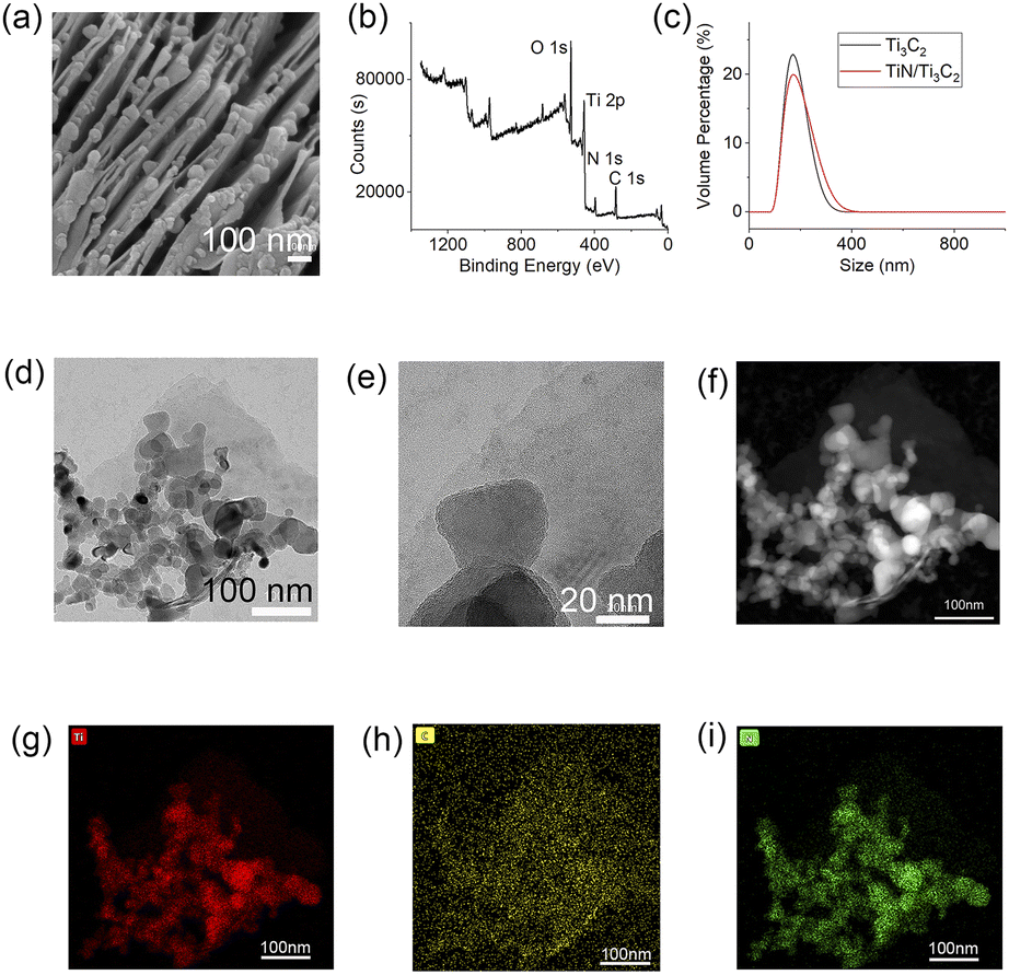
The TiN/Ti3C2 heterojunction was synthesized via a sonication-assisted intercalation approach. First, TiN nanoparticles with an average size of ∼20 nm were fabricated using a previously reported self-assembly-calcination method by our group.40 Ti3C2 nanosheets were obtained by employing a liquid exfoliation method in isopropanol. Then the TiN nanoparticles were dispersed in the Ti3C2 solution and sonicated at a power of 600 W for 12 hours, with the molar ratio of TiN to Ti3C2 reaching 1![[thin space (1/6-em)]](https://www.rsc.org/images/entities/char_2009.gif) :1. Scanning electron microscope (SEM) was employed to check the morphology of the heterojunction. As shown in Fig. 1a, nanoparticles whose sizes range from 10 to 30 nm were loaded onto the surface of layered materials, suggesting the successful intercalation of TiN nanoparticles into the Ti3C2 nanosheets. To investigate the elemental composition, full-scan X-ray photoelectron spectroscopy (XPS) spectrum (Fig. 1b) was collected confirming the major composition elements of the as-synthesized material are Ti, N and C, whose binding energies are located at ∼454 eV (Ti 3p), ∼398 eV (N 1s) and ∼285 eV (C 1s), respectively. The peak at ∼531 eV was assigned to O 1s, indicating that Ti3C2 might be partially oxidized, which is common in liquid exfoliation. Dynamic light scattering (DLS) analysis was further utilized to investigate the hydrodynamic size of the heterojunction material, with the result showing that the hydrodynamic size of the heterojunction is ∼170 nm, close to that of pure Ti3C2, which confirmed that the decoration of TiN nanoparticles on Ti3C2 occurred on the nanosheet surface (Fig. 1c). Transmission electron microscopy (TEM) images (Fig. 1d–f) demonstrated that the size of the heterojunction is consistent with the DLS result and the TiN nanoparticles were dispersed on the nanosheet surface instead of within the skeleton structure of Ti3C2. Energy-dispersive X-ray spectroscopy (EDS) (Fig. 1g and h) manifested Ti, C, and N elements were distributed well across the as-fabricated heterojunction material, consolidating that TiN nanoparticles were distributed well on the Ti3C2 surface with good uniformity.
:1. Scanning electron microscope (SEM) was employed to check the morphology of the heterojunction. As shown in Fig. 1a, nanoparticles whose sizes range from 10 to 30 nm were loaded onto the surface of layered materials, suggesting the successful intercalation of TiN nanoparticles into the Ti3C2 nanosheets. To investigate the elemental composition, full-scan X-ray photoelectron spectroscopy (XPS) spectrum (Fig. 1b) was collected confirming the major composition elements of the as-synthesized material are Ti, N and C, whose binding energies are located at ∼454 eV (Ti 3p), ∼398 eV (N 1s) and ∼285 eV (C 1s), respectively. The peak at ∼531 eV was assigned to O 1s, indicating that Ti3C2 might be partially oxidized, which is common in liquid exfoliation. Dynamic light scattering (DLS) analysis was further utilized to investigate the hydrodynamic size of the heterojunction material, with the result showing that the hydrodynamic size of the heterojunction is ∼170 nm, close to that of pure Ti3C2, which confirmed that the decoration of TiN nanoparticles on Ti3C2 occurred on the nanosheet surface (Fig. 1c). Transmission electron microscopy (TEM) images (Fig. 1d–f) demonstrated that the size of the heterojunction is consistent with the DLS result and the TiN nanoparticles were dispersed on the nanosheet surface instead of within the skeleton structure of Ti3C2. Energy-dispersive X-ray spectroscopy (EDS) (Fig. 1g and h) manifested Ti, C, and N elements were distributed well across the as-fabricated heterojunction material, consolidating that TiN nanoparticles were distributed well on the Ti3C2 surface with good uniformity.
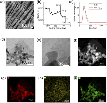 |
| | Fig. 1 (a) SEM image of TiN/Ti3C2 heterojunction. (b) XPS survey spectrum of TiN/Ti3C2 heterojunction. (c) DLS spectra of Ti3C2 and TiN/Ti3C2. (d–f) TEM images of TiN/Ti3C2 heterojunction with different scale bar. (g–i) EDX mapping results. | |
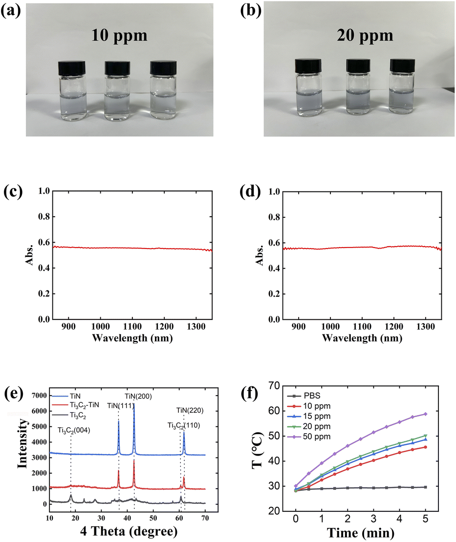
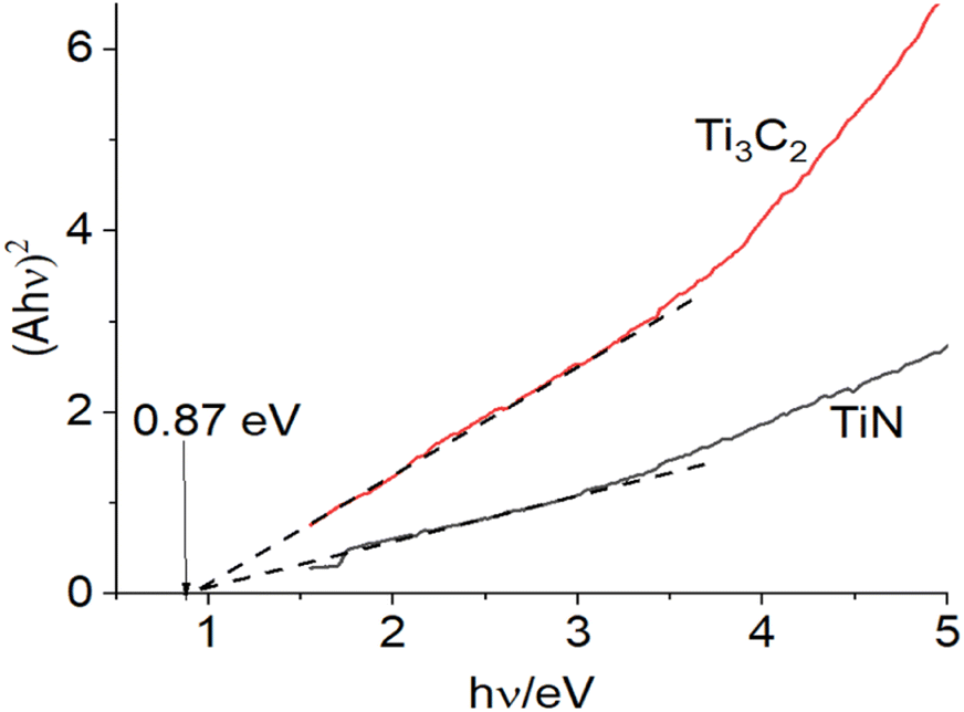
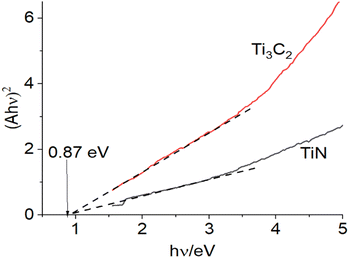
Photographs of TiN/Ti3C2 heterojunction after 1, 7, and 14 days were collected to check the stability (Fig. 2a and b). No obvious color decay was observed regardless of whether the concentration was 10 ppm or 20 ppm, suggesting increased resistance against the oxidation of Ti3C2 after forming heterojunctions with TiN nanoparticles even at such low concentration. Moreover, optical absorption performance at the communication bands (800–1400 nm) was studied, proving that the heterojunction was quite stable without oxidation or decomposition for 2 weeks (Fig. 2c and d). The absorption value reached almost 0.6 at merely 20 ppm for 14 days, indicating good photo-absorption performance within infrared range. The XRD patterns recorded in Fig. 2e depicted that only the peaks corresponding to the (111), (200), and (220) planes of TiN and (004) and (110) planes of Ti3C2 were detected for the heterojunction, indicating that the observed oxygen species did not form crystalline structures with Ti, which demonstrated that the optical behavior originated from TiN and Ti3C2, and that only a tiny amount of Ti was oxidized. Thereafter, a study on the photothermal behavior of the heterojunction after irradiation by laser at the near infrared zone (1064 nm) was performed, suggesting a highly efficient response to light at the communication bands. Finally, we performed the UV-vis DRS test to examine the bandgap of the two materials. As shown in Fig. 3, the bandgap values for both TiN and Ti3C2 are 0.87 eV.
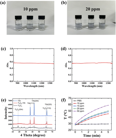 |
| | Fig. 2 (a and b) Photographs of TiN/Ti3C2 dispersion within two weeks. (c and d) Optical absorption spectra of the heterojunction with 20 ppm for day 1 and day 14. (e) XRD pattern of TiN/Ti3C2 heterojunction and the counterparts. (f) Photothermal effect of the heterojunction under after exposure to NIR laser for different time durations. (Laser wavelength: 1064 nm; laser power: 1 W cm−2). | |
 |
| | Fig. 3 The bandgap of TiN and Ti3C2. | |
2.2 Theory of the Kerr switch
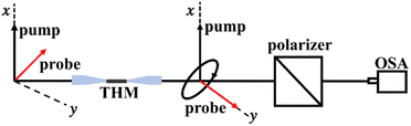
In the optical Kerr effect, a nonlinear phase shift of a strong control light is used to change the transmission of a weak signal in a nonlinear medium, and this can be used to make a shutter with picosecond response time. The operation principle of the Kerr switch is shown schematically in Fig. 4. At the input port, the control light and signal light are linearly polarized and the angle of polarization direction between the two is at 45°. In the absence of control light, the signal will be prevented from passing at the output port since the passable angle of an optical polarizer is orthogonally oriented with the state of polarization (SOP) of signal light. With the increase in control intensity, the refractive index of the signal light's parallel and vertical components will change due to birefringence induced by the control light. The phase difference between the two components manifests as a change in the SOP of the output signal light at the optical fiber output port. Therefore, a partial signal light can pass through the polarizer. Apparently, the transmissivity of the signal light is related to the intensity of the control light and can be controlled by simply adjusting the intensity of the control light. THM possesses a large nonlinear refractive index, which is very suitable as a nonlinear medium for the optical Kerr switch.
 |
| | Fig. 4 The operation principle of the Kerr switch. | |
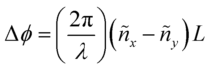
In Kerr switch, the wavelengths of the control and signal lights are different and ignores the losses from the optical fiber. After the signal light passes through the optical fiber with a length of L, the phase difference between the x and y components can be given by the following equation:
where
λ is the wavelength of the signal light, and
| ñx = nx + Δnx, ñy = ny + Δny |
due to modal birefringence, the linear part
nx and
ny of the refractive index are normally different. In addition, owing to the birefringence of control light, the nonlinear part Δ
nx and Δ
ny of the refractive index are also different. Considering the situation that control light polarizes along
x-axis, the
x component of the signal light is parallel to the control light with different wavelengths between them. In addition, if the contribution of self-phase modulation is ignored, there is
where |
Ep|
2 is the intensity of the control light and
n2 is the nonlinear refractive index. Owing to the difference in wavelengths between the control light and signal light when their SOP is orthogonal, Δ
ny can be expressed as
in case the third-order nonlinear effect is caused by pure electron, then
b = 1/3. Consequently, the phase difference of signal light can be determined as
It is noteworthy that when Δϕ = 0, the signal light is prevented by the polarizer completely, and when Δϕ ≠ 0, the optical fiber corresponds to a birefringent phase plate, a part of the signal light can transmit the polarizer. The brief relation between the transmissivity (Tp) and phase difference (Δϕ)of signal light can therefore be represented as
consequently, when Δ
ϕ is π or an odd multiple of π, the signal light will pass through the polarizer completely, and when Δ
ϕ is an even multiple of π, the signal light will be blocked totally.
2.3 Results and discussion
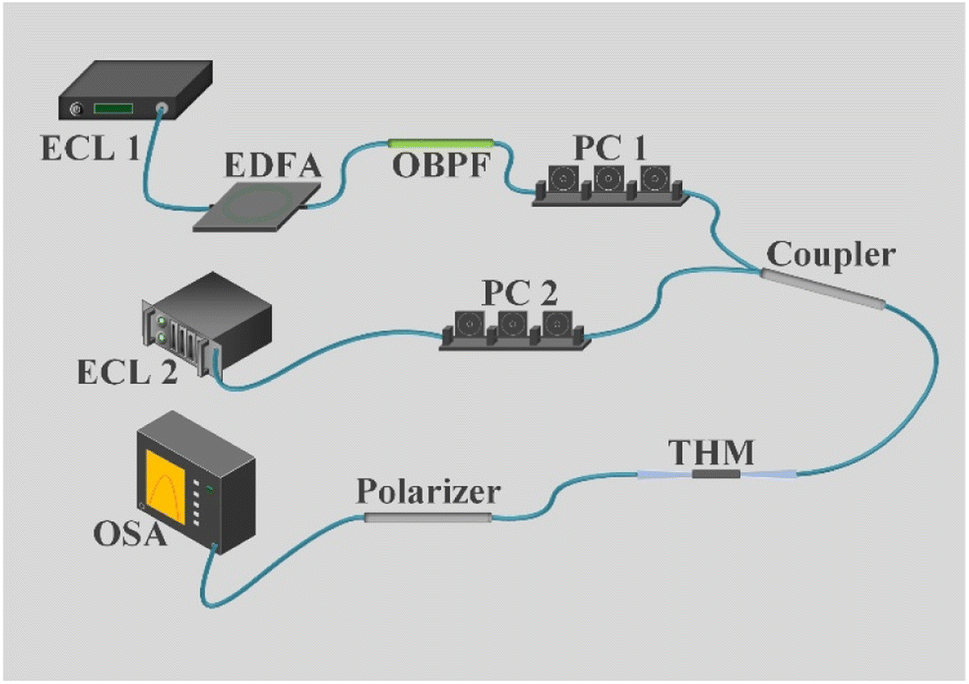
The experimental equipment of the optical Kerr switch is shown in Fig. 5. The wavelength of the signal light is fixed at 1550.12 nm, which is emitted by a tunable external cavity laser (ECL), which works in the c-band. The control light is emitted by an ECL, whose wavelength is fixed at 1552.09 nm. The control light was amplified by an erbium-doped fiber amplifier (EDFA) with a maximum output power of up to 260 mW. In order to sufficiently suppress the amplified spontaneous emission (ASE) noise arising from EDFA, an optical band-pass filter (OBPF) was inserted into the rear of the control light. Two polarization controllers are separately used here to adjust the SOP of the control and signal light. Then, the control and signal light were coupled to THM by a 3 dB coupler. To realize the maximum extinction ratio of the Kerr switch, the SOP of the signal light is orthogonal to the polarizer, and the angle of polarization direction between the control light and signal light is 45°.
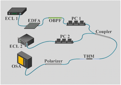 |
| | Fig. 5 The experimental device of THM-based optical Kerr switch. | |
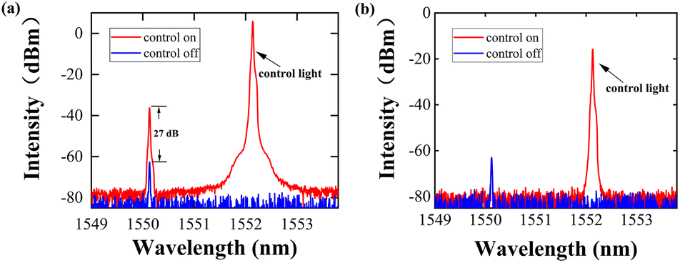
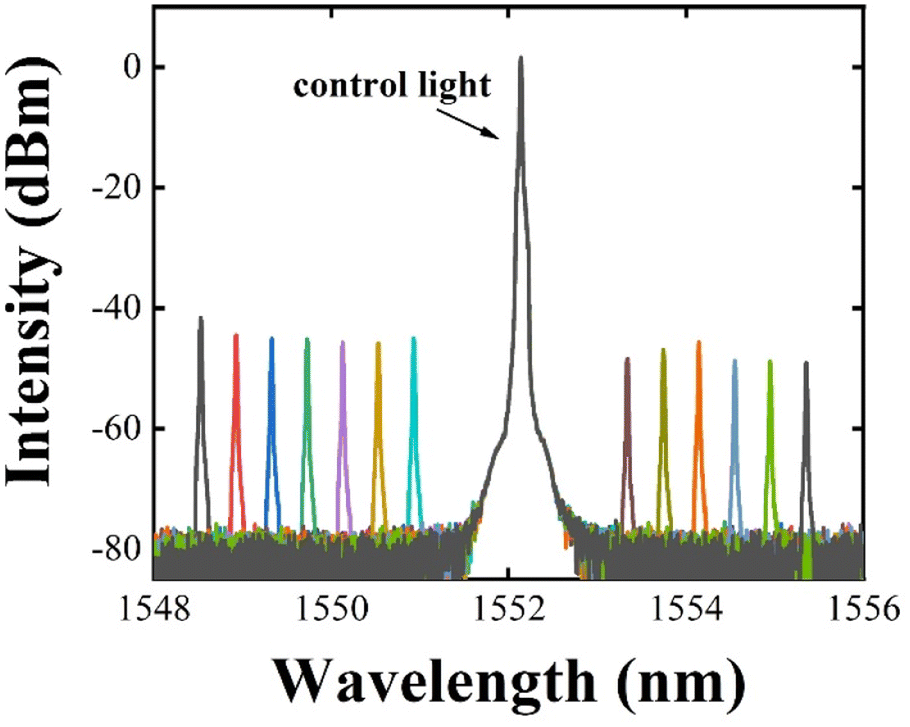
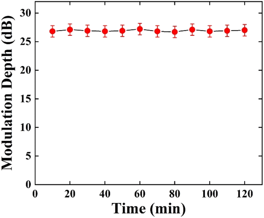
The experimental results show that there are two different states to the output signal light when the control light is turning on or off, as shown in Fig. 6(a). When there is no control light injected into the fiber, the intensity of the output signal light through the polarizer was ∼−63 dBm and the state of the signal light is switched off. On the contrary, when the control light is injected into the input port with a power of ∼200 mW, the intensity of the signal light increased to ∼−36 dBm, and the state of the signal light is switched on. If the control light is turned off at this time, the power of the signal light will immediately go back to ∼−63 dBm. Meanwhile, the power of the control light injected into the THM is only 75 mW owing to the insertion loss of the optical coupler. The measured difference between the two states of the signal light before and after the control light is turned on is ∼27 dB. For comparison, an optical Kerr switch based on a single-mode fiber (SMF) was also constructed, and the experimental results are shown in Fig. 6(b). At the output port, the power of the signal light was not changed regardless of whether the control light was turned on or off. The above-mentioned experimental results sufficiently illustrate that due to the nonlinear phase shift induced by the control light in THM, the SOP of the signal light rotated, indicating the power of the signal light changed after polarization. In addition, according to the theoretical analysis, the transmissivity of the signal light is apparently related to the input power of the control light. The maximum power of the control light amplified by EDFA can reach up to ∼260 mW, and the optical power injected into the THM could be adjusted from 0 to ∼95 mW. As shown in Fig. 7, when the power of the control light was gradually tuned from 4.9 mW to 256 mW, the intensity of the signal light increased correspondingly from ∼−60 dBm to ∼−33 dBm. This proves that the experimental results correspond to the theoretical analysis. The effect of different wavelengths of the signal light on the extinction ratio was explored by fixing the wavelength of the control light to 1552.09 nm and a power of 74 mW. The wavelength tuning range of the signal light was from 1548.6 nm to 1555.4 nm with a spacing of 0.5 nm. Before turning on the control light, the power of the signal light of all wavelengths passing through the polarizer was adjusted to the minimum that was ∼−65 dBm, as seen in Fig. 8, the intensity of the signal light with different wavelengths increased from ∼−65 dBm to ∼−45 dBm when the control light turned on. On account of it being necessary to adjust the SOP of the signal light with different wavelengths separately to control the power passing through the polarizer, there was an error of ∼5 dB with the state of the signal light is switching on. We also conducted a stability test on the device for a duration of 2 hours, and the results are shown in Fig. 9. The measurements were taken at 10 minutes intervals, and it can be observed from the graph that the device consistently maintained a modulation depth of around 27 decibels throughout the two hour period, demonstrating high stability. From Table 1, it can be observed that in relevant experiments the material reported in this study achieves the highest modulation depth, accompanied by relatively low levels of required control power. Remarkably, even when stored for over a month under room temperature conditions, the device continues to operate reliably. This fully demonstrates that compared to other material-based microfibers,35–39 THM significantly improved the performance of the Kerr switch.
 |
| | Fig. 6 The change of intensity of output signal light when control light is on or off (a) with material and (b) without material. | |
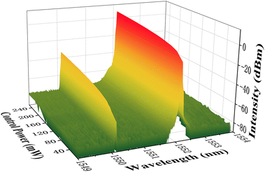 |
| | Fig. 7 The output spectrum of signal light when slowly increases the power of control light from 4.9 mW to ∼256 mW. | |
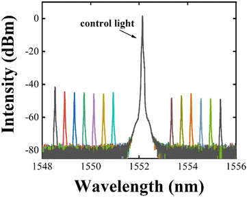 |
| | Fig. 8 The output spectra versus the wavelength of signal light tuned from 1548.58 nm to 1555.46 nm while wavelength of control light was fixed at 1552.09 nm. | |
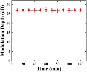 |
| | Fig. 9 Modulation depth variation over 2 hours at 10 minutes intervals. | |
Table 1 Performance parameters of different materials in all-optical Kerr switch
| Sample |
Modulation depth (dB) |
Stability |
Nonlinear refractive index (cm2 W−1) |
Control power (mW) |
| TCM: topological insulator-coated microfiber. BP: black phosphorus. FLA: few-layer antimonene. FLB: few-layer bismuthate. BPQD: black phosphorus quantum dot. THM: TiN/Ti3C2 heterojunction-coated microfiber. |
| TCMa |
14 |
— |
9.16 × 10⁻⁶ |
80 |
| BPb |
26 |
<2 days41 |
10−9 (ref. 42) |
300 |
| FLAc |
13 |
— |
1.22 × 10⁻¹⁵ |
316 |
| FLBd |
22 |
— |
— |
220 |
| BPQDe |
20 |
<2 weeks43 |
1.25 × 10⁻¹⁵ |
160 |
| THMf |
27 |
>1 month |
— |
200 |
3. Conclusions
In this study, we successfully prepared TiN/Ti3C2 heterojunction-coated microfiber and verified its application in an all-optical Kerr switch. The Kerr switch exhibits high stability, and its extinction ratio shows a positive correlation with the control power. The extinction ratio remains stable at 25–27 dB at different wavelengths of signal light and can reach up to 27 dB at a control power of 200 mW. Because it utilizes the nonlinear effect of light, it has the potential to achieve high-speed all-optical modulation. The results indicate that the Kerr switch has broad prospects in all-optical signal processing.
Author contributions
Conceptualization, Ke-Wang and Qidong-Liu; data curation, Ni-Fan, Yujie-Wang and Bin-Zhang; formal analysis, Ke-Wang, Qidong-Liu, Zhenhong-Wang and Yufeng-Song; funding acquisition, Ke-Wang, Qidong-Liu, Zhenhong-Wang and Yufeng-Song; investigation, Y.-T. Y.; methodology, Ke-Wang and Qidong-Liu; project administration, Ke-Wang; resources, Yujie-Wang and Bin-Zhang; software, Qidong-Liu; writing—original draft, Ke-Wang and Qidong-Liu; writing—review & editing, Zhenhong-Wang, Yufeng-Song, Haiming-Huang, Ni-Fan, Yujie-Wang and Bin-Zhang; all authors have read and agreed to the published version of the manuscript.
Conflicts of interest
The authors declare that they have no significant conflict of interest.
Acknowledgements
This research was funded by the National Natural Science Foundation of China (grant no. 52203335, 62005178), Natural Science Foundation of Guangdong Province (grant no. 2023A1515010093, 2020A1515110749), and Shenzhen Fundamental Research Program (grant no. KCXFZ20201221173413038, JCYJ20190808112401659, JCYJ20190808143611709, JCYJ20200109105216803 and JCYJ20220809170611004).
Notes and references
- N. S. Patel, K. A. Rauschenbach and K. L. Hall, IEEE Photonics Technol. Lett., 1996, 8(12), 1695–1697 Search PubMed.
- J. Wang and J. M. Kahn, IEEE Photonics Technol. Lett., 2004, 16(5), 1397–1399 CrossRef.
- K. S. Novoselov, A. K. Geim and S. V. Morozov, Science, 2004, 306, 666–669 CrossRef CAS PubMed.
- F. Bonaccorso, Z. Sun, T. Hasan and A. C. Ferrari, Nat. Photonics, 2010, 4, 611–622 CrossRef CAS.
- Q. Bao, H. Zhang, Y. Wang, Z. Ni, Y. Yan, Z. X. Shen, K. P. Loh and D. Y. Tang, Adv. Funct. Mater., 2009, 19, 3077–3083 CrossRef CAS.
- G. Eda and S. A. Maier, ACS Nano, 2013, 7, 5660–5665 CrossRef CAS PubMed.
- Z. C. Luo, M. Liu, Z. N. Guo, X. F. Jiang, A. P. Luo, C. J. Zhao, X. F. Yu, W. C. Xu and H. Zhang, Opt. Express, 2015, 23, 20030–20039 CrossRef CAS PubMed.
- M. Liu, X. Yin, E. Ulin-Avila, B. Geng, T. Zentgraf, L. Ju, F. Wang and X. A. Zhang, Nature, 2011, 474, 64–67 CrossRef CAS PubMed.
- Q. H. Wang, K. Kalantar-Zadeh, A. Kis, J. N. Coleman and M. S. Strano, Nat. Nanotechnol., 2012, 7, 699–712 CrossRef CAS PubMed.
- M. Zhang, R. C. T. Howe, R. I. Woodward, E. J. R. Kelleher, F. Torrisi, G. H. Hu, S. V. Popov, J. R. Taylor and T. Hasan, Nano Res., 2015, 8, 1522–1534 CrossRef CAS.
- S. Wang, H. Yu, H. Zhang, A. Wang, M. Zhao, Y. Chen, L. Mei and J. Wang, J. Adv. Mater., 2014, 26, 3538–3544 CrossRef CAS PubMed.
- H. Li, J. Wu, Z. Y. Yin and H. Zhang, Acc. Chem. Res., 2014, 47, 1067–1075 CrossRef CAS PubMed.
- Z. Y. Yin, H. Li, L. Jiang, Y. M. Shi, Y. H. Sun, G. Lu, Q. Zhang, X. D. Chen and H. Zhang, ACS Nano, 2012, 6, 74–80 CrossRef CAS PubMed.
- H. Zhang, ACS Nano, 2015, 9, 9451–9469 CrossRef CAS PubMed.
- D. Wei, Y. Liu, Y. Wang, H. Zhang, L. Huang and C. Yu, Nano Lett., 2009, 9, 1752–1758 CrossRef CAS PubMed.
- H. Liu, Y. Liu and D. Zhu, J. Mater. Chem., 2011, 21, 3335–3345 RSC.
- X. Dong, D. Fu, W. Fang, Y. Shi, P. Chen and L. J. Li, Small, 2009, 5, 1422–1426 CrossRef CAS PubMed.
- C. Koos, P. Vorreau, T. Vallaitis, P. Dumon, W. Bogaerts, R. Baets, B. Esembeson, I. Biaggio, T. Michinobu, F. Diederich, W. Freude and J. Leuthold, Nat. Photonics, 2009, 3, 216–219 CrossRef CAS.
- A. E. Willner, S. Khaleghi, M. R. Chitgarha and O. F. Yilmaz, J. Lightwave Technol., 2014, 32, 660–680 Search PubMed.
- P. F. She, Y. Y. Qin, X. Wang and Q. Zhang, Adv. Mater., 2022, 34, 2101175 CrossRef CAS PubMed.
- S. Ling, C. Zhang, C. Ma, Y. Li and Q. Zhang, Adv. Funct. Mater., 2023, 33, 2208320 CrossRef CAS.
- M. Liu, Z. Wei, A. Luo, W. Xu and Z. Luo, Nanophotonics, 2020, 9(9), 2641–2671 CrossRef.
- G. Sobon, J. Sotor, I. Pasternak, A. Krajewska, W. Strupinski and K. M. Abram-Ski, Opt. Express, 2013, 21, 12797–12802 CrossRef CAS PubMed.
- P. Yan, A. Liu and Y. Chen, Opt. Mater. Express, 2015, 5, 479–489 CrossRef.
- H. Zhang, D. Y. Tang, L. M. Zhao, Q. L. Bao and K. P. Loh, Opt. Express, 2009, 17, 17630–17635 CrossRef CAS PubMed.
- H. D. Xia, H. P. Li, C. Y. Lan, C. Li, X. X. Zhang, S. J. Zhang and Y. Liu, Opt. Express, 2014, 22, 17341 CrossRef PubMed.
- J. T. Wang, H. Chen and Z. K. Jiang, Opt. Lett., 2018, 43, 1998 CrossRef CAS PubMed.
- M. Liu, Z. Wei, A. Luo, W. Xu and Z. Luo, Nanophotonics, 2020, 9(9), 2641–2671 CrossRef.
- Q. L. Bao and K. P. Loh, ACS Nano, 2012, 6, 3677–3694 CrossRef CAS PubMed.
- Y. Z. Wang, F. Zhang, X. Tang, X. Chen and Y. X. Chen, Laser Photonics Rev., 2018, 12, 1800016 CrossRef.
- J. Zheng, X. Tang, Z. Yang, Z. Liang, Y. Chen, K. Wang, Y. Song, Y. Zhang, J. Ji, Y. Liu, D. Fan and H. Zhang, Adv. Opt. Mater., 2017, 5, 1700026 CrossRef.
- K. Yadav, R. Sangwan, N. Poonam, D. Mohan and S. Sanghi, J. Mater. Sci.: Mater. Electron., 2023, 34, 1161 CrossRef CAS.
- M. Asobe, Opt. Fiber Technol., 1997, 3, 142 CrossRef.
- Y. Chen, T. F. Xu, X. Shen, R. P. Wang, S. F. Zong, S. X. Dai and Q. H. Nie, J. Alloys Compd., 2013, 580, 578 CrossRef CAS.
- S. Chen, L. Miao, X. Chen, Y. Chen, C. Zhao, S. Datta, Y. Li, Q. Bao, H. Zhang, Y. Liu, S. Wen and D. Fan, Adv. Opt. Mater., 2015, 3, 1769–1778 CrossRef CAS.
- J. Zheng, Z. S. C. Yang, Z. Liang and Z. Han, ACS Photonics, 2017, 4(6), 1466–1476 CrossRef CAS.
- Y. Song, Y. Chen, X. Jiang, W. Liang, K. Wang, Z. Liang, Y. Ge, F. Zhang, L. Wu, J. Zheng, J. Ji and H. Zhang, Adv. Opt. Mater., 2018, 6, 1701287 CrossRef.
- K. Wang, J. Zheng, H. Huang, Y. Chen, Y. Song, J. Ji and H. Zhang, Opt. Express, 2019, 27, 16798–16811 CrossRef CAS PubMed.
- K. Wang, Y. X. Chen, J. L. Zheng, Y. Q. Ge, J. H. Ji, Y. F. Song and H. Zhang, Nanotechnology, 2019, 30, 415202 CrossRef CAS PubMed.
- Y. T. Yang, H. W. Wu, Y. Zou, X. Y. Fang, S. Li, Y. F. Song, Z. H. Wang and B. Zhang, Nanomaterials, 2022, 12(13), 2280 CrossRef CAS PubMed.
- M. Edmonds, A. Tadich, A. Carvalho, A. Ziletti, K. O'Donnell, S. Koenig, D. Coker, B. Özyilmaz, A. C. Neto and M. Fuhrer, ACS Appl. Mater. Interfaces, 2015, 7, 14557–14562 CrossRef CAS PubMed.
- X. X. Jin, W. L. Bao, H. Zhang, Z. Zheng and M. Zhang, Photonics Res., 2022, 10, 503–508 CrossRef.
- J. D. Wood, S. A. Wells, D. Jariwala, K. S. Chen, E. K. Cho, V. K. Sangwan, X. Liu, L. J. Lauhon, T. J. Marks and M. C. Hersam, Nano Lett., 2014, 14(12), 6964–6970 CrossRef CAS PubMed.
|
| This journal is © The Royal Society of Chemistry 2023 |
Click here to see how this site uses Cookies. View our privacy policy here. 
 Open Access Article
 This Open Access Article is licensed under a Creative Commons Attribution-Non Commercial 3.0 Unported Licence
 *a
*a