 Open Access Article
Encapsulation and thermal properties of composite phase change materials based on cobalt/nitrogen double-doped ZIF-67 derived carbon
Yanteng Lia,
Yan Gao *abc,
Xuankai Cao
 a,
Xing Rongd,
Baoming Chena,
Guohong Tianc,
Zishang Zhue,
Xudong Zhaoe and
Zhanchao Zhangb
aShandong Technology Innovation Center of Carbon Neutrality, School of Thermal Engineering, Shandong Jianzhu University, Jinan, 250013, China. E-mail: gaoyan.sdu@hotmail.com
bShandong Province Jinan Ecological and Environmental Monitoring Center, Jinan, 250101, China
cSchool of Mechanical Engineering Sciences, University of Surrey, Guildford, Surrey, GU2 7XH, UK
dShandong Luqiao Group Equipment Technology Development Company, Jinan, China
eEnergy and Environmental Institute, University of Hull, Hull, HU6 7RX, UK
First published on 7th September 2023
Abstract
To solve the problems of easy leakage and weak thermal conductivity of single-phase change material, in this experiment, cobalt/nitrogen-doped ZIF-67 derived carbon (CoN-ZIF-Cx) was constructed as the carrier material, and paraffin was used as the phase change core material to construct thermally enhanced shaped composite phase change materials (P0.6@CoN-ZIF-Cx). The composite PCMs were characterized using scanning electron microscopy, isothermal nitrogen adsorption–desorption, X-ray diffraction, and Fourier infrared spectroscopy, and their performance was evaluated using transient planar heat source techniques, differential scanning calorimetry, and thermal cycling tests. The results indicated that the impurities of the acid-washed porous carbon material were reduced and the loading of the paraffin was 60%, and the prepared P0.6@CoN-ZIF-Cx had an excellent thermal performance. Among them, P0.6@CoN-ZIF-C3 has the melting and crystallization enthalpy of 71.03 J g−1 and 68.81 J g−1. The thermal conductivity is 0.4127 W m−1 K−1, a 46.19% thermal conductivity improvement compared with pure paraffin. It still has favourable thermal storage capacity after 50 cycles without paraffin leakage during the phase transition.
1. Introduction
In recent years, non-renewable resources have been gradually depleted after a long period of development and utilization, causing severe environmental and climate effects, leading to an energy crisis and critical environmental challenges.1 In response to these issues, countries around the world have adopted a variety of measures. Among them, promoting clean energy, improving energy efficiency, developing alternative energy sources, and promoting international energy cooperation are significant ways to alleviate the fossil energy crisis and promote sustainable development.2 The current clean, renewable energy, mainly hydrogen, wind, and solar energy, are susceptible to the influence of various factors such as time, environment, and climate, and have the disadvantages of intermittency, locality, and instability,3,4 which leads to the mismatch between energy supply and demand within time and space that curbs the improvement of energy utilization.5Thermal Energy Storage (TES) technology aims to store thermal energy for usage across times and regions. The different principles of heat storage can be divided into sensible heat storage, phase change heat storage, and thermochemical heat storage.6 Latent heat storage (LTES) is an effective means of improving energy utilization and extending thermal energy applications by utilizing thermal storage materials for heat storage and release, which merely experience changes in the physical state during heat storage and release and can be reused repeatedly.7,8
Phase change materials (PCMs) can undergo phase transformation and provide latent heat at a constant temperature, and the transformation process is known as the phase transition process.9 Utilizing PCMs for latent heat storage is one of the most excellent methods. Compared with sensible heat storage and chemical storage systems, PCMs for latent heat storage can achieve higher energy storage density while possessing phase change isothermal properties, which have significant advantages in heat transfer optimization, hot spot control, and other aspects.10,11 PCMs could be classified into four categories: solid–solid, solid–gas, gas–liquid, and solid–liquid phase change according to the phase change.12 In particular, solid–liquid phase change materials have higher energy storage density, possess suitable phase change temperature ranges, and the volume change is typically less than 10% during the phase change process,13 which is widely applied to various fields such as energy storage,14 waste heat utilization,15 and material fabrication.16
As a saturated alkane, paraffin has higher latent heat and suitable phase change temperature, and it can be directly obtained as a by-product of petroleum in industrial fields, which is non-toxic, non-hazardous, and cost-effective, so it is one of the most preferred materials for application in LTES systems.17,18 However, pure paraffin must also overcome the same challenges as many PCMs, such as low thermal conductivity and easy leakage, which severely impedes its application in thermal energy storage systems.19
To solve the above problems, scientists from various countries have conducted extensive research, such as introducing porous materials with different properties as carrier media, packaging and storing PCMs, and developing composite PCMs with stable shapes and improved thermal conductivity. Wang et al.20 graphitized the hollow carbon fibre in asphalt, extracted the hollow graphite fibre (HGF), and adsorbed paraffin to prepare the HGF/PCM composite, which has a latent heat of 160 J g−1 and a thermal conductivity of 2.5 W m−1 K−1. Compared with pure paraffin, the thermal conductivity is increased by more than 680%. Wang et al.21 modified copper foam with high-density nanorods (NR) to provide uniform attachment points for ZIF-67 derived porous carbon (PC) that prevent PC aggregation and then prepared SA@PC/NRs composite phase change materials with a core material of stearic acid (SA). This hierarchical composite has a stearic acid loading of 42% and a thermal conductivity of 0.81 W m−1 K−1, dramatically improving the material's energy storage efficiency, durability, and shape stability. Atinafu et al.22 prepared N-doped porous carbon (NPC–Al) with NH2-MIL-53 (Al) as a precursor and obtained composite PCMs by compounding with polyethylene glycol (PEG). The NPC-Al carrier material exhibited large and regular pore size, large specific surface area, and high nitrogen content. The results show that the loading of N-doped carbon materials on the peg is only 85%, and the melting enthalpy is 148.1 J g−1; The N-modified carbon material can increase the peg loading to 90%, the melting enthalpy to 168.3 J g−1, and the thermal conductivity to 0.41 W m−1 K−1, which is 52% higher than that of the n-doped material.
Metal–Organic Frameworks (MOFs) are a new type of porous material, self-assembled from metal ions and organic ligands, and are organic–inorganic hybrid materials.23 The interaction between metal ions and organic ligands forms the pore structure of MOFs. This particular structure makes MOFs have good thermal stability, chemical stability, and mechanical properties and can withstand extreme conditions such as high temperature and high pressure.24 In addition, MOFs materials also have many advantages, such as large specific surface area, adjustable pore size, directional tailoring, and post modification, which are widely used in adsorption catalysis,25 energy storage,26 gas storage and separation,27 and other fields. In recent years, MOFs have become an emerging carrier for the preparation of composite PCMs materials, MOFs-based composite PCMs have attracted much attention; however, most MOFs materials have relatively low thermal conductivity, which is difficult to fulfil the problem of improving the thermal conductivity of composite PCMs.28 The porous carbon-based material derived from MOFs can be obtained by calcining at high temperatures in an inert atmosphere with MOFs as the precursor. The derived porous carbon-based material can inherit the pore structure of the MOFs precursor through a specific process, and the pore diameter can also be enlarged.29 Using MOFs containing specific metal atoms as precursors, the multi-level porous structure doped with metal particles can be obtained by calcination, in which the metal ions will be partially reduced in the carbonization process, and the reduced metal can in turn improve the graphitization degree of carbon.30 By introducing specific heteroatoms or functional groups or further modifying the crystal structure, MOFs derived carbon materials can be endowed with higher porosity and rich active sites.31 Composite PCMs using MOFs derived from porous carbon materials as carriers generally have the effect of improved thermal conductivity.32
As a typical representative of MOFs, ZIF-67 is a metal organic framework self-assembled by metal cobalt and imidazole ligands. Compared with other MOFs, ZIF-67 can be prepared by hydrothermal method with low cost,33 and the imidazole ligand in ZIF-67 introduces nitrogen element, which can obtain nitrogen in situ doped carbon after carbonization. The nitrogen based functional group is easy to generate hydrogen bond with the phase change core material, which plays a role in restraining leakage during the phase change process of the phase change core material, and improves the thermal conductivity.34
In this study, ZIF-67 nanocrystals were prepared by solvothermal method. Cobalt/nitrogen-doped ZIF-67-derived porous carbon materials were obtained by high-temperature calcination in the N2 atmosphere, and the pickling time was controlled to remove excess impurities. The ZIF-67-derived porous carbon material was used as the carrier to encapsulate the paraffin core effectively, and the stable shape of high thermal conductivity composite PCMs was prepared. Various characterization techniques were used to study the microstructure of the material and the thermal properties of the composite PCMs, explore the optimal paraffin load to obtain the maximum energy storage and solve the problems of easy leakage and low thermal conductivity of the paraffin core.
2. Research methods
2.1. Experimental materials and equipment
2.2. Samples preparation
where: m1 and m2 are the mass of paraffin and carrier material respectively, g.
2.3. Characterization of physical and chemical properties
The specific surface area, pore volume, pore structure, and other parameters of the samples were detected by the automatic specific surface area analyzer (Belsorp-max, MicrotracBEL, Japan). The samples were degassed at 150 °C for 24 h, and the N2 adsorption–desorption isotherm curve was obtained at 77 K. The specific surface area and pore structure were calculated by Brunauer–Emmet–Teller (BET) formula and Barrett–Joyner–Halenda (BJH) model, respectively.36Brunauer–Emmet–Teller(BET):
Barrett–Joyner–Halenda(BJH):
The phase and crystal structure of the samples were analyzed by X-ray diffractometer (Smartlab 9, Rigaku, Japan). At room temperature, the scanning speed was 20 deg min−1, the scanning step was 0.01°, and the scanning range was 5° to 90°. Fourier determined the functional groups of PCMs samples transform infrared spectrometer (Tensor27, Bruker, German). The test range was 500 cm−1 to 4000 cm−1, and the spectral resolution was 4 cm−1. Scanning electron microscopy (SU8010, Zeiss, German) was used to detect the micromorphology of the samples, with a maximum resolution of 1 nm and an acceleration voltage of 0.1 kV to 30 kV. In addition, the samples should be diluted appropriately and sprayed with gold before testing.
The thermal storage properties of the composite PCMs were determined using a differential scanning calorimeter (TA Q20, Mettler Toledo, Switzerland), with composite PCMs heated and cooled at the rate of 10 K min−1 between 30 °C and 90 °C in N2 atmosphere and the N2 flow rate maintained at 5 ml min−1. The thermal conductivity of composite PCMs was determined by the transient planar source technique (TPS 2500S, HotDisk, Switzerland). The test power was 30 mW, and the test time was 20 s. The pressed composite PCMs samples were placed on filter paper and heated in a 70 °C drying oven for 30 min. The sample morphology was observed after cooling to room temperature, and the sample quality before and after heating was recorded. The chemical structure and thermal storage performance of the samples heated 50 times were analyzed again to detect the thermal cycle stability of the composite PCMs.
3. Results and discussion
3.1. Pore structure analysis
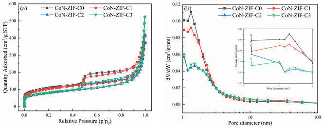
To evaluate the pore structure of different carrier materials, N2 adsorption–desorption experiments were carried out. The N2 adsorption–desorption isotherms and pore size distribution of CoN-ZIF-Cx were shown in Fig. 1a and b, respectively, and the detailed specific surface area, pore volume, and average pore size of CoN-ZIF-Cx were summarized in Table 1. As seen in Fig. 1a, CoN-ZIF-Cx all exhibit type IV N2 adsorption–desorption isotherms and produce H3-type hysteresis loops, indicating the presence of CoN-ZIF-Cx intermediate pores.| Samples | Surface area (m2 g−1) | Pore volume (cm3 g−1) | Average pore diameter (nm) |
|---|---|---|---|
| CoN-ZIF-C0 | 409.12 | 0.537 | 5.25 |
| CoN-ZIF-C1 | 398.80 | 0.609 | 6.11 |
| CoN-ZIF-C2 | 280.46 | 0.625 | 8.91 |
| CoN-ZIF-C3 | 290.74 | 0.777 | 10.69 |
With the increase in pickling time, CoN-ZIF-Cx exhibited higher adsorption in the high-pressure region with P/P0 > 0.9, indicating that the material's pore structure was expanded after prolonged pickling.37 Fig. 1b further demonstrates the expanded pore size range of the CoN-ZIF-Cx material, as shown in Table 1, where the pore volume of the material increases from 0.537 cm3 g−1 to 0.777 cm3 g−1 and the average pore size increases from 5.25 nm to 10.69 nm with increasing acid washing time. In addition, as can be seen from Fig. 1b, CoN-ZIF-Cx presents a hierarchical pore structure with micropores/mesopores. Micropores are distributed between 0–2 nm, mainly between 1–2 nm, and mesopores are distributed between 2-50 nm, mainly between 2–10 nm. Micropores could produce a strong adsorption force on paraffin, maintain the stability of composite PCMs, and effectively prevent the leakage of phase change core material.38 Mesopores could provide more phase change space for paraffin, substantially increase the paraffin loading and maintain high thermal storage efficiency.39 The results show that the sintered MOFs materials still have good pore structure.
In order to study the pore structure changes after paraffin encapsulation, N2 adsorption desorption experiments were carried out on P0.6@CoN-ZIF-C3 with the best performance. Fig. 2a and b shows the N2 adsorption desorption isotherm and pore size distribution of P0.6@CoN-ZIF-C3 respectively, and the detailed specific surface area, pore volume and average pore size of P0.6@CoN-ZIF-C3 are summarized in Table 2. The specific surface area of the composite phase change material is 4.99 m2 g−1, and the pore volume is 0.041 cm3 g−1, which is significantly lower than that of the carrier material. This indicates that paraffin can be adsorbed by the carrier material, and ZIF-67 derived carbon material is a good carrier material for composite PCMs.40 In addition, it can be seen from Fig. 2b that due to the filling of paraffin, the pores of the phase change material after composite are significantly reduced, and the pore size distribution is significantly reduced. The 0–1 nm micropore structure no longer exists, and the number of 1–2 nm micropores and some mesopores decreases sharply, so the average pore size of the composite phase change material has been greatly improved.
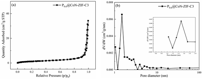 | ||
| Fig. 2 BET test of P0.6@CoN-ZIF-C3 (a) N2 adsorption–desorption isotherm (b) pore size distribution. | ||
| Sample | Surface area (m2 g−1) | Pore volume (cm3 g−1) | Average pore diameter (nm) |
|---|---|---|---|
| P0.6@CoN-ZIF-C3 | 4.99 | 0.041 | 32.5 |
3.2. X-ray diffraction analysis
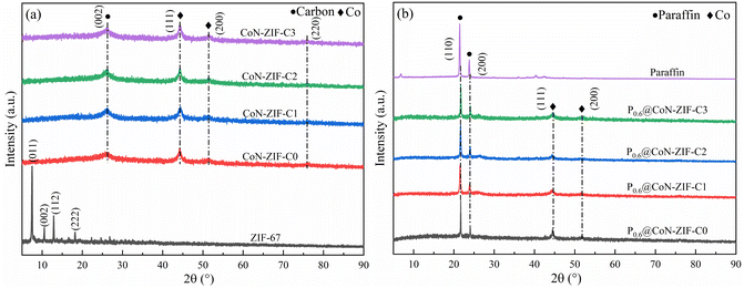
The XRD pattern of CoN-ZIF-Cx carrier material was shown in Fig. 3a. If indicated, ZIF-67 shows the prominent characteristic peaks in the (011), (002), (112), and (222) planes around 2θ = 7.49°, 10.54°, 12.88° and 18.20°.41 The ZIF-67 crystals underwent a structural transformation after calcination at high temperatures. The prominent characteristic peaks of the carbonized CoN-ZIF-Cx samples were located at 44.15°, 51.42°, and 75.81°, corresponding to the (111), (200), and (220) crystal planes of cobalt crystals,42 in addition to the typical characteristic peak at 2θ = 26.14° corresponding to the (002) crystal planes of graphitic carbon,42 the presence of cobalt monomers and graphitic carbon can effectively improve the thermal conductivity of the material. After pickling, the CoN-ZIF-Cx carrier material still showed a one-to-one corresponding characteristic derivative peak, indicating that pickling did not damage the main structure of the material.The XRD patterns of the composite PCMs were shown in Fig. 3b. The paraffin exhibited two distinct characteristic peaks at 2θ = 21.43° and 23.85°, corresponding to the (110) and (200) crystallographic planes, respectively.43 The spectrum of P0.6@CoN-ZIF-Cx contains the characteristic peaks of paraffin in addition to the characteristic peaks of CoN-ZIF-Cx carrier material, which indicates that the composite PCMs were successfully synthesized, except that no novel characteristic diffraction peaks were generated, meaning that the composite process of paraffin with CoN-ZIF-Cx carrier material was only a physical process without any chemical changes. In addition, the characteristic peaks of the paraffin portion of the P0.6@CoN-ZIF-Cx spectrum were below those of the paraffin itself due to factors such as nano-constraint between the paraffin and CoN-ZIF-Cx carrier materials.
3.3. Fourier infrared spectral analysis
The FTIR spectra of ZIF-67 and its derived carbon materials were shown in Fig. 4a. Most of the diffraction peaks in ZIF-67 come from imidazole ligands. The stretching and bending modes of the imidazole ring cause infrared characteristic peaks at 600 cm−1 to 1500 cm−1.44 The out-of-plane vibration of the plane and imidazole ring causes characteristic peaks below 800 cm−1. The characteristic peaks detected at about 1423.41 cm−1 and 1305.76 cm−1 were attributed to the stretching vibration of the imidazole ring.45 In addition, two infrared characteristic peaks of 1141.82 cm−1 and 991.37 cm−1 were caused by the stretching vibration of the C–N bond and the stretching vibration of Co–N, and the stretching vibration of C![[double bond, length as m-dash]](https://www.rsc.org/images/entities/char_e001.gif) N bond causes one characteristic peak of 1579.64 cm−1.46 The detection of infrared functional groups proved that ZIF-67 material was successfully synthesized, and there was apparent cobalt/nitrogen doping. No pronounced characteristic peaks were observed in the infrared spectra of the carbonized CoN-ZIF-Cx sample, indicating that its functional groups had been wholly decomposed during high-temperature treatment.
N bond causes one characteristic peak of 1579.64 cm−1.46 The detection of infrared functional groups proved that ZIF-67 material was successfully synthesized, and there was apparent cobalt/nitrogen doping. No pronounced characteristic peaks were observed in the infrared spectra of the carbonized CoN-ZIF-Cx sample, indicating that its functional groups had been wholly decomposed during high-temperature treatment.
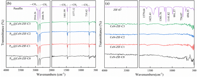 | ||
| Fig. 4 FTIR spectrum of the material before and after compounding (a) CoN-ZIF-Cx (b) P0.6@CoN-ZIF-Cx. | ||
Fig. 4b shows the FTIR spectra of composite PCMs (P0.6@CoN-ZIF-Cx). The infrared absorption peaks of paraffin at 2916.26 cm−1 and 1461.99 cm−1 represent the symmetric stretching and deformation vibrations of –CH3, respectively, and the infrared absorption peaks at 2848.76 cm−1 and 1377.12 cm−1 represent the stretching and deformation vibrations of –CH2, respectively. In addition, the infrared absorption peak at 719.42 cm−1 was caused by the in-plane rocking vibration of –CH2.47
The characteristic infrared absorption peaks of paraffin could be found in the FTIR spectrum of P0.6@CoN-ZIF-Cx, and the characteristic peaks are sharp and robust without any deviation, indicating excellent chemical compatibility between paraffin and CoN-ZIF-Cx. The composite PCMs did not produce new infrared absorption peaks, meaning only physical changes occurred, consistent with the XRD results. In addition, as the hydrogen bonding between the paraffin and carbon materials and the van der Waals force constraint, there was a significant reduction in the characteristic absorption peak of the paraffin corresponding to the composite P0.6@CoN-ZIF-Cx material.48 For different pickling times of carbon materials, the characteristic absorption peaks of paraffin in P0.6@CoN-ZIF-C0, P0.6@CoN-ZIF-C1, and P0.6@CoN-ZIF-C2 were more extensive than those in P0.6@CoN-ZIF-C3 samples, which might be caused by partial leakage of paraffin in P0.6@CoN-ZIF-C0, P0.6@CoN-ZIF-C1, and P0.6@CoN-ZIF-C2.
3.4. Microscopic morphological analysis
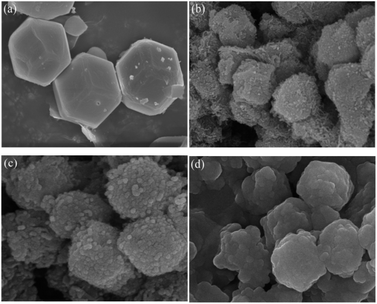
The microscopic morphologies of ZIF-67, CoN-ZIF-C0, CoN-ZIF-C3, and P0.6@CoN-ZIF-C3 were observed using scanning electron microscopy (SEM), and the results were shown in Fig. 5. ZIF-67 showed a dodecahedral structure and a relatively smooth surface. After carbonization, the surface roughness of the CoN-ZIF-C0 sample increased dramatically, and worm-like striated particles were attached. Fig. 5c shows that on the surface of the CoN-ZIF-C3 sample, the particles were evident after a long time of acid washing, and the remaining impurities were reduced. It could be observed from Fig. 5d that the CoN-ZIF-C3 loaded with paraffin has a full shape, which proves that CoN-ZIF-C3 could effectively adsorb paraffin and is a good carrier material in composite PCMs.3.5. Thermal conductivity of composite PCMs
As seen in Fig. 6a, using ZIF-67-derived cobalt/nitrogen carbon nanomaterials as carriers significantly improved the thermal conductivity of paraffin cores, from 0.2823 W m−1 K−1 for paraffin to 0.4127–0.4279 W m−1 K−1. This phenomenon was attributed to the fact that the graphitic carbon material itself is an excellent thermal conductivity carrier material, which could realize heat conduction through thermal vibrations of lattice atoms, and the precursor of the derived carbon material, ZIF-67, uses 2-methylimidazole as a ligand and introduces nitrogen-containing functional groups, in which the nitrogen doping makes the Fermi energy level of the carbon-based skeleton closer to the conduction band, which can increase the phonon transfer rate and further improve the thermal conductivity.49,50 In addition, the thermal conductivity of the cobalt monomers produced during carbonization is higher than paraffin. Metallic cobalt could catalyze the carbonization process, intensifying the graphitization of thematerial.51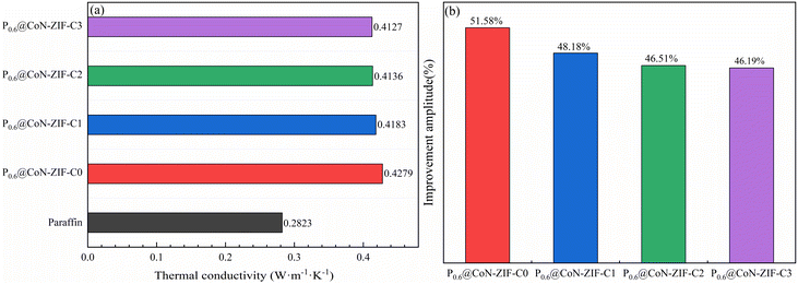 | ||
| Fig. 6 Thermal conductivity and thermal conductivity improvement of composite PCMs (a) thermal conductivity (b) thermal conductivity improvement. | ||
The thermal conductivity improvement amplitude of composite PCMs was listed in Fig. 6b. It is easy to see that the thermal conductivity of the sample with 60% paraffin loading and without acid washing improved to 0.4279 W m−1 K−1, which is up to 51.58% improvement in thermal conductivity compared to 0.2823 W m−1 K−1 of paraffin itself. As the pickling time of the carrier material increases from 1–3 days, the thermal conductivity had a minimal decrease but still had a thermal conductivity improvement of 46.19% to 48.18%. This phenomenon may be because while the pickling process washes away excess impurities, it removes large particles of cobalt monomers, producing a tiny reduction in thermal conductivity.
Collectively, the ZIF-67 high-temperature-derived cobalt/nitrogen carbon nanomaterials had excellent thermal conductivity, constructed efficient heat transfer channels for paraffin core materials, and substantially improved the thermal conductivity of composite PCMs.
3.6. Thermal storage performance of composite PCMs
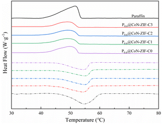
Fig. 7 shows the DSC curve of P0.6@CoN-ZIF-Cx. From the figure, it could be seen that the DSC curve of P0.6@CoN-ZIF-Cx was similar to that of paraffin, and there was only one significant central peak in the melting/solidification process, which indicates that the heat absorption/exothermic process of P0.6@CoN-ZIF-Cx is only the phase change process of paraffin.52The thermal property parameters of paraffin and composite PCMs were listed in Table 3. It could be seen that the enthalpy of melting and enthalpy of crystallization for paraffin were 133.84 J g−1 and 135.93 J g−1, respectively, which was the source of heat storage/exotherm for composite PCMs. According to the mass fraction of paraffin loaded, the theoretical melting enthalpy and crystallization enthalpy of P0.6@CoN-ZIF-Cx are 80.30 J g−1 and 81.56 J g−1, respectively. However, it could be seen from Table 3 that the actual melting/crystallization enthalpy of P0.6@CoN-ZIF-Cx was lower than the theoretical value, indicating that the phase transition process of paraffin was limited by the carrier material CoN-ZIF-Cx, which may be attributed to the strong hydrogen bonding between the nitrogen-doped pore structure and the paraffin molecules, limiting the paraffin molecules in the adhesive part to undergo the phase transition, thus leading to a lower enthalpy of phase transition.
| Sample | Melting process | Crystallization process | ||
|---|---|---|---|---|
| ΔHm (J g−1) | Tm (°C) | ΔHc (J g−1) | Tc (°C) | |
| Paraffin | 133.84 | 54.82 | 135.93 | 51.61 |
| P0.6@CoN-ZIF-C0 | 78.08 | 55.90 | 76.76 | 52.94 |
| P0.6@CoN-ZIF-C1 | 64.56 | 55.64 | 62.58 | 51.69 |
| P0.6@CoN-ZIF-C2 | 66.85 | 55.68 | 64.08 | 51.70 |
| P0.6@CoN-ZIF-C3 | 71.03 | 55.58 | 68.81 | 51.97 |
For the samples before and after pickling, the melting/crystallization enthalpy of P0.6@CoN-ZIF-C0 was much higher than that of P0.6@CoN-ZIF-C1, P0.6@CoN-ZIF-C2, and P0.6@CoN-ZIF-C3, which may be caused by the leakage of a large amount of paraffin in this sample. For samples pickled for 1–3 days, the melting/crystallization enthalpies of the composite PCMs increased gradually with increasing pickling time, and P0.6@CoN-ZIF-C3 possessed 71.03 J g−1 and 68.81 J g−1 of melting enthalpies and crystallization enthalpies. Chun et al.53 Used oil palm shell to prepare carbon based materials as paraffin carrier, and developed composite phase change materials with stable shape. The paraffin load was 31%, the melting and crystallization temperatures of the composites were 29.2 °C and 31.6 °C, and the melting and crystallization enthalpies were 57.3 J g−1 and 57.2 J g−1. At the same time, they showed stable phase change temperature and good thermal cycle stability. Li et al.54 Used MOF-5 skeleton material containing Zn metal to obtain MOF-5 derived porous carbon material and ZnO at high temperature as the carrier to obtain paraffin/MOF-5-PC/ZnO composite phase change material, which has an enthalpy value of 84.96 J g−1, and still maintained at 84.83 J g−1 before and after 50 thermal cycles, proving that the material has thermal cycle stability and has the same trend as this experiment.
The study showed that ZIF-67 derived carbon material can be used as a good carrier to store paraffin, and the adsorption force of its micropores on the phase change material could maintain the stability of the composite. However, a large number of micropores will produce a nano-constraining effect. Mass transfer resistance in the phase change crystallization process was not conducive to the release of latent heat.55 After acid pickling, A washed away excess impurities and large particles of cobalt monomers with a broader pore size, providing a broader phase change space for paraffin molecules and effectively improving the heat storage efficiency.
3.7. Shape setting ability of composite PCMs
The shaping ability of sample P0.6@CoN-ZIF-Cx was measured through the leakage experiment, and the leakage rate (ε) was used as the evaluation index, where the following formula can calculate ε:where: m1 and m2 are the sample masses before and after heating, g.
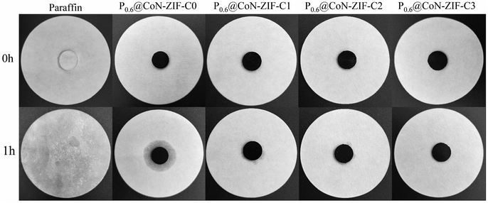
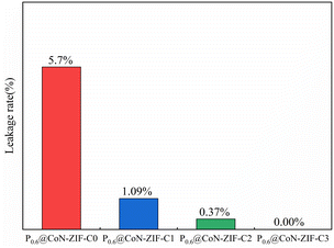
Fig. 8 illustrated the morphological images of the composite PCMs material before and after heating, and Fig. 8 shows the variation of leakage rate for different composite PCMs. The figure shows that the single paraffin completely melted to the liquid state after heating. At the same time, the Px@CoN-ZIF-Cx composite material could maintain the original shape unchanged after heating, indicating that the CoN-ZIF-Cx carrier material could significantly improve the paraffin setting ability. This phenomenon was attributed to the interfacial interaction between the graded pore structure of the CoN-ZIF-Cx carrier material and the nitrogen-doped pore walls, thus limiting the leakage of paraffin molecules.
The area of the shaded area enables further determination of the effect of different pickling times on the ability to set the shape of the material. The P0.6@CoN-ZIF-C0 sample has the largest shaded area, indicating the most severe leakage, with a leakage rate of 5.7%. With the increase in the pickling time of carrier material, the shadow area of the Px@CoN-ZIF-Cx composite gradually decreases. The leakage rates of P0.6@CoN-ZIF-C1 and P0.6@CoN-ZIF-C2 samples after pickling for 1 to 2 days are 1.09% and 0.37%. When the pickling time was extended to three days, the P0.6@CoN-ZIF-C3 sample did not leak.
According to the analysis, this phenomenon may be attributed to the small pore size, pore volume, and specific surface area of CoN-ZIF-C0, which cannot absorb all paraffin molecules, resulting in leakage. After pickling, the CoN-ZIF-Cx carrier material washed away the excess impurities, the metal ions and large particles of cobalt were screened out, the pore size and specific surface area increased, and the hierarchical pore structure was more conducive to the entry of paraffin molecules into the pore structure, providing sufficient physical space to limit the paraffin leakage together with the gross management, surface tension, and hydrogen bonding.56 Under multiple factors, Px@CoN-ZIF-Cx had built an excellent shape-setting ability (Fig. 9).
3.8. Thermal cycle stability of composite PCMs
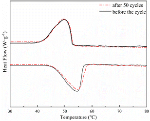
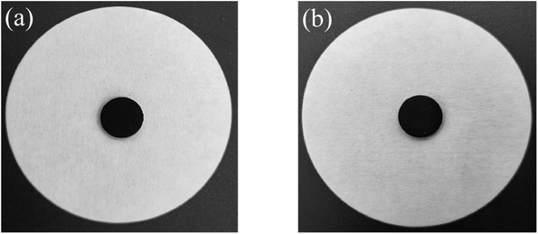
Considering the thermal properties and shape setting ability of multiple samples, CoN-ZIF-C3 was selected as the best carrier material after pickling for three days, and the thermal cycle experiment of P0.6@CoN-ZIF-C3 sample was carried out 50 times to detect and analyze its stability. Fig. 10 and 11 shows the DSC and chemical structure analyses of P0.6@CoN-ZIF-C3 after 50 thermal cycles. Fig. 12 shows the morphology change of P0.6@CoN-ZIF-C3 after 50 thermal cycles. It could be observed from Fig. 10 that the DSC curves of P0.6@CoN-ZIF-C3 did not change significantly after 50 thermal cycles. The melting/crystallization enthalpies changed from 71.03 J g−1 and 68.81 J g−1 to 70.22 J g−1 and 68.05 J g−1, and the melting/crystallization enthalpies decreased by 0.81 J g−1 and 0.76 J g−1, respectively, with a change of less than 1.2%. It could be seen from Fig. 11 that the XRD and FTIR spectra of P0.6@CoN-ZIF-C3 had not changed significantly before and after 50 thermal cycles, indicating that the phase composition had not changed. It could be seen from Fig. 12 that the morphology of P0.6@CoN-ZIF-C3 has no change before and after 50 thermal cycles, and no collapse and melting phenomena are found. In conclusion, P0.6@CoN-ZIF-C3 had good thermal cycle stability.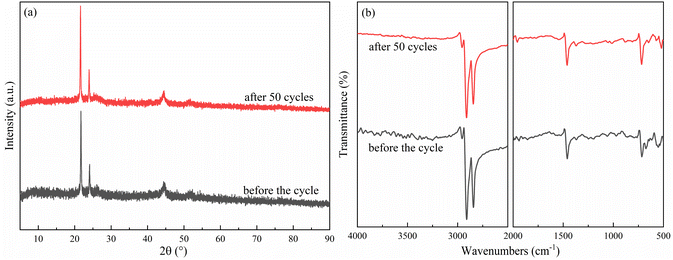 | ||
| Fig. 11 Chemical structure analysis of the P0.6@CoN-ZIF-C3 before and after 50 thermal cycles (a) XRD pattern (b) FTIR pattern. | ||
4. Conclusions
To solve the problems of easy leakage and low thermal conductivity of paraffin in the process of phase transition, the cobalt/nitrogen-doped ZIF-67 derived carbon material was used as the carrier, and the composite PCMs with improved thermal conductivity were constructed with paraffin core material after acid pickling for different times, XRD, FTIR, SEM, and BET were used to characterize the composite PCMs. The thermal properties of the composite PCMs were investigated by DSC, TPS, and other similar methods, and the main conclusions were as follows:(1) The characterization results prove that the compounding of paraffin and carrier material involves only physical processes without chemical change. Characterization, a thermal performance test, and an anti-leakage test taken together, CoN-ZIF-Cx carrier material could load paraffin up to 60%, effectively solving the problem of easy leakage during the paraffin phase change.
(2) The cobalt/nitrogen-doped carbon-based carrier had a graded pore structure that provided sufficient capillary management and surface tension to limit paraffin leakage together with hydrogen bonding; it could offer enough physical space for the phase transition of the paraffin core so that the composite material still had excellent shaping ability, thermal storage capacity, and thermal cycling stability.
(3) The thermal conductivity of sample P0.6@CoN-ZIF-C3 was 0.4127 W m−1 K−1, which was 46.19% higher than that of the pure paraffin core of 0.2823 W m−1 K−1, and the heat transfer performance was greatly improved. At the same time, the composite PCMs still possessed excellent heat storage performance, with enthalpy of melting and enthalpy of crystallization of 71.03 J g−1 and 68.81 J g−1, respectively, and still had favourable heat storage capacity after 50 repeated thermal cycles.
Author contributions
Conceptualization, Y. L. and Y. G.; methodology, Y. G., G. T. and Y. L.; validation, X. C. and Z. Z.; formal analysis, Y. T. and Y. G.; investigation, Y. L.; resources, Y. G., X. R., and B. C.; data curation, Y. L.; writing—original draft preparation, Y. L. and Y. G.; writing—review and editing, G. T., X. Z.; supervision, Y. G., Z. Z., and B. C.; project administration, Y. G.; funding acquisition, Y. G., Z. Z. and B. C. All authors have read and agreed to the published version of the manuscript.Conflicts of interest
There are no conflicts to declare.Acknowledgements
China Postdoctoral Science Foundation (2020M671983); Postdoctoral Innovation Project of Shandong Province (202103077); China Scholarship Council (202008370134); Shandong Province Housing and Urban-Rural Construction Science and Technology Project (2022-K7-11, 2021-K8-10, 2020-K2-10); National Natural Science Foundation of China (51976111); Doctoral Fund of Shandong Jianzhu University (X18069Z); The Plan of Guidance and Cultivation for Young Innovative Talents of Shandong Provincial Colleges and Universities.References
- Y. Q. Li, Y. M. Chen, X. B. Huang, S. H. Jiang and G. Wang, Chem. Eng. J., 2021, 415 CAS.
- R. Li, W. Zhang and K. Zhou, Adv. Mater., 2018, 30, 1705512 CrossRef PubMed.
- X. Chen, X. Y. Kong, S. Y. Wang, Y. S. Zhang, W. L. Zhong, A. G. Lu, W. Y. Xu, L. Z. Liu and Y. X. Liu, J. Energy Storage, 2021, 40 CAS.
- S. Shoeibi, H. Kargarsharifabad, S. Mirjalily, M. Sadi and A. Arabkoohsar, J. Energy Storage, 2022, 50 Search PubMed.
- F. Hassan, F. Jamil, A. Hussain, H. M. Ali, M. M. Janjua, S. Khushnood, M. Farhan, K. Altaf, Z. Said and C. H. Li, Sustain. Energy Technol. Assess., 2022, 49, 101646 Search PubMed.
- W. X. Wu, W. Wu and S. F. Wang, Appl. Energy, 2019, 236, 10–21 CrossRef CAS.
- J. J. Wang, X. B. Huang, H. Y. Gao, A. Li and C. Wang, Chem. Eng. J., 2018, 350, 164–172 CrossRef CAS.
- H. Selvnes, Y. Allouche, R. I. Manescu and A. Hafner, Therm. Sci. Eng. Prog., 2021, 22, 100807 CrossRef.
- T. T. Shi, X. G. Zhang, J. X. Qiao, X. W. Wu, G. Chen, G. Q. Leng, F. K. Lin, X. Min and Z. H. Huang, Polymer, 2021, 212 Search PubMed.
- X. Y. Zhao, D. Q. Zou and S. Wang, Chem. Eng. J., 2022, 431 Search PubMed.
- S. Zhang, D. L. Feng, L. Shi, L. Wang, Y. G. Jin, L. M. Tian, Z. Y. Li, G. Y. Wang, L. Zhao and Y. Y. Yan, Renew. Sust. Energ. Rev., 2021, 135 Search PubMed.
- H. Nazir, M. Batool, F. Osorio, M. Isaza-Ruiz, X. H. Xu, K. Vignarooban, P. Phelan, I. Inamuddin and A. M. Kannan, Int. J. Heat Mass Tran., 2019, 129, 491–523 CrossRef CAS.
- Q. Q. Huang, X. X. Li, G. Q. Zhang, J. Deng and C. H. Wang, Appl. Therm. Eng., 2021, 183 Search PubMed.
- D. G. Atinafu, B. Y. Yun, S. Wi, S. J. Chang and S. Kim, J. Energy Storage, 2023, 60 Search PubMed.
- X. L. Ma, Y. F. Zhang, Z. H. Han, N. B. Zang and Z. J. Liu, Energy, 2023, 268 Search PubMed.
- H. Mehling, M. Brutting and T. Haussmann, J. Energy Storage, 2022, 51 Search PubMed.
- D. K. Mishra, C. Bhowmik, S. Bhowmik and K. M. Pandey, Environ. Sci. Pollut. Res., 2022, 29, 43556–43587 CrossRef CAS PubMed.
- T. Hu, S. Chang, H. Wu, L. Li and W. Yuan, Sol. Energy Mater. Sol. Cells, 2021, 232, 111339 CrossRef CAS.
- S. Bahrami, M. Mizani, M. Honarvar and M. A. Noghabi, Iran. Polym. J., 2017, 26, 885–893 CrossRef CAS.
- L. Y. Wang, Z. J. Liu, Q. G. Guo, H. Q. Wang, X. L. Wang, X. Z. Dong, X. D. Tian and X. H. Guo, Coatings, 2022, 12 Search PubMed.
- M. Wang, P. Li and F. Q. Yu, Renewable Energy, 2021, 172, 599–605 CrossRef CAS.
- D. G. Atinafu, W. J. Dong, C. M. Hou, R. S. Andriamitantsoa, J. J. Wang, X. B. Huang, H. Y. Gao and G. Wang, Mater. Today Energy, 2019, 12, 239–249 CrossRef.
- P. C. Rao and S. Mandal, Chem.–Asian J., 2019, 14, 4087–4102 CrossRef CAS PubMed.
- C. Liu, J. Wang, J. J. Wan and C. Z. Yu, Coord. Chem. Rev., 2021, 432 CAS.
- G. H. Zhong, D. X. Liu and J. Y. Zhang, J. Mater. Chem. A, 2018, 6, 1887–1899 RSC.
- D. G. Prajapati and B. Kandasubramanian, Ind. Eng. Chem. Res., 2019, 58, 10652–10677 CrossRef CAS.
- W. D. Fan, X. R. Zhang, Z. X. Kang, X. P. Liu and D. F. Sun, Coord. Chem. Rev., 2021, 443 Search PubMed.
- X. L. Li, X. X. Sheng, Y. Q. Guo, X. Lu, H. Wu, Y. Chen, L. Zhang and J. W. Gu, J. Mater. Sci. Technol., 2021, 86, 171–179 CrossRef CAS.
- X. Chen, P. Cheng, Z. D. Tang, X. L. Xu, H. Y. Gao and G. Wang, Adv. Sci., 2021, 8, 2001274 CrossRef CAS PubMed.
- H. Li, F. S. Liu, X. L. Ma, P. Cui, M. Guo, Y. Li, Y. Gao, S. J. Zhou and M. Z. Yu, Renewable Energy, 2020, 149, 816–827 CrossRef CAS.
- J. N. Ding, Y. J. Tang, S. S. Zheng, S. T. Zhang, H. G. Xue, Q. Q. Kong and H. Pang, Nano Res., 2022, 15, 6793–6818 CrossRef CAS.
- S. F. Wu, T. Yan, Z. H. Kuai and W. G. Pan, Energy Storage Mater., 2020, 25, 251–295 CrossRef.
- H. N. Tran, N. B. Nguyen, N. H. Ly, S. W. Joo and Y. Vasseghian, Environ. Pollut., 2023, 317 Search PubMed.
- X. Chen, H. Y. Gao, L. W. Xing, W. J. Dong, A. Li, P. Chengh, P. P. Liu and G. Wang, Energy Storage Mater., 2019, 18, 280–288 CrossRef.
- K. Chen, C. M. Wang, T. J. Wang, Z. M. Zhu, R. T. Ma and H. Jiang, J. Polym. Res., 2020, 27, 199 CrossRef CAS.
- R. Bardestani, G. S. Patience and S. Kaliaguine, Can. J. Chem. Eng., 2019, 97, 2781–2791 CrossRef CAS.
- Z. Q. Xu, J. X. Li, X. R. Li, Z. Chen, C. Chen, S. Shah and M. Q. Wu, Appl. Surf. Sci., 2021, 565 Search PubMed.
- T. T. Qian, J. H. Li, X. Min and B. Fan, ACS Sustain. Chem. Eng., 2018, 6, 897–908 CrossRef CAS.
- R. Sattar, T. Ishaq, A. Afzal, R. Mukhtar and A. Naz, Energy Sources, Part A Recovery, Util. Environ. Eff., 2022, 44, 2133–2152 CrossRef CAS.
- Z. P. Yu, Y. H. Feng, D. L. Feng and X. X. Zhang, Microporous Mesoporous Mater., 2021, 312 Search PubMed.
- H. S. Jadhav, H. A. Bandal, S. Ramakrishna and H. Kim, Adv. Mater., 2022, 34, 2107072 CrossRef CAS PubMed.
- Y. N. Guo, J. Tang, R. R. Salunkhe, Z. A. Alothman, M. Hossain, V. Malgras and Y. Yamauchi, Bull. Chem. Soc. Jpn., 2017, 90, 939–942 CrossRef CAS.
- R. T. Yang, D. Li, S. L. Salazar, Z. H. Rao, M. Arici and W. Wei, Sol. Energy Mater. Sol. Cells, 2021, 219 Search PubMed.
- C. X. Duan, Y. Yu and H. Hu, Green Energy Environ., 2022, 7, 3–15 CrossRef CAS.
- D. G. Atinafu, S. J. Chang, K. H. Kim, W. J. Dong and S. Kim, Chem. Eng. J., 2020, 389 Search PubMed.
- S. M. Lashgari, H. Yari, M. Mahdavian, B. Ramezanzadeh, G. Bahlakeh and M. Ramezanzadeh, J. Hazard. Mater., 2021, 404 Search PubMed.
- L. P. Bi, G. C. Long, Z. Tang, M. L. Guo, X. H. Zeng and Y. J. Xie, Constr. Build. Mater., 2021, 310 Search PubMed.
- D. Li, X. M. Cheng, Y. Y. Li, H. Y. Zou, G. M. Yu, G. Li and Y. Huang, Sol. Energy, 2018, 171, 142–149 CrossRef CAS.
- Z. P. Yu, D. L. Feng, Y. H. Feng and X. X. Zhang, Compos. Part A Appl. Sci. Manuf., 2022, 152 Search PubMed.
- X. B. Huang, X. Chen, A. Li, D. Atinafu, H. Y. Gao, W. J. Dong and G. Wang, Chem. Eng. J., 2019, 356, 641–661 CrossRef CAS.
- B. L. Chen, G. P. Ma, Y. Q. Zhu and Y. D. Xia, Sci. Rep., 2017, 7, 5266 CrossRef PubMed.
- Y. W. Hu, X. D. Song, Q. L. Zheng, J. N. Wang and J. F. Pei, RSC Adv., 2019, 9, 9962–9967 RSC.
- C. O. Chin, X. Yang, S. C. Paul, S. Susilawati, L. S. Wong and S. Y. Kong, J. Clean Prod., 2020, 261, 121227 CrossRef CAS.
- A. Li, Y. Wan, Y. Gao, Z. Tang, J. Xu, M. Huang, Y. Li, X. Zhang and X. Chen, Mater. Today Nano, 2022, 20, 100277 CrossRef CAS.
- X. Tong, N. Q. Li, M. Zeng and Q. W. Wang, Renew. Sust. Energ. Rev., 2019, 108, 398–422 CrossRef CAS.
- D. G. Atinafu, B. Y. Yun, S. Wi, Y. J. Kang and S. Kim, Environ. Res., 2021, 195 Search PubMed.
| This journal is © The Royal Society of Chemistry 2023 |


