
 Open Access Article
 This Open Access Article is licensed under a Creative Commons Attribution-Non Commercial 3.0 Unported Licence
Dielectric and energy storage properties of surface-modified BaTi0.89Sn0.11O3@polydopamine nanoparticles embedded in a PVDF-HFP matrix
Marwa Zahid a,
Salma Touiliab,
M'barek Amjouda,
Daoud Mezzaneab,
Mohamed Gounéc,
Hana Uršičd,
Matej Šadld,
Youssef Elamraouie,
Khalid Hoummadaf,
Zdravko Kutnjak*d and
Mimoun El Marssib
a,
Salma Touiliab,
M'barek Amjouda,
Daoud Mezzaneab,
Mohamed Gounéc,
Hana Uršičd,
Matej Šadld,
Youssef Elamraouie,
Khalid Hoummadaf,
Zdravko Kutnjak*d and
Mimoun El Marssib
aIMED-Lab, Cadi-Ayyad University, FST, Marrakech, 40000, Morocco. E-mail: marwa.zahid@ced.uca.ma
bLPMC, University of Picardie Jules Verne, Amiens, 80039, France
cICMCB, University of Bordeaux, Pessac, 33600, France
dJožef Stefan Institute, Jamova Cesta 39, Ljubljana, 1000, Slovenia
eLaMCScI, Faculty of Science, Mohammed V University, BP 1014, Rabat, Morocco
fIM2NP, Aix Marseille University, Marseille, 13397, France
First published on 1st September 2023
Abstract
In the most recent electronic and electric sectors, ceramic–polymer nanocomposites with high dielectric permittivity and energy density are gaining popularity. However, the main obstacle to improving the energy density in flexible nanocomposites, besides the size and morphology of the ceramic filler, is the low interfacial compatibility between the ceramic and the polymer. This paper presents an alternative solution to improve the dielectric permittivity and energy storage properties for electronic applications. Here, the poly(vinylidene fluoride-hexafluoropropylene) (PVDF-HFP) matrix is filled with surface-modified BaTi0.89Sn0.11O3/polydopamine nanoparticles (BTS11) nanoparticles, which is known for exhibiting multiphase transitions and reaching a maximum dielectric permittivity at room temperature. BTS11 nanoparticles were synthesized by a sol–gel/hydrothermal method at 180 °C and then functionalized by polydopamine (PDA). As a result, the nanocomposites exhibit dielectric permittivity (εr) of 46 and a low loss tangent (tan![[thin space (1/6-em)]](https://www.rsc.org/images/entities/char_2009.gif) δ) of 0.017 at 1 kHz at a relatively low weight fraction of 20 wt% of BTS11@PDA. This is approximately 5 times higher than the pure PVDF-HFP polymer and advantageous for energy storage density in nanocomposites. The recovered energy storage for our composites reaches 134 mJ cm−3 at an electric field of 450 kV cm−1 with a high efficiency of 73%. Incorporating PDA-modified BTS11 particles into the PVDF-HFP matrix demonstrates highly piezo-active regions associated with BTS11 particles, significantly enhancing functional properties in the polymer nanocomposites.
δ) of 0.017 at 1 kHz at a relatively low weight fraction of 20 wt% of BTS11@PDA. This is approximately 5 times higher than the pure PVDF-HFP polymer and advantageous for energy storage density in nanocomposites. The recovered energy storage for our composites reaches 134 mJ cm−3 at an electric field of 450 kV cm−1 with a high efficiency of 73%. Incorporating PDA-modified BTS11 particles into the PVDF-HFP matrix demonstrates highly piezo-active regions associated with BTS11 particles, significantly enhancing functional properties in the polymer nanocomposites.
1. Introduction
The ecological and energy transition must address the need for a growing and more energy-intensive economy while respecting environmental constraints and ecological considerations. In this context, there is currently great interest in developing innovative environmental technologies for energy storage and recovery. Furthermore, with the ever-increasing trend of modern electronics integration, miniaturization, and multi-functionalization, nanocomposite materials with high dielectric permittivity may find more widespread use in capacitors, field effect transistors, memory, and energy storage devices.1–7In this particular case, power electronics applications require relatively light passive components that occupy the smallest volume possible, along with high dielectric permittivity, high dielectric breakdown strength, and good machinability. However, optimizing all of this simultaneously is extremely challenging. In general, combining piezoelectric ceramic and a polymer is a compelling solution that results in nanocomposite materials that benefit from the ferroelectric filler's high dielectric permittivity and the polymer's high dielectric breakdown strength.8
Lead-based perovskite materials have been considered the best candidates for energy storage, energy harvesting, piezoelectric photodegradation, and hydrogen production due to their astounding dielectric properties.9–13 Due to their excellent dielectric properties, lead-based ceramics such as PbZrxTi1−xO3 (PZT) and (1 − x)Pb(Mg1/3Nb2/3)O3−xPbTiO3 (PMN-PT) systems dominate the piezoelectric device market today.13–17 On the other hand, barium titanate and its derivates, such as BaxSr(1−x)TiO3 (BST), BaxCa(1−x)Zr(1−y)TiyO3 (BCZT), and BaxCa(1−x)Ti(1−y)SnyO3 (BCTS) have been wildly used in the energy storage nanocomposites as a replacement for the lead-based ceramics, due to their ecological nature and their acceptable dielectric, ferroelectric and piezoelectric properties.18–23 In our previous research, we investigated the lead-free BaTi0.89Sn0.11O3 (BTS11), which demonstrated enhanced dielectric properties and energy storage at temperatures close to room temperature due to the multiphase phenomenon.10,24 At room temperature, enhanced dielectric and ferroelectric properties could be advantageous for ceramic/polymer composites, providing an effective piezoelectric material for flexible energy storage and energy harvesting systems.
PVDF-based polymers are widely used in composites because of their dielectric performance (εr ∼10), simple process, good biocompatibility, stable piezoelectric power output, and other advantages.25,26 Sadhu et al. fabricated a 15 vol%-BCZT/PVDF-HFP composite, which exhibited an εr ∼19 at 10 kHz, with an energy storage density of 7.64 J cm−3.23 Li et al. obtained an εr of ∼22 at 1 kHz for5 vol%-BaTiO3 (BT) nanofiber/PVDF-HFP composite and an energy storage density of 8.55 J cm−3 at 300 MV m−1.27 Kumar et al. fabricated the composite samples by synthesizing a BZT-BCT (0.5BZT-0.5BCT) ceramic pellet, sintering it at 1450 °C, grinding it, and then hydroxylating it with an H2O2 solution and incorporating 15 wt% of the nanopowder into a PVDF-HFP matrix. This composite sample exhibited an εr of 34.3 Moreover, the εr of a BST/PVDF composite at 1 kHz increases from ∼10 for pure PVDF to 37 for the composite containing 25 vol% of BST.18 In contrast, Mei et al. observed a monotonic increase in εr from 14 for pure PVDF-HFP to 42 for 40 vol%-BST/PVDF-HFP composite at 100 Hz, with a maximum Udischarge of 3.79 J cm−3 at 2100 kV cm−1 with a 20 vol% BST content.28
In this respect, to further improve the dielectric and energy storage properties in the flexible piezo-composites at a low filler percentage, PDA surface-modified BTS11 nanoparticles were embedded into the PVDF-HFP matrix. First, the BTS11 nanopowders were elaborated at low temperatures using a sol–gel/hydrothermal method. Then the surface of the BTS11 was hydroxylated with H2O2 and finally chemically modified with the PDA to improve the interfacial interaction between the fillers and the PVDF-HFP matrix.
2. Experimental details
2.1. Preparation of the BTS11
Pure crystalline BaTi0.89Sn0.11O3 nanopowders were obtained using previously reported sol–gel/hydrothermal method at 180 °C.10 The first step in the surface modification process was hydroxylation. For this, 1 g of the BTS11 was sonicated for 30 min and then refluxed in 100 ml H2O2 for 4 h at 106 °C. The hydroxylated nanopowder was washed with ethanol and distilled water several times before drying overnight at 80 °C. Next, BTS11 nanoparticles were added to a 0.01 M dopamine hydrochloride ((HO)2C6H3CH2CH2NH2·HCl) aqueous solution and stirred on a magnetic stirrer at 60 °C for 24 h. Finally, the black suspension BTS11@PDA was again washed with distilled water and ethanol several times and dried at 80 °C for 12 h.2.2. Fabrication of the BTS11/PVDF-HFP nano-composites
First, an appropriate amount of poly(vinylidene fluoride-co-hexafluoropropylene) (PVDF-HFP) pellets were dissolved in dimethylformamide (DMF) and stirred for 24 h with a magnetic stirrer. Next, an adequate quantity of BTS11@PDA nanopowder was mixed with a DMF solution, sonicated for 30 min, and stirred for an additional hour. The BTS11/DMF slurry was dropped into the PVDF-HFP solution and ultrasonicated for 15 min. Finally, the mixture was poured into a Teflon mold and dried for 12 h in a vacuum oven at 60 °C to remove the solvent. The resulting films were then hot pressed for 10 min at 200 °C. Four different compositions were synthesized. All reactants are analytical-grade and used without any further purification. A schematic presentation of the fabrication process is shown in Fig. 1.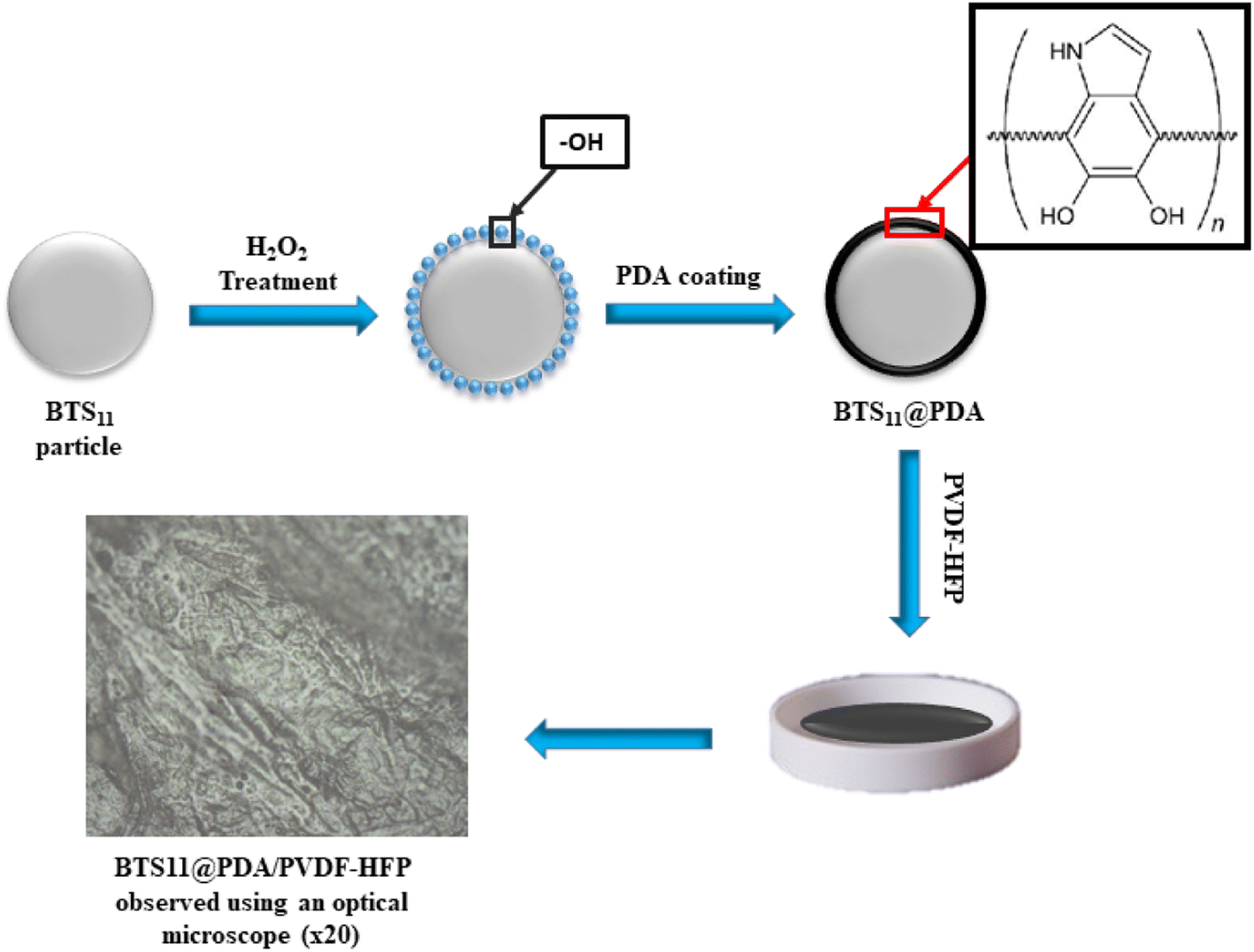 | ||
| Fig. 1 Schematic diagram of the process for synthesizing BTS11@PDA/PVDF-HFP nanocomposites. | ||
2.3. Characterization
X-ray diffraction (XRD) measurements were carried out using an X-ray diffractometer brand ‘‘RIGAKU”. X-rays were produced from a CuKa radiation source, having a wavelength equal to 1.54056 Å. X-ray diffraction spectra were recorded at room temperature in the range of 2Θ between 20° and 80° with angle steps of 0.02°. A 5° per min scanning speed was employed to perform simple phase identification. Moreover, to have a quick insight into the purity of our samples, the Fourier-transform infrared spectroscopy (FTIR) measurements were carried out using a Bruker Vertex 70 spectrophotometer in transmission mode, 0.001 g of the powders were dispersed in 0.099 g of KBr matrix and analyzed in the frequency range 400–4000 cm−1. The polarization–electric field (P–E) hysteresis loops were performed by CPE1701, PloyK, USA, with a high-voltage power supply (Trek 609-6, USA).The microstructure of the samples was analyzed using a field emission scanning electron microscope (FE-SEM, JSM-7600F, JEOL, Japan). To prevent charging during analysis, a few nanometers thick carbon layer was deposited on the samples using a Precision Etching and Coating System (PECS 682, Gatan, USA). Piezo-response force microscopy (PFM) was performed on the surface of the prepared composite samples. An atomic force microscope (AFM; Jupiter XR Asylum Research, Oxford Instruments, CA, USA) and platinum-coated silicon tips with a radius of curvature ∼10 nm (OMCL-AC240TM-R3, Olympus, Japan) were used for the analysis. The images were scanned in dual AC resonance-tracking mode. An electrical voltage of 3 V and a frequency of ∼250 kHz was applied between a conductive AFM tip and the silver paste that served as the bottom electrode. After the PFM scans, the PFM phase hysteresis loops were measured in switching spectroscopy mode using the pulsed DC step signal and the superimposed AC drive signal, as described in ref. 29. The waveform parameters were as follows: the sequence of increasing steps of the DC electric field was driven at 20 Hz and a maximum amplitude of 40 or 50 V; the frequency of the triangular envelope was 0.99 Hz; a superimposed sinusoidal AC signal with an amplitude of 2 V and a frequency of ∼310 kHz was used. Three cycles were measured in an off-electric-field mode.
3. Results and discussion
The XRD pattern of the as-prepared BTS11 powder is displayed in Fig. 2. According to XRD analysis, the powder exhibits a pure perovskite structure devoid of any secondary phases. The BTS11 multiphase was previously demonstrated in two of our previous published papers,10,24 and it was also reported in the literature.30,31 Therefore, the as-prepared powder (BTS11), the hydroxylated powder (OH-BTS11), and then the PDA-coated BTS11 powder (BTS11@PDA) were all subjected to FTIR analysis to show whether the dopamine successfully bonded to the surface of the BTS11, as demonstrated in Fig. 3. Particularly for the powders synthesized by the hydrothermal method, hydroxyl groups have reportedly been identified on the surface of barium titanate-based materials.32,33 However, the (–OH) amount needed to achieve acceptable compatibility with the polymer matrix is still insufficient and requires surface modification.10 Therefore, the surface of BTS11 nanopowders was first hydroxylated with H2O2 and then coated with a PDA layer to increase the chemical interactions between BTS11 nanoparticles and the PVDF-HFP matrix.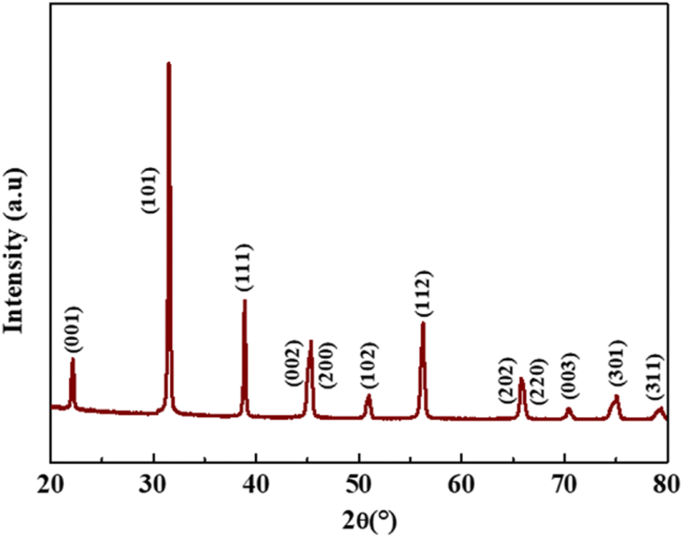 | ||
| Fig. 2 XRD pattern of the as-prepared BTS11 powder. | ||
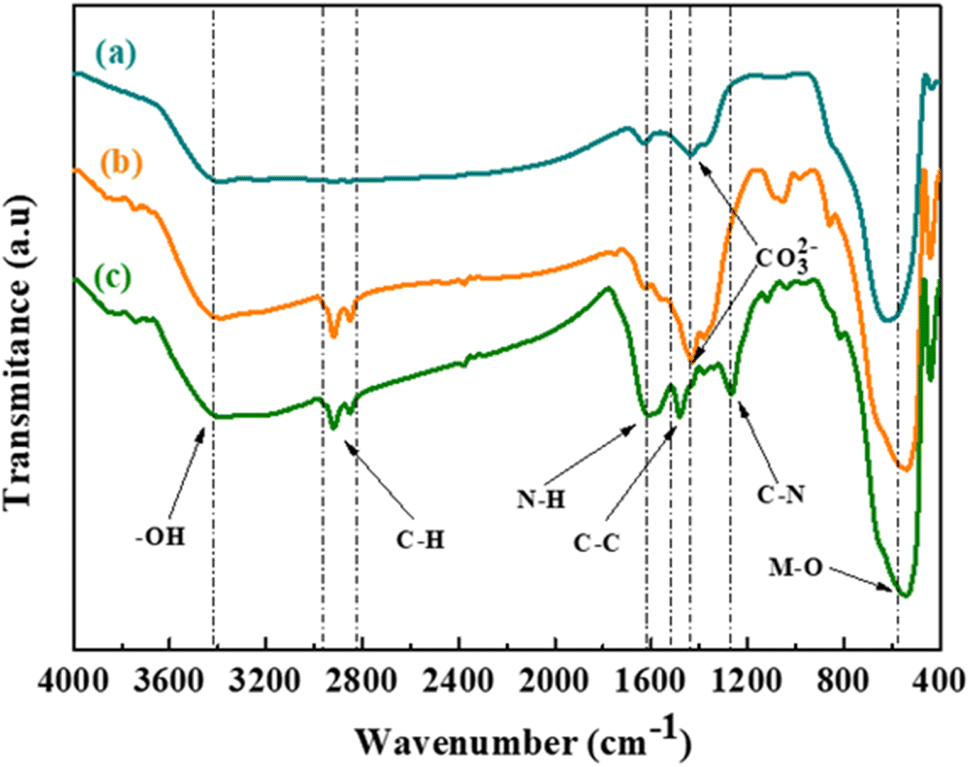 | ||
| Fig. 3 FTIR spectra of (a) the as-prepared BTS11 powder, (b) the hydroxylated BTS11 powder, and (c) BTS11@PDA powder. | ||
The band at 3445 cm−1, corresponding to the stretching mode of the (–OH), is observed in the FTIR spectrum of as-prepared BTS11 powder (Fig. 3a). It grew wider in the spectra of hydroxylated powder and powder coated with PDA (Fig. 3b and c, respectively), suggesting that the surface hydroxylation was accomplished.34,35 The increasing intensity of the –M–O absorption band, centered between 500 and 650 cm−1, indicates that the surface powder's functionalization was effective. There is noteworthy observation in the vibrations of the M–O functional groups within the treated BTS11 samples compared to the pure BTS11 material. Specifically, following the treatment with hydrogen peroxide, a distinct shift of the M–O bands towards lower wavenumbers was observed, indicating a decrease in the stretching vibration frequency of the M–O bonds. This intriguing phenomenon can be elucidated by considering the effective interaction occurring between the M–O bands and the –H and –OH groups present in the hydrogen peroxide (H2O2) and the dopamine (C8H11NO2) solutions during the treatment process. As these reactants are introduced to the BTS material, the –H and –OH groups interact with the M-O bonds, causing notable alterations in the electron cloud density surrounding these bonds. Consequently, the M–O bonds experience a spreading effect, leading to a reduction in their rigidity and causing a decrease in the frequency of their stretching vibrations.6 Furthermore, bands at 1260 cm−1, 1480 cm−1, 1620 cm−1 and 1900 cm−1 correspond to the aromatic amine's C–N stretching vibration, aromatic C–C stretching vibration, N–H bending vibration, and finally, the C–H stretching vibration, respectively. The latter indicates that the BTS11 nanoparticles were successfully coated with PDA.36 The peak at 1450 cm−1, assigned to the stretching vibration of CO32−, is significantly weakened when coated with PDA, which could be due to the presence of carbonates due to CO2 adsorption.37,38
Fig. 4a shows the SEM micrograph of the BTS11 nanopowder, while Fig. 4b shows the SEM micrograph of the BTS11@PDA, and Fig. 4c depicts the 20 wt%-BTS11@PDA/PVDF-HFP composites. Dopamine is easily self-polymerized, and the formation of polydopamine has high adherence to the surface of practically all types of oxides. The PDA layer can serve as a foundation for introducing the polymer matrix, allowing the attachment of other molecules onto the nanoparticles' surface. This can also enhance their dispersibility, stability, and compatibility with the PVDF-HFP polymer matrix.
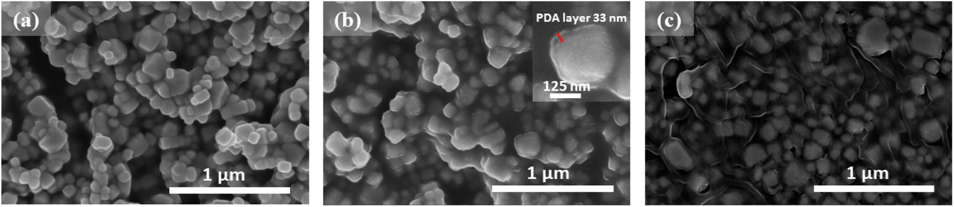 | ||
| Fig. 4 SEM micrographs of the (a) as-prepared BTS11 nanopowder and (b) the PDA functionalized BTS11 (BTS11@PDA) with an inset showing the PDA layer on a BTS11 particle, and (c) 20 wt%-BTS11@PDA/PVDF-HFP nanocomposite. | ||
The PDA coating can also improve the nanoparticles' biocompatibility, adhesion, and chemical stability. The Fig. 4c shows that the BTS11 nanoparticles are uniformly dispersed in the PVDF-HFP matrix. The SEM image of the BTS11's core–shell structure is shown in the inset of Fig. 4b, and the polydopamine shell's thickness is approximately 33 nm.
Fig. 5 illustrates the XRD patterns of the BTS11/PVDF-HFP composites with a different weight percentage of BTS11@PDA in the polymer matrix (2, 8, 14, and 20 wt%). The semi-crystalline nature of the PVDF-HFP is proved by the peaks positioned between 16° and 27° (Fig. 5a). The α-phase diffraction peaks situated at 17.4°, 18°, 19.4° and 22°, may be indexed as α(100), α(020), α(110) and α(020) respectively, while the β-phase is situated at 20° and is attributed to β(110) and β(200).39,40 The diffraction peaks of the BTS11 get more detectable with the filler addition, while the PVDF-HFP diffraction peaks gradually vanish. It is important to note that the crystallinity of the ceramic filler does not change; it just becomes more visible as the filler amount increases.
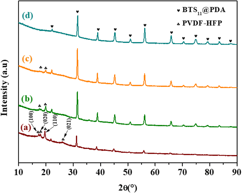 | ||
| Fig. 5 XRD patterns of x wt%-BTS11@PDA/PVDF-HFP composites with different weight percentage (a) x = 2 wt%, (b) x = 8 wt%, (c) x = 14 wt% and (d) x = 20 wt%. | ||
The PFM analysis was performed to evaluate the local piezoelectricity of prepared nanocomposites. PFM is a valuable technique for the determination of the local piezoelectric properties of composites and thick films.29 It is based on measuring the ferroelectric material's local electromechanical response via the converse piezoelectric effect. On surface topography height and deflection images (Fig. 6a and b), the BTS11 particles' filler grains can be clearly distinguished from the polymer matrix. Bright islands in the PFM amplitude image (Fig. 6c) demonstrate the BTS11 particles' strong piezoelectric activity, which is also evident from the contrast in the PFM phase image (Fig. 6d). The local PFM phase and amplitude hysteresis in two distinct areas were also tested using a PFM switching spectroscopic experiment (Fig. 6e–h). The typical ferroelectric/piezoelectric PFM phase hysteresis loops were obtained in both areas. Furthermore, the butterfly-shaped PFM amplitude hysteresis loops demonstrate the clear piezoelectric aspect of BTS11 filler.
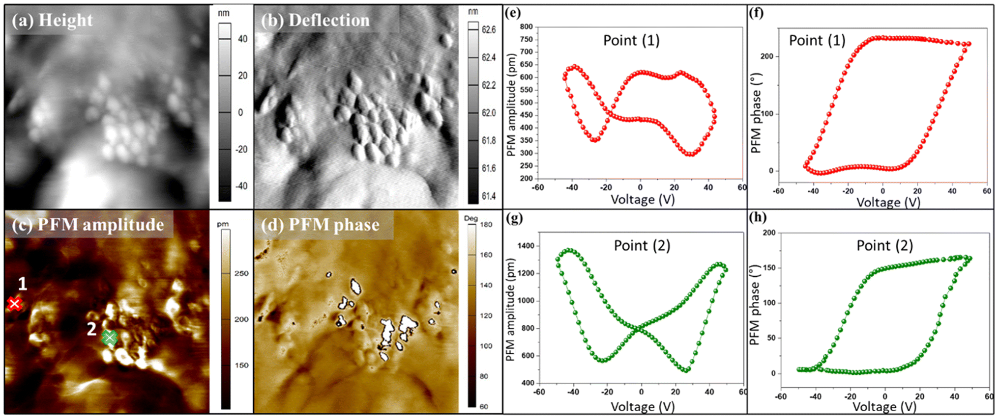 | ||
| Fig. 6 The AFM/PFM analysis of 20 wt%-BTS11@PDA/PVDF-HFP nanocomposites. (a) The AFM topography height, (b) deflection images, (c) PFM out-of-plane amplitude, and (d) phase images. The PFM amplitude (e and g) and phase hysteresis loops (f and h), measured at the spots marked in panel (c) by numbers 1 and 2. Three hysteresis cycles were measured, only the second cycle is shown here. | ||
The study aimed to benefit from the BTS11 filler's multiphase, in which the tetragonal, orthorhombic, rhombohedric, and cubic phases coexist at room temperature, as demonstrated in our previous works.10,24 At room temperature, multiphase coexistence usually leads to enhanced dielectric properties in the lead-free BTS11 ceramic.
Hence, the dielectric properties at room temperature of our nanocomposites were measured and depicted in Fig. 7. As shown in Fig. 7a, εr increased significantly as the BTS11@PDA amount increased. At the same time, it was only slightly dependent on the frequency over the measured range (1 Hz–1 MHz). Notably, at 20 wt%, the dielectric permittivity of nanocomposites reaches 54 at 1 Hz, 46 at 1 kHz, and 42 at 100 kHz, which is about 5 times the dielectric permittivity of the pure PVDF-HFP. As shown in Fig. 7b, the value of tanδ decreased with increasing frequency over the range of 1 Hz−1 kHz owing to the relaxation loss caused by Maxwell–Wagner–Sillars (MWS) interfacial polarization.41,42 The dielectric loss between 103 and 105 Hz remains at a low level of less than 0.015. Above 105 Hz, tanδ sharply increases, which is attributed to α relaxation associated with the glass transition of the pure PVDF polymer.43,44 It should be noted that in the frequency range of 1–10 (ref. 5) Hz, the tanδ value of the 20 wt%-BTS11@PDA/PVDF-HFP composite was the lowest among all prepared composites. A similar shape of the measured curves of tanδ versus frequency was previously observed in literature for other ceramic/polymer nanocomposites.38,45
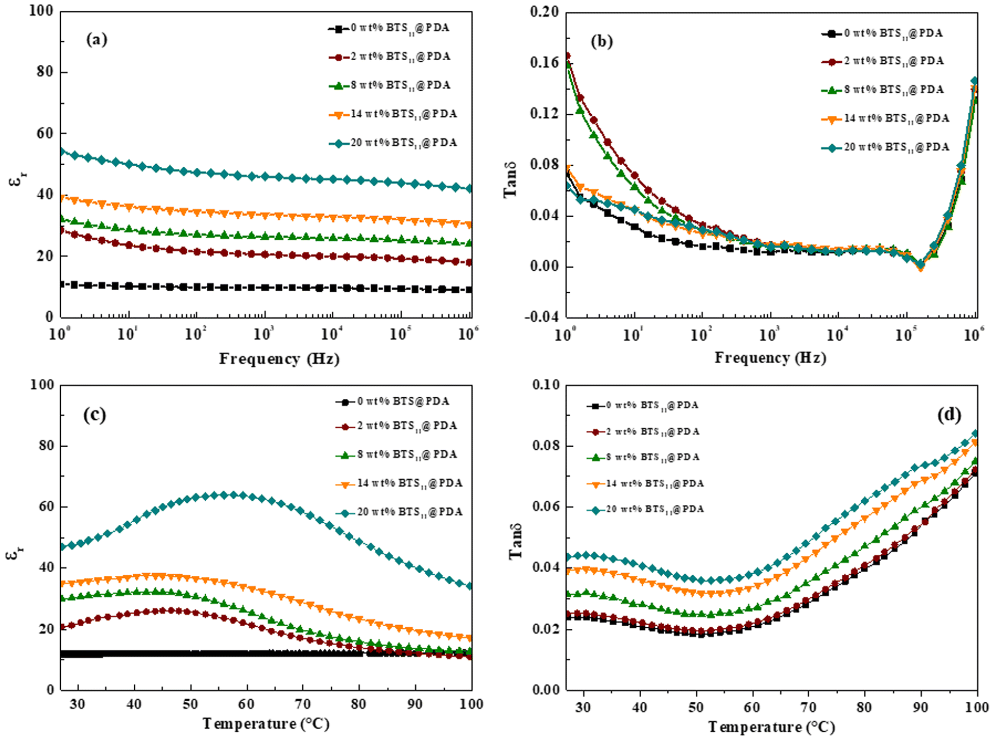 | ||
| Fig. 7 Frequency-dependent (a) dielectric permittivity and (b) dielectric loss of the BTS11@PDA/PVDF-HFP nanocomposites with different filler content. Thermal evolution of the (c) dielectric permittivity and (d) dielectric loss with different filler content at 1 kHz. | ||
The thermal evolution of the dielectric permittivity and the dielectric loss of the BTS11@PDA/PVDF-HFP nanocomposites is depicted in Fig. 7c and d, respectively. The dielectric permittivity is remarkably improved by the filler addition. It is observed that the dielectric permittivity reaches a maximum value of 64 at 54 °C at 20 wt% of the BTS11@PDA while at 45 °C, it attains maximum values of 48, 32 and 26 at 14 wt%, 8 wt%, and 2%, respectively. This aspect may be attributed to the β process, characteristic of the PVDF-HFP polymer.25 On the other hand, as the temperature reaches 60 °C, the tanδ starts increasing with the temperature increase. This arises from the relaxation process associated with the crystalline phase defects. Indeed, inserting BTS11@PDA may produce more crystalline phase defects and impact the relaxation process, resulting in a high dielectric loss at high temperatures.18,46
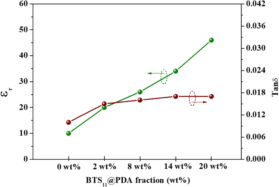
The dielectric permittivity and the dielectric loss in function of the weight fraction of the filler are presented in Fig. 8. The dielectric permittivity remarkably and gradually increases with the increase of the filler content. This is due to the modifier acting as a passivation layer, improving the interfacial polarization while enhancing the filler's dispersion. Meanwhile, the dielectric loss increases slightly when the filler is incorporated into the polymer matrix, starting from 0.010 at 0 wt% to 0.017 at 14 wt%, but interestingly is almost independent of the filler content, indicating a minimized agglomeration of the filler in the composites as seen in Fig. 4c.47
 | ||
| Fig. 8 Dielectric permittivity and dielectric loss of the BTS11@PDA/PVDF-HFP composites as a function of filler percentage at 1 kHz. | ||
Fig. 9 illustrates the comparison between the dielectric permittivity (ε′) and the dielectric loss (tanδ) of two different composites: one containing unmodified 20 wt% of BTS11 nanoparticles dispersed in a PVDF-HFP matrix, and the other composite consisting of modified 20 wt% of BTS11@PDA nanoparticles embedded in the same PVDF-HFP matrix. Dopamine is used to modify BTS11 particles surface. Dopamine's hydroxyl groups strongly interact with the fluorine atoms (–F) in P(VDF-HFP) to produce dipole–dipole interactions. Additionally, because the –F atoms are strongly electronegative, hydrogen bonds (–F⋯OH–) can easily be formed.48 Therefore, the functionalized BTS11 particles exhibit excellent dispersion and compatibility in the PVDF-HFP polymer matrix.
 | ||
| Fig. 9 The dielectric permittivity (a) and the dielectric loss (b) of 20 wt%-BTS11@PDA/PVDF-HFP and 20 wt%BTS11/PVDF-HFP. | ||
Thus, by comparing the dielectric properties of the two composites, the Fig. 9 highlights the impact of PDA coating on the BTS11 nanoparticles. The presence of polydopamine coating on the BTS11 particles is expected to influence the interfacial interactions between the ceramic and the polymer phases (Fig. 9).
The composite with 20 wt%-BTS11@PDA exhibits improved dielectric permittivity and reduced dielectric loss compared to the composite containing the bare BTS11. This enhancement in dielectric performance can be attributed to the enhanced interfacial compatibility achieved through the PDA modification.49
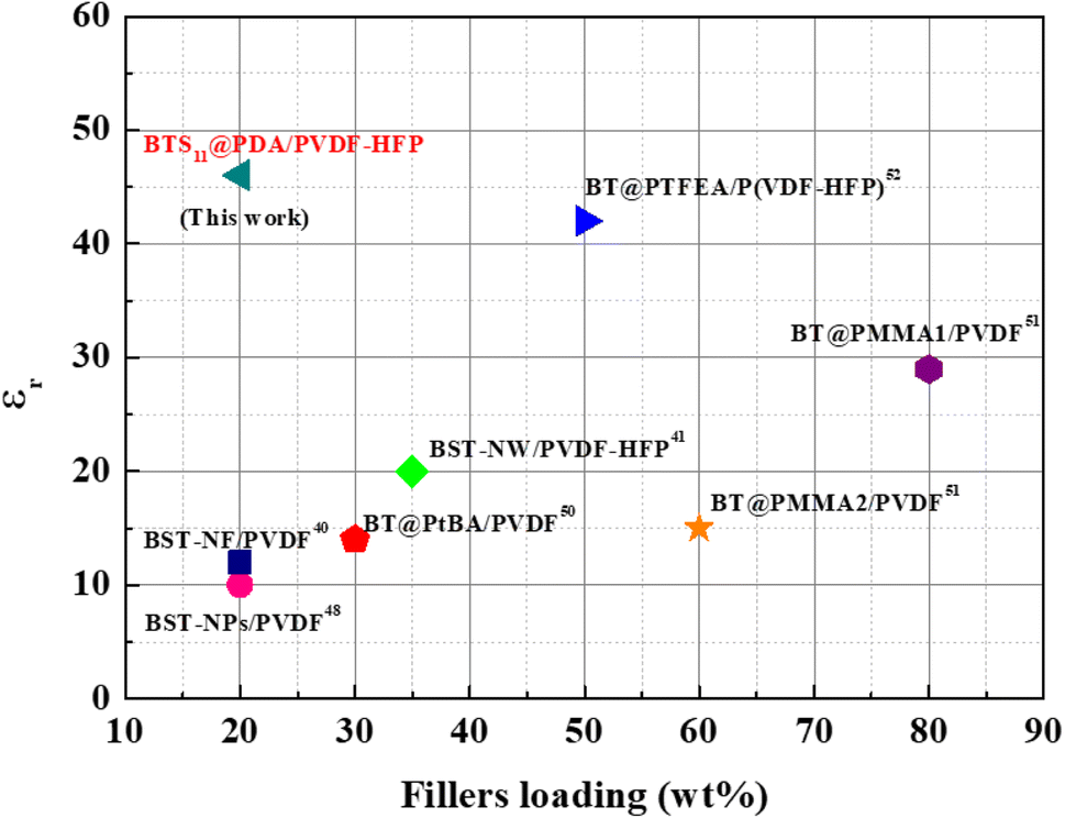
The literature review on the dielectric permittivity of various ceramic/polymer-based nanocomposites is summarized in Fig. 10. Using surface hydroxylated cube-shaped Ba0.6Sr0.4TiO3 nanoparticles (BST-NPs) as fillers and PVDF as the matrix, S. Liu et al. reported ceramic–polymer nanocomposites that achieved a dielectric permittivity of just 10 at 20 wt% of Ba0.6Sr0.4TiO3.50 They later employed Ba0.6Sr0.4TiO3 nanofibers as fillers with a PVDF matrix to improve the properties of the nanocomposites. However, they only achieved a dielectric permittivity of 12 at 20 wt% of Ba0.6Sr0.4TiO3 and 1 kHz.41 Furthermore, Wang et al. also used PVDF-HFP as a polymer matrix with Ba0.7Sr0.3TiO3 nanowires as the ceramic filler and were able to achieve a dielectric permittivity of 20 at 35 wt% of the filler at1 kHz.42 Bi et al. fabricated a three-dimensional BaTiO3 (3D BT)/polyvinylidene fluoride (PVDF) composite dielectrics by inversely introducing PVDF solution into a continuous 3D BT network and reached a dielectric permittivity of 25 at 21.1 wt% of the filler at 100 Hz.51 Du et al. also demonstrated that BaTiO3-PtBA/PVDF nanocomposites can achieve a dielectric permittivity of 14 at 30 wt% of fillers loading at 1 kHz.52 Zhang et al. added significant ceramic filler loading to a PVDF polymer matrix. They employed grafted polymethyl methacrylate (PMMA) in amounts of 5.5% and 8% at BaTiO3, denoted as BT@PMMA1 and BT@PMMA2, respectively. The 80 wt%-BT@PMMA1/PVDF and 60 wt%-BT@PMMA2/PVDF nanocomposites attained a dielectric permittivity of 29 and 15, respectively.53 Last but not least, BT@PTFEA/P(VDF-HFP), a PVDF-HFP nanocomposites with core–shell structured fluoropolymer@BT nanoparticles was reported to reach a dielectric permittivity of 42 at 50 wt% of fillers loading.54 It is noteworthy that our BTS11@PDA/PVDF-HFP nanocomposite which has never been reported in the literature, exhibits the highest dielectric permittivity at low filler content.
 | ||
| Fig. 10 Comparison of the dielectric permittivity at 1 kHz and different fillers loading between different ceramic/polymer-based nanocomposites. | ||
The room-temperature energy storage properties were calculated using the P–E hysteresis loop of the nanocomposites with different wt% of BTS11@PDA fillers (see Fig. 11). The slim aspect of these P–E hysteresis loops is quite remarkable and rarely observed in the ceramic/polymer nanocomposites. For example, at a nanofiller concentration of 20 wt%, the total energy density at 450 kV cmis−1 192 mJ cm−3 is four times more than that of pure PVDF-HFP. The recovered energy for this composition is 134 mJ cm−3 with an efficiency of 72%. Meanwhile, the total energy and recovered energy density of the nanocomposite with 14 wt% BTS11@PDA are 157 mJ cm−3 and 133 mJ cm−3, respectively, reaching an efficiency of 85%. We note that the nanocomposites efficiency is almost independent of filler content until 14 wt% of BTS11@PDA. Beyond this value, it slowly decreases to 72% at 20 wt% of the modified ceramic. The evolution of the Wtot, Wrec, Wloss, and η with the filler weight percentage is depicted in Fig. 10b.
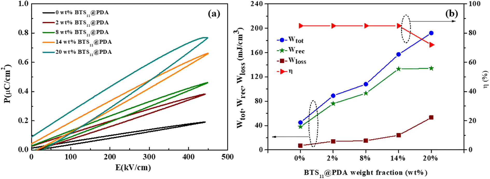 | ||
| Fig. 11 (a) P–E hysteresis loop of the BTS11@PDA/PVDF-HFP nanocomposites with different filler content, and (b) the evolution of the energy storage properties with the filler content. | ||
4. Conclusion
A simple solution casting method is successfully used to synthesize nanocomposites with PDA-modified BTS11 as filler and PVDF-HFP as a polymer matrix. The enhanced dielectric permittivity and low-loss tangents are achieved in the nanocomposites with relatively low weight fractions of surface functionalized BTS11. BTS11@PDA/PVDF-HFP nanocomposites with 20 wt% concentration exhibited the highest dielectric permittivity of 46 with low tanδ ∼0.017 (at 1 kHz), which is the highest value reported so far and is 5 times higher than the pure PVDF-HFP. SEM results show that BTS11@PDA are dispersed homogeneously in the PVDF-HFP polymer matrix. Highly piezo-active regions identified by PFM scanning the composite surface are attributed to the BTS11 nanoparticles. Moreover, the P–E hysteresis loops are ultrafine, resulting in good energy storage properties. At a nanofiller content of 20 wt%, the total energy density is four times higher than that of pure PVDF-HFP with an efficiency of 73%. The findings show that the energy storage density of nanocomposites can be enhanced by adding a small amount of surface-modified ceramic nanoparticles.
Conflicts of interest
The authors declare that they have no known competing financial interests or personal relationships that could have appeared to influence the work reported in this paper.Acknowledgements
The authors gratefully acknowledge the generous financial support of the European Union Horizon 2020 Research and Innovation actions MSCA-RISE-ENGIMA (No. 778072) and MSCA-RISE- MELON (No. 872631). HU and MS acknowledge the Slovenian Research Agency grants (No. 2-0212, P2-0105) and thank Brigita Kmet and Val Fišinger for help in the laboratory. Z. K. acknowledges the Slovenian Research Agency grant P1-0125.References
- Prateek, V. K. Thakur and R. K. Gupta, Chem. Rev., 2016, 116, 4260–4317 CrossRef CAS PubMed.
- Z.-X. Xu, V. A. L. Roy, P. Stallinga, M. Muccini, S. Toffanin and H.-F. Xiang, Appl. Phys. Lett., 2007, 90(22), 223509 CrossRef.
- S. Kumar, S. Supriya and M. Kar, Compos. Sci. Technol., 2018, 157, 48–56 CrossRef CAS.
- Y. N. Hao, K. Bi, S. O'Brien, X. X. Wang, J. Lombardi, F. Pearsall, W. L. Li, M. Lei, Y. Wu and L. T. Li, RSC Adv., 2017, 7, 32886–32892 RSC.
- W. Zhou, G. Cao, M. Yuan, S. Zhong, Y. Wang, X. Liu, D. Cao, W. Peng, J. Liu, G. Wang, Z. Dang and B. Li, Adv. Mater., 2023, 35, 2207829 CrossRef CAS PubMed.
- S. K. Yang, Z. X. Zhang, A. P. Zhang, H. L. Lin, X. T. Zhang, L. X. Xiao, J. Bian and D. Q. Chen, J. Appl. Polym. Sci., 2022, 139(48), e53231 CrossRef CAS.
- W. Li, R. Liang, C. Wu, L. Yang, F. Wang, Z. Liu, X. Chen, H. Mao and W. Zhang, Adv. Mater. Interfaces, 2022, 9, 2201257 CrossRef CAS.
- J. Fu, Y. Hou, M. Zheng, Q. Wei, M. Zhu and H. Yan, ACS Appl. Mater. Interfaces, 2015, 7, 24480–24491 CrossRef CAS PubMed.
- Z. Liang, C.-F. Yan, S. Rtimi and J. Bandara, Appl. Catal., B, 2019, 241, 256–269 CrossRef CAS.
- M. Zahid, O. Kharraz, M. Amjoud, D. Mezzane, M. Gouné, K. Hoummada, I. Saadoune, S. Fourcade, P. Stocker, B. Rožič, Z. Kutnjak and M. El Marssi, Mater. Today Proc., 2022, S2214785322046338 Search PubMed.
- P. T. Thuy Phuong, Y. Zhang, N. Gathercole, H. Khanbareh, N. P. Hoang Duy, X. Zhou, D. Zhang, K. Zhou, S. Dunn and C. Bowen, iScience, 2020, 23, 101095 CrossRef CAS PubMed.
- C. Wang, N. Tian, T. Ma, Y. Zhang and H. Huang, Nano Energy, 2020, 78, 105371 CrossRef CAS.
- Z. Hanani, Nano Energy, 2021, 12 Search PubMed.
- S. Das, A. K. Biswal and A. Roy, IOP Conf. Ser.: Mater. Sci. Eng., 2017, 178, 012020 Search PubMed.
- C. Li, W. Luo, X. Liu, D. Xu and K. He, Nanomaterials, 2016, 6, 67 CrossRef PubMed.
- M.-G. Kang, W.-S. Jung, C.-Y. Kang and S.-J. Yoon, Actuators, 2016, 5, 5 CrossRef.
- R. Pramanik, Ceram. Int., 2019, 12, 5731–5742 CrossRef.
- X. Hu, Y. Zhou, J. Liu and B. Chu, J. Appl. Phys., 2018, 123(15), 154101 CrossRef.
- C. E. Ciomaga, N. Horchidan, L. Padurariu, R. S. Stirbu, V. Tiron, F. M. Tufescu, I. Topala, O. Condurache, M. Botea, I. Pintilie, L. Pintilie, A. Rotaru, G. Caruntu and L. Mitoseriu, Ceram. Int., 2022, S0272884222018429 Search PubMed.
- H. Bai, G. Ge, X. He, B. Shen, J. Zhai and H. Pan, Compos. Sci. Technol., 2020, 195, 108209 CrossRef CAS.
- B. K. Pandey, A. Kumar, K. P. Chandra, A. R. Kulkarni, S. K. Jayaswal and K. Prasad, J. Adv. Dielectr., 2018, 08, 1850027 CrossRef.
- G. A. Kaur, S. Kumar and M. Shandilya, J. Mater. Sci. Mater. Electron., 2020, 31, 20303–20314 CrossRef.
- S. P. P. Sadhu, S. Siddabattuni, S. Muthukumar and K. B. R. Varma, J. Mater. Sci. Mater. Electron., 2018, 29, 6174–6182 CrossRef CAS.
- M. Zahid, Y. Hadouch, M. Amjoud, D. Mezzane, M. Gouné, K. Hoummada, A. Alimoussa, A. G. Razumnaya, B. Rožič and Z. Kutnjak, J. Mater. Sci. Mater. Electron., 2022, 33, 12900–12911 CrossRef CAS.
- X. Lu, X. Zou, J. Shen, L. Jin, F. Yan, G. Zhao, L. Zhang and Z.-Y. Cheng, Ceram. Int., 2019, 45, 17758–17766 CrossRef CAS.
- A. Issa, M. Al-Maadeed, A. Luyt, D. Ponnamma and M. Hassan, C, 2017, 3, 30 Search PubMed.
- Z. Li, F. Liu, G. Yang, H. Li, L. Dong, C. Xiong and Q. Wang, Compos. Sci. Technol., 2018, 164, 214–221 CrossRef CAS.
- W. Mei, J. Wei, Z. Ko, Z.-Y. Cheng and J. Hu, Ceram. Int., 2021, 47, 15561–15567 CrossRef CAS.
- H. Uršič and U. Prah, Proc. R. Soc. A, 2019, 475, 20180782 CrossRef PubMed.
- Q. Zhao, H. Xiao, G. Huangfu, Z. Zheng, J. Wang, F. Wang and Y. Guo, Nano Energy, 2021, 85, 106028 CrossRef CAS.
- J. Gao, Y. Wang, Y. Liu, X. Hu, X. Ke, L. Zhong, Y. He and X. Ren, Sci. Rep., 2017, 7, 40916 CrossRef CAS PubMed.
- C.-C. Li, S.-J. Chang, J.-T. Lee and W.-S. Liao, Colloids Surf., A, 2010, 361, 143–149 CrossRef CAS.
- R. Kota and B. I. Lee, J. Mater. Sci. Mater. Electron., 2007, 18, 1221–1227 CrossRef CAS.
- S. Dash, V. N. Thakur, A. Kumar, R. N. Mahaling, S. Patel, R. Thomas, B. Sahoo and D. K. Pradhan, Ceram. Int., 2021, 47, 33563–33576 CrossRef CAS.
- T. Zhou, J.-W. Zha, R.-Y. Cui, B.-H. Fan, J.-K. Yuan and Z.-M. Dang, ACS Appl. Mater. Interfaces, 2011, 3, 2184–2188 CrossRef CAS PubMed.
- Y. Xie, Y. Yu, Y. Feng, W. Jiang and Z. Zhang, ACS Appl. Mater. Interfaces, 2017, 9, 2995–3005 CrossRef CAS PubMed.
- P. Hu, S. Gao, Y. Zhang, L. Zhang and C. Wang, Compos. Sci. Technol., 2018, 156, 109–116 CrossRef CAS.
- Y. Li, J. Yuan, J. Xue, F. Cai, F. Chen and Q. Fu, Compos. Sci. Technol., 2015, 118, 198–206 CrossRef CAS.
- H. Luo, J. Roscow, X. Zhou, S. Chen, X. Han, K. Zhou, D. Zhang and C. R. Bowen, J. Mater. Chem. A, 2017, 5, 7091–7102 RSC.
- C. Wang, J. Zhang, S. Gong and K. Ren, J. Appl. Phys., 2018, 124, 154103 CrossRef.
- S. Liu, S. Xiao, S. Xiu, B. Shen, J. Zhai and Z. An, RSC Adv., 2015, 5, 40692–40699 RSC.
- S. Wang, X. Huang, G. Wang, Y. Wang, J. He and P. Jiang, J. Phys. Chem. C, 2015, 119, 25307–25318 CrossRef CAS.
- S. Liu, S. Xue, W. Zhang, J. Zhai and G. Chen, J. Mater. Chem. A, 2014, 2, 18040–18046 RSC.
- G. Chen, X. Wang, J. Lin, W. Yang, H. Li and Y. Wen, J. Phys. Chem. C, 2016, 120, 28423–28431 CrossRef CAS.
- R. Tamura, E. Lim, T. Manaka and M. Iwamoto, J. Appl. Phys., 2006, 100, 114515 CrossRef.
- K. Yu, H. Wang, Y. Zhou, Y. Bai and Y. Niu, J. Appl. Phys., 2013, 113, 034105 CrossRef.
- L. Shaohui, Z. Jiwei, W. Jinwen, X. Shuangxi and Z. Wenqin, ACS Appl. Mater. Interfaces, 2014, 6, 1533–1540 CrossRef PubMed.
- Y. Niu, Y. Bai, K. Yu, Y. Wang, F. Xiang and H. Wang, ACS Appl. Mater. Interfaces, 2015, 7, 24168–24176 CrossRef CAS PubMed.
- H. Hu, F. Zhang, S. Lim, P. Blanloeuil, Y. Yao, Y. Guo and C. H. Wang, Composites, Part B, 2019, 178, 107459 CrossRef CAS.
- S. Liu, S. Xiu, B. Shen, J. Zhai and L. Kong, Polymers, 2016, 8, 45 CrossRef PubMed.
- X. Bi, L. Yang, Z. Wang, Y. Zhan, S. Wang, C. Zhang, Y. Li, Y. Miao and J. Zha, Materials, 2021, 14, 3585 CrossRef CAS PubMed.
- X. Du, Y. Liu, J. Wang, H. Niu, Z. Yuan, S. Zhao, X. Zhang, R. Cao, Y. Yin, N. Li, C. Zhang, Y. Xing, W. Xu and C. Li, ACS Appl. Mater. Interfaces, 2018, 10, 25683–25688 CrossRef CAS PubMed.
- X. Zhang, S. Zhao, F. Wang, Y. Ma, L. Wang, D. Chen, C. Zhao and W. Yang, Appl. Surf. Sci., 2017, 403, 71–79 CrossRef CAS.
- K. Yang, X. Huang, Y. Huang, L. Xie and P. Jiang, Chem. Mater., 2013, 25, 2327–2338 CrossRef CAS.
| This journal is © The Royal Society of Chemistry 2023 |