DOI:
10.1039/D3RA03834C
(Paper)
RSC Adv., 2023,
13, 28984-28992
Synergistic activation of persulfate by a manganese cobalt oxide/reduced graphene oxide nanocomposite with enhanced degradation of trichloroethylene†
Received
8th June 2023
, Accepted 22nd August 2023
First published on 4th October 2023
Abstract
Advanced oxidation technology based on persulfate is one of the most reliable and effective technologies for the degradation of wastewater, however the key lies in developing highly efficient catalysts to activate persulfate. Herein, manganese cobalt oxide/reduced graphene oxide (MnCo2O4/rGO) nanocomposites were successfully synthesized via a facile solvothermal method and employed as a highly efficient catalyst to active persulfate for the degradation of trichloroethylene (TCE). The rGO nanosheets have large surface areas, which can increase the contact area with reactants and make the degradation more efficient. Additionally, the MnCo2O4 nanoparticles are in situ grown on the surface of ultrathin rGO nanosheets, endowing the material with high structural porosity and fast transport channels, and are beneficial for the improvement of catalytic sites and the transport of catalysis-relevant species. More importantly, the close contact between MnCo2O4 nanoparticles and rGO nanosheets synergistically favors the electron transfer, thereby accelerating the electron transfer, improving the activation efficiency, and promoting the generation of sulfate radicals (·SO4−). rGO can also reduce the spillover of metal ions. The kinetics model and degradation mechanism of the nanocomposites are also proposed.
Introduction
Trichloroethylene (TCE) is a common volatile organic compound (VOC) with unique solvent properties that make it suitable for a wide range of industrial applications.1 Since the early 20th century, TCE has been widely used as an industrial degreasing solvent, as well as for dry cleaning and food processing, and as a raw material for printing inks and paints, in addition to its use as a general anesthetic or analgesic. Although TCE is not naturally occurring in the environment, it still can be found in underground and surface waters as a result of its manufacture, use, and treatment.2 However, TCE can pose a serious threat to human health when released into the environment, as it has been shown to be carcinogenic and mutagenic, and can cause chronic diseases such as vertigo, tremors, nausea, fatigue, sleepiness, liver cancer, hepatitis, and heart failure.3 Therefore, due to its various shortcomings, the importance of TCE treatment cannot be overstated.
Given the widespread prevalence of TCE in the environment and its adverse effects on human health, numerous methods have been developed to remove and decompose TCE from contaminated water, air, and soil media over the past few decades.4–8 Physical methods can only achieve TCE degradation efficiency of up to about 67%,9 while biodegradation and chemical methods can achieve a higher efficiency.10,11 The most commonly used physical methods are adsorption and membrane filtration technology, with activated carbon adsorption technology being developed in the early stages for trichloroethylene.10 However, physical methods only transfer pollutants from one medium to another without destroying them, which may cause secondary pollution. Biodegradation methods, on the other hand, decompose and transform chlorinated pollutants using the metabolic activities of microorganisms in nature. Biodegradation methods are advantageous as they are low cost, do not produce secondary pollution, but have a long degradation period and difficult temperature control issues that need addressing.11,12 For chemical methods, it involves adding chemicals to the water to separate pollutants from the water or applying external energy to promote the reaction of pollutants for decomposition. This method includes incineration,13 photocatalytic oxidation,14 nano zero valent iron reduction,15 and advanced oxidation.16 Although incineration can remove pollutants in a short time, it is costly, requires a large amount of external energy, and produces highly toxic products. Photocatalysts have shortcomings such as a wide band gap energy, low light absorption capacity, and fast recombination rate, leading to a small number of photogenerated active free radical available for photodegradation at the surface reaction site, hindering practical application. Nano zero-valent iron agglomerates easily, resulting in a sharp decline in reactivity and causing secondary pollution in the repair process, leading to high economic costs. Particularly, advanced oxidation technology is preferred due to its simplicity, environmental compatibility, and versatility.
Recently, reactive persulfate (PS) has received attention in water and wastewater treatment due to its longer half-life, stronger oxidation, higher electrode potential, and wider pH range.17,18 Compared to the hydroxyl radical, sulfate radicals (·SO4−) has a more extended half-life (30–40 μs), stronger oxidation, higher electrode potential (E0 = 2.6–3.2 V), and wider pH range (2–8), making the sulfate radical method more effective in degrading TCE in water. In previous research, the oxidation of PS has been shown to rely on the creation of highly active sulfate radicals. These sulfate radicals can be produced through various methods such as thermal treatment,19–21 photolysis,22 acoustic activation,23 radioactive activation,24 and the reaction of PS with transition metal oxide composites.25,26 Compared to other methods that require external energy input, a transition metal catalyst can activate persulfate at room temperature and pressure without the need for additional energy. Previous studies have identified divalent cobalt as the most effective catalyst to activate PS.27,28 For instance, studies by Chen et al.29 and Muhammad et al.30 have used Co3O4 as a catalyst to active peroxydisulfate (PDS) to degrade acid orange 7 and phenol. Reduced graphene oxide (rGO) is another effective carrier material for catalytic degradation of pollutants in water. The combination of catalyst and rGO offers numerous advantages, including high surface area and tensile strength, improved electronic conductivity and mobility, lightweight, and high stability.31,32 However, to our knowledge, few studies have investigated the activation of persulfate by MnCo2O4/rGO for the degradation of TCE.
Herein, we prepared MnCo2O4/rGO composites using a two-step solvothermal method and employed them as a catalyst to activate persulfate for the degradation of TCE. Benefiting from the merits of structure and composites of the as-prepared sample, including large surface area, high structural porosity, fast transport channels, and the synergistic effect between MnCo2O4 nanoparticles and rGO nanosheets, enabling the degradation efficiency of TCE to reach 95% within 4 h under the optimal reaction conditions. Additionally, we also studied the degradation efficiency of TCE under different conditions in the reaction system and analyzed the mechanism of MnCo2O4/rGO activation of persulfate to understand the degradation pathway of TCE.
Experimental section
Reagents and chemicals
Manganese acetate tetrahydrate (Mn(Ac)2·4H2O) and cobalt acetate tetrahydrate (Co(Ac)2·4H2O) were purchased from Aladdin Biochemical Technology Co., LTD. Potassium persulfate (K2S2O4), purchased from Macklin Co., LTD. Trichloroethylene (TCE), ammonium fluoride (NH4F), graphite powder (C), potassium permanganate (KMnO4), sodium nitrate (NaNO3), hydrogen peroxide (H2O2), ethanol (99.5%), ethylene glycol (99.7%), sulfuric acid were purchased from Sinopharm Chemical Reagent Co., LTD. All reagents were used without further purification.
Synthesis of manganese cobalt oxide (MnCo2O4) nanoparticle
The MnCo2O4 nanoparticles were prepared via a solution-based method. Typically, 1.471 g of Mn(Ac)2·4H2O and 2.989 g of Co(Ac)2·4H2O were added to 45 mL ethylene glycol and 15 mL de-ionized water with stirring for 5 min. Then, 1.34 g of NH4F was added into the above solution with continue stirring for 2 h. After that, the mixture was transferred to a 100 mL Teflon-lined autoclave and kept at 180 °C for 16 h. Being cooled to ambient temperature, the resulting mixture was centrifugalized and the solids were washed with de-ionized water and ethanol for several times, and dried under vacuum at 80 °C for 16 h. Finally, the resulting product was calcined in Muffle furnace at 400 °C for 2 h at a heating rate of 2 °C min−1.
Synthesis of MnCo2O4/rGO nanocomposite
To prepare MnCo2O4/rGO nanocomposite, graphene oxide (GO) was firstly prepared by the modified Hummers' method.33 Then, 30, 60, 90 mg of the as-prepared GO was added into a mixed solvent of 45 mL of ethylene glycol and 15 mL de-ionized water with ultrasonic treatment to form a GO solution. Subsequently, 1.0 g of MnCo2O4 was added into the GO solution with stirring for 2 h. The mixture was transferred to a 100 mL Teflon-lined autoclave and kept at 180 °C for 10 h. After cooling to room temperature, the product of MnCo2O4/rGO nanocomposite was collected by centrifugation and washed with de-ionized water and ethanol for several times and finally dried under vacuum at 80 °C for 24 h.
Experimental procedure
To simulate the dark conditions of groundwater, all catalytic degradation studies were performed in a 250 mL beaker in the dark. The beaker contained 200 mL of 0.15 mM TCE solution. A mechanical stirring arm was used to stir the solution and sample it at a certain time (1, 2, 3, 4 h) at room temperature. The pH of aqueous solution of TCE was adjusted with dipotassium hydrogen phosphate (pH = 9, 11) and sulfuric acid (pH = 3). Then, a certain amount (0.05, 0.1, 0.2, 0.3, 0.4 g L−1) of MnCo2O4/rGO composite material and PS were added to the solution for reaction. Samples of 3 mL were taken at fixed intervals and filtered (0.22 μm membrane) to obtain the samples to be tested.
In order to verify the efficient degradation of TCE by MnCo2O4/rGO/PS, the degradation efficiency of TCE by MnCo2O4, MnCo2O4/rGO, PS, MnCo2O4/PS and MnCo2O4/rGO/PS was compared. The factors such as the amount of catalyst, the amount of PS, the initial pH and the presence of anions were investigated to optimize the activation conditions of MnCo2O4/rGO/PS system. In order to evaluate the stability and reusability of the catalyst, the MnCo2O4/rGO nanocomposite is centrifugally collected after each reaction, cleaning with ethanol and DI water, then dried in the drying oven. In order to investigate the reaction mechanism, two different free radical scavengers were used to determine the type of free radicals formed in the MnCo2O4/rGO/PS system. All the above experiments were performed three times and the results were averaged.
To get insights into the degradation pathway and mechanism, the concentration of TCE and their degradation intermediates was determined using gas chromatography-mass spectrometry (GC-MS) with a purge and capture device, employing a DB-VRX column. Specific GC-MS parameters were employed for the analysis. The purge trap parameters included a purge flow rate of 40 mL min−1, a purge time of 11 min, dry purge time of 1 min, pre-desorption temperature of 180 °C, desorption temperature of 190 °C, desorption time of 2 min, baking temperature of 200 °C, and baking time of 6 min. Shunt injection (30![[thin space (1/6-em)]](https://www.rsc.org/images/entities/char_2009.gif) :1) was utilized as the injection method for gas chromatography. The inlet temperature was set at 220 °C, and the temperature program was as follows: it was kept at 35 °C for 2 min, then increased to 120 °C at 5 °C min−1, and finally raised to 220 °C at 10 °C min−1 for 2 min. Helium was used as the carrier gas with a flow rate of 1 mL min−1. For mass spectrometry, the EI source was employed, with an ion source temperature of 230 °C and an ionization energy of 70 eV. The scanning mode was SIM ion scan, and the solvent delay was set to 2 min. The electron doubling voltage was consistent with the tuning voltage, and the interface temperature was maintained at 280 °C.
:1) was utilized as the injection method for gas chromatography. The inlet temperature was set at 220 °C, and the temperature program was as follows: it was kept at 35 °C for 2 min, then increased to 120 °C at 5 °C min−1, and finally raised to 220 °C at 10 °C min−1 for 2 min. Helium was used as the carrier gas with a flow rate of 1 mL min−1. For mass spectrometry, the EI source was employed, with an ion source temperature of 230 °C and an ionization energy of 70 eV. The scanning mode was SIM ion scan, and the solvent delay was set to 2 min. The electron doubling voltage was consistent with the tuning voltage, and the interface temperature was maintained at 280 °C.
Characterization
X-ray diffraction (XRD) patterns of the products were acquired using a D/Max-2004 X-ray powder diffractometer (Bruker, Germany) with 2θ ranging from 10° to 80°. The morphologies and crystal structure of the catalysts were characterized via the scanning electron microscope (SEM, ZEISS Sigma 300) and transmission electron microscopy (TEM, JEOL JEM 2100, 200 kV). Brunauer–Emmett–Teller (BET) surface area of the samples were collected by N2 adsorption–desorption method at 77 K on the ASAP 2010 instrument (Micromeritics ASAP2460). X-ray photoelectron spectra (XPS, Thermo Scientific K-Alpha) was applied to detect the surface elements.
Results and discussion
Microstructural analysis
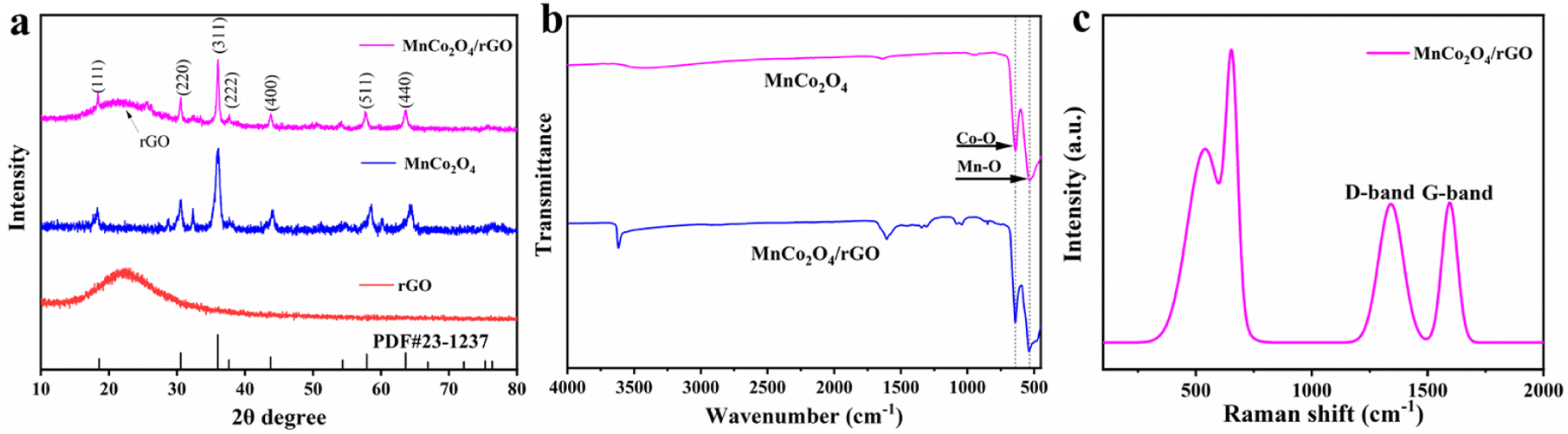
Fig. 1a displays the XRD patterns of the as-synthesized rGO, MnCo2O4, and MnCo2O4/rGO composites. The (002) peak of rGO shows broadening and reduced intensity, indicating the formation of a highly disordered and defect-rich structure in the nanosheets. The cubic phase of MnCo2O4 is characterized by lattice constants of a = b = c = 8.269 Å (JCPDS no. 23-1237), and the diffraction peaks at 2θ of 18.3°, 30.2°, 35.6°, 37.00°, 43.2°, 57.2°, and 62.7° correspond to the (111), (220), (311), (222), (400), (511), and (440) planes. It confirms the spinel structure of MnCo2O4/rGO. Coupling MnCo2O4 with rGO does not affect the diffraction peaks of MnCo2O4, which remain clear and show a similar XRD pattern to that of MnCo2O4. Notably, rGO shows no distinct diffraction peaks due to the low quantity and relatively low diffraction intensity of rGO nanosheets. These results suggest the successful synthesis of MnCo2O4/rGO composites. Additionally, the Scherrer formula estimated the average grain size of MnCo2O4 nanoparticles to be within the range of 4.5 nm, consistent with the TEM result presented below.
 |
| | Fig. 1 (a) XRD patterns of the as-synthesized rGO, MnCo2O4 and MnCo2O4/rGO samples; (b) FT-IR spectroscopy of MnCo2O4 and MnCo2O4/rGO samples; (c) Raman spectroscopy of MnCo2O4/rGO sample. | |
The FT-IR spectra of MnCo2O4 and MnCo2O4/rGO are presented in Fig. 1b. The observed peaks at approximately 3600 cm−1, 1600 cm−1, 1300 cm−1, and 1200 cm−1 can be attributed to residual oxygen and structural defects on the rGO. Furthermore, two distinct and sharp absorption bands at 551 cm−1 and 638 cm−1 are observed, originating from the stretching vibrations of the metal–oxygen bonds. Specifically, the 542 cm−1 (νo) band corresponds to the Co3+/Mn3+ vibrations in the Oh complexes, while the 629 cm−1 (νt) band is associated with the Co2+ vibrations in the Td complexes of the spinel lattice.
The Raman spectra of MnCo2O4/rGO are depicted in Fig. 1c, illustrating the characteristic bands known as the G band and D band, which originate from carbon vibrations. The D band, observed at 1355 cm−1, exhibits symmetry with A1g and corresponds to photons near the boundary of the K region. The peak at 1598 cm−1 signifies the composite structure of rGO nanosheets, with the corresponding Raman active state of the G band identified as E2g. Moreover, the Raman mode at approximately 691 cm−1 (A1g) can be attributed to the distinctive characteristics of octahedral (Co–O6) sites, while the mode at around 533 cm−1 (F32g) corresponds to tetrahedral (Co–O4) sites.34 These results confirm the successful synthesis of the MnCo2O4/rGO compound.
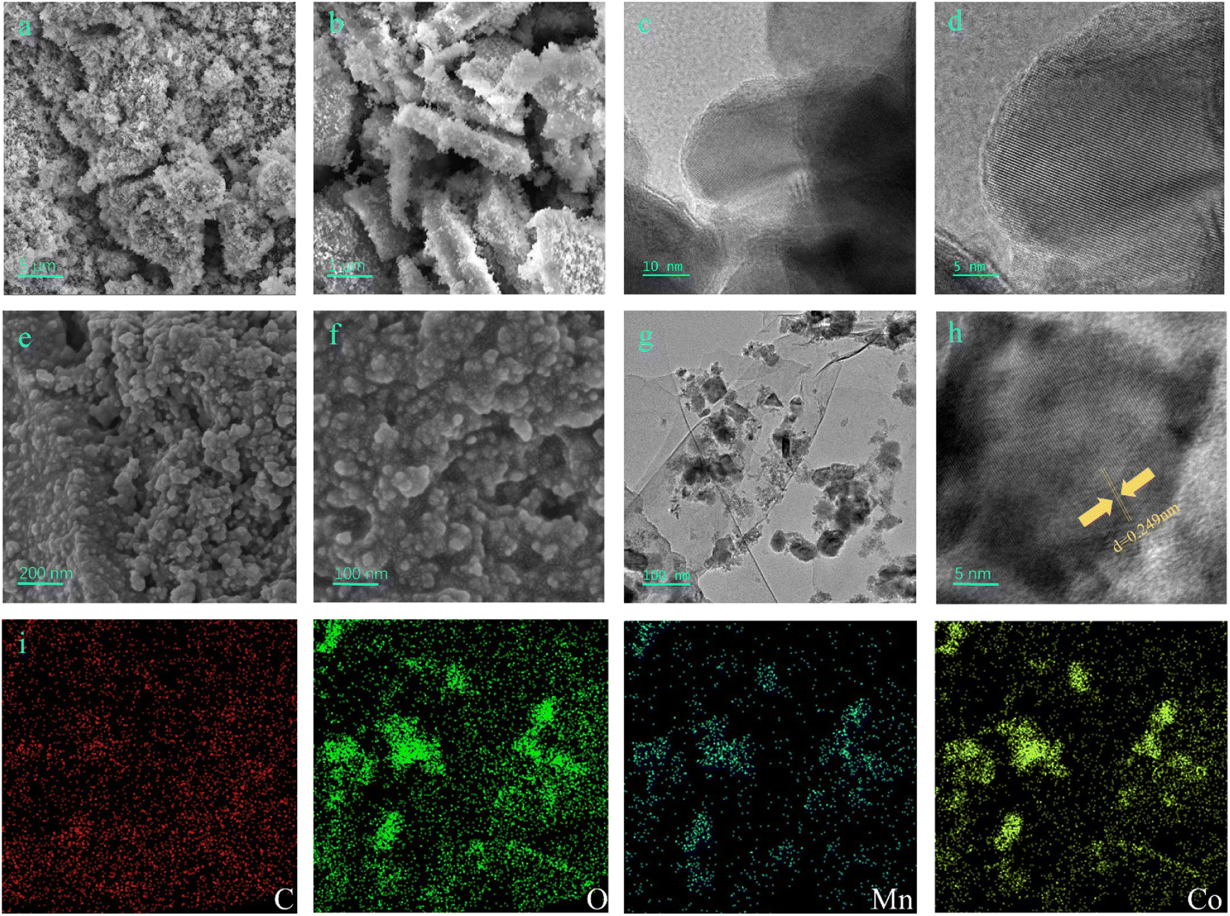
The morphology and microstructure of MnCo2O4 and MnCo2O4/rGO nanocomposites were analyzed in detail using field emission scanning electron microscopy (FESEM) and transmission electron microscopy (TEM). SEM images (Fig. 2a and b) revealed the spinel structure of MnCo2O4 nanoparticles. Lattice fringes were observed in the TEM images (Fig. 2c and d). The SEM images in Fig. 2e and f demonstrated that the MnCo2O4/rGO nanocomposites consisted of rGO nanosheets and MnCo2O4 nanoparticles. The TEM image in Fig. 2g further confirmed the presence of irregular sheet-like morphologies and the existence of rGO in the sample. A high-resolution TEM image (Fig. 2h) showed that MnCo2O4 nanoparticles were deposited on the surface of rGO nanosheets, which can reduce the restacking of rGO nanosheets and increase the contact area with reactants, resulting in better catalytic performance. The MnCo2O4 nanoparticles exhibited high crystallinity, as confirmed by the clear lattice fringes with d-spacings of 0.249 nm corresponding to the (311) planes of MnCo2O4 (Fig. 2h). The EDX results (Fig. 2i) indicated the presence of Mn, Co, C, and O elements in the sample, with a relatively uniform distribution.
 |
| | Fig. 2 SEM (a) and (b), TEM (c) and HRTEM (d) images of MnCo2O4 nanoparticle, SEM (e) and (f), TEM (g), HRTEM (h) and STEM-EDX (i) images of the as-synthesized MnCo2O4/rGO nanocomposite. | |
BET analysis
By analyzing the N2 adsorption and desorption isotherms and the pore-size distribution of the as-synthesized MnCo2O4 and MnCo2O4/rGO samples, the BET surface area and detailed pore structure were determined (Fig. 3). It was found that the MnCo2O4/rGO sample has a larger BET specific surface area of 43.9 m2 g−1 than that of pristine MnCo2O4 nanoparticles (35.7 m2 g−1). Additionally, the pore volume of the MnCo2O4/rGO sample (0.27 cm3 g−1) is also larger than the bare MnCo2O4 nanoparticles (0.21 cm3 g−1). These results indicate that the RGO layer is flaked and wrinkled due to the insertion of MnCo2O4 nanoparticles, leading to an increase in specific surface area and the formation of micro-mesoporous pores.
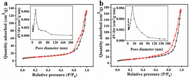 |
| | Fig. 3 Nitrogen adsorption–desorption isotherm plots of (a) MnCo2O4 and (b) MnCo2O4/rGO and BJH pore distribution (inset). | |
Degradation performance
Catalytic evaluation. The as-synthesized MnCo2O4/rGO composite was utilized as a highly efficient catalyst to activate persulfate for TCE degradation. The degradation of TCE was investigated under different reaction conditions, and the TCE concentration changes were recorded, as shown in Fig. 4a. It was observed that MnCo2O4 had no discernible effect on TCE degradation without the addition of persulfate, whereas MnCo2O4/rGO showed a certain degree of degradation effect. This can be attributed to the presence of rGO, which can react with TCE and promote its degradation.32 In contrast, persulfate alone degraded only 40% of TCE after a reaction time of 4 h. However, when MnCo2O4 was added, the TCE degradation efficiency was significantly improved, reaching 71%, indicating that persulfate can be effectively activated by Mn(II) and Co(III). Moreover, the use of MnCo2O4/rGO as a catalyst further enhanced the TCE degradation efficiency to 95%. This enhanced efficiency can be attributed to the higher electron mobility of rGO and the larger specific surface area of the composite, which expose more active sites and thus improve the reaction efficiency.35
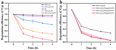 |
| | Fig. 4 Degradation efficiency of TCE in different systems (a) and effect of rGO loading on TCE degradation (b) [reaction conditions: persulfate concentration = 0.3 g L−1, catalyst dosage = 0.3 g L−1, reaction temperature = 25 °C and initial pH value = 6 (unadjusted)]. | |
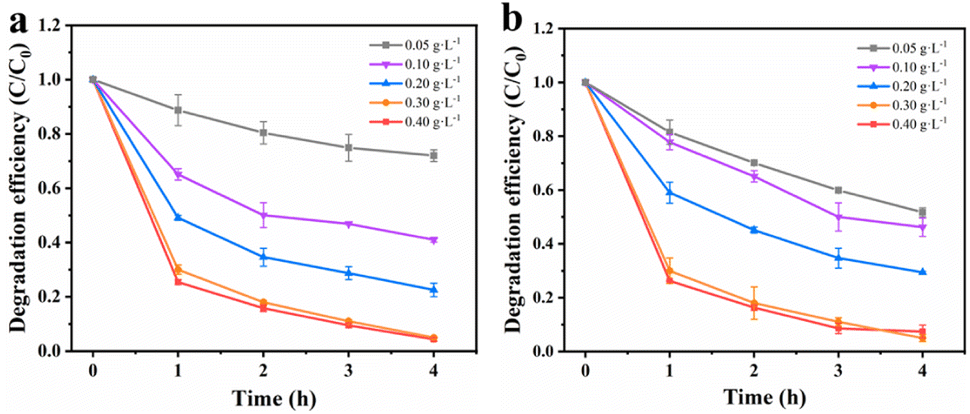
Effects of rGO loading. Firstly, the degradation efficiency of MnCo2O4/rGO composites prepared with different rGO loads (30, 60, 90 mg) was investigated. As shown in Fig. 4b, the degradation efficiency reached 94.3%, 95.1% and 95.5% respectively after 4 hours. It can be seen that the load of rGO has little effect on the degradation efficiency. When the load of rGO is 30 mg, the degradation efficiency is increased because rGO improves the electron transfer rate. When the loading capacity of rGO is 60 mg and 90 mg, the degradation efficiency is further improved due to the adsorption and interaction of MnCo2O4/rGO. In order to avoid incomplete degradation caused by excessive adsorption of rGO on TCE, 60 mg of rGO was selected to be combined with MnCo2O4.
Effects of catalyst dosage. To maximize the degradation efficiency, the dosage of catalysts was optimized. Fig. 5a illustrates the impact of different amounts of MnCo2O4/rGO on TCE degradation at a constant persulfate concentration. It is evident that the degradation efficiency of TCE increases significantly with higher dosages of MnCo2O4/rGO. At a dosage of 0.3 g L−1, the degradation efficiency reaches its maximum, approximately 95%, due to the increased number of active sites available for the reaction.36 Notably, even at a dosage of 0.4 g L−1, the degradation efficiency continues to increase. The higher dosage results in a greater number of active sites, thereby enhancing the degradation efficiency. To balance economic considerations and minimize metal spillover, a catalyst dosage of 0.3 g L−1 was selected as the optimal reaction condition.
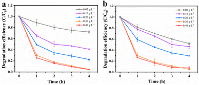 |
| | Fig. 5 Effect of reaction parameters on TCE degradation: (a) catalyst dosage [PS dosage = 0.3 g L−1] and (b) PS dosage [catalyst dosage = 0.3 g L−1] [reaction conditions: reaction temperature = 25 °C and initial pH value = 6 (unadjusted)]. | |
Effects of PS dosage. Previous studies have shown that the concentration of persulfate has a significant impact on the removal of target substances during reactions. As a sequence, the degradation efficiency of TCE in the MnCo2O4/rGO/PS system at various persulfate concentrations (0.05, 0.1, 0.2, 0.3, and 0.4 g L−1) was investigated. As depicted in Fig. 5b, when the MnCo2O4/rGO dosage is 0.3 g L−1, the degradation efficiency of TCE increases from 21% to 95% with the increase in persulfate concentration. This suggests that higher persulfate concentrations lead to better degradation of TCE. However, at higher concentrations, the increase can inhibit the removal of the target due to the recombination of excess ·SO4− and the self-depletion caused by the reaction between ·SO4− and excess S2O82−. Therefore, a persulfate concentration of 0.3 g L−1 was chosen as the optimal reaction condition based on cost and environmental considerations.| | |
·SO4− + SO4˙− → S2O82−
| (1) |
| | |
·SO4− + S2O82− → SO42− + S2O8˙−
| (2) |
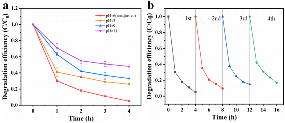
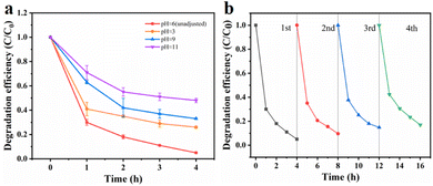
Effects of initial pH. Fig. 6a illustrates the degradation efficiency of TCE at different pH values. It was observed that pH had a significant impact on the degradation of organic pollutants by sulfate free radicals. To investigate this effect, we adjusted the pH of the solution using sulfuric acid and dipotassium hydrogen phosphate, resulting in pH values of 3, 9 and 11. It was observed that the degradation efficiency of TCE was lower than normal under extremely acidic or alkaline conditions. This can be attributed to the susceptibility of the MnCo2O4 spinel structure to collapse under highly acidic conditions, thereby reducing its catalytic activity. Similarly, under alkaline conditions, the reaction between ·SO4− and OH− leads to the formation of hydroxyl radicals with lower reactivity, shorter half-life, and diminished activation ability, as described in formula (3). Furthermore, when the pH exceeds 9, the decomposition of MnCo2O4 may occur, resulting in the formation of manganese and cobalt hydroxides, which in turn affects the degradation efficiency of trichloroethylene. Therefore, a pH of approximately 6 was determined as the optimal reaction condition for this experiment.| | |
·SO4− + OH− → SO42− + OH˙
| (3) |
| | |
·SO4− + H2O → HSO4− + OH˙
| (4) |
| | |
S2O82− + H2O2 → 2SO42− + O2 + 2H+
| (6) |
 |
| | Fig. 6 Effect of reaction parameters on TCE degradation: initial pH value (a) and reusability of MnCo2O4/rGO as a catalyst activated PS for the degradation of TCE (b) [reaction conditions: PS dosage = 0.3 g L−1, catalyst dosage = 0.3 g L−1 and reaction temperature = 25 °C]. | |
Reusability and stability of MnCo2O4/rGO catalyst. The cyclic performance of the MnCo2O4/rGO catalyst was assessed through a series of experiments. After each reaction, the catalyst was collected by centrifugation, followed by washing with ethanol and DI water, and subsequent drying in an oven. The treated catalyst was then reintroduced into the solution under identical conditions as the initial experiment for a second degradation experiment. This process was repeated three times to investigate any variations in the catalytic efficiency of the catalyst after each reaction. Fig. 6b demonstrates that even after three consecutive reactions, the degradation efficiency of trichloroethylene only decreased to 83% by the fourth reaction. This decrease in activity can be attributed to the consumption and leaching of metal ions into the solution during the reaction, as well as the absorption of certain reaction intermediates by the material. These factors result in a reduction in available catalytic active sites and the partial deterioration of the material structure after multiple reactions.35
Degradation mechanism of TCE
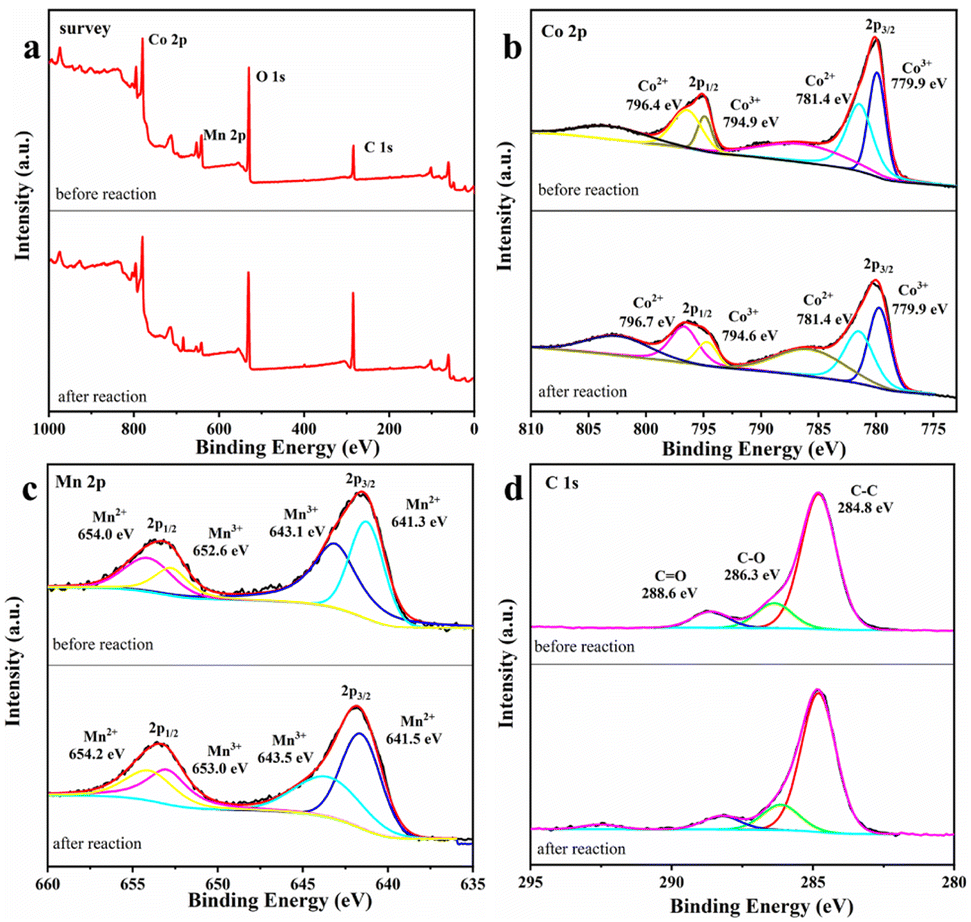
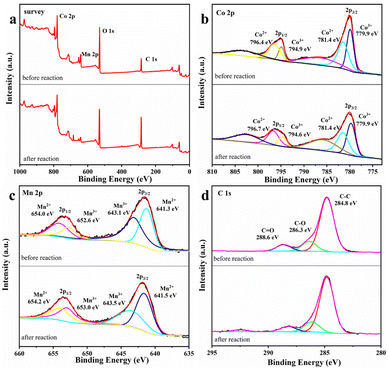
XPS characterization of MnCo2O4/rGO. It is considered that the catalytic process may cause the changes in the elemental valence of the catalyst, thus it is necessary to evaluate the surface properties of MnCo2O4/rGO after the reaction. Fig. 7 shows the changes of the valence states of the main elements of the material before and after the reaction. The survey spectrum of the sample is presented in Fig. 7a, indicating the primary chemical compositions of C, O, Mn, and Co elements. In Fig. 7b, the Co 2p spectrum shows two main photoelectron peaks, with binding energies of 780.0 eV and 795.3 eV, corresponding to the binding energies of Co 2p 3/2 and Co 2p 1/2 spin–orbit splitting. The peaks at 786.9 eV and 803.4 eV correspond to satellite peaks of Co 2p 3/2 and Co 2p 1/2. After the reaction, the content of Co3+ at the Co 2p 3/2 spin–orbit decreases from 48.1% to 44.4%. In contrast, the content of Co2+ increased from 51.8% to 55.6%. The Co2+ content at the Co 2p 1/2 spin–orbit decreases from 70.2% to 67.8%, and the Co3+ content increases accordingly. In Fig. 7c, there are also two main photoelectron peaks in the spectrum of Mn 2p, whose binding energies are 642.5 eV and 653.7 eV, corresponding to the binding energies of Mn 2p 3/2 and Mn 2p 1/2 spin–orbit splitting. After the reaction, the Mn3+ content at the 2p 3/2 spin–orbit of Mn increases from 43.3% to 52.5%, and the Mn2+ content decreases from 56.7% to 47.5%. The Mn3+ content at the Mn 2p 1/2 spin–orbit increases from 51.4% to 63.3%, and the Mn2+ content also changes, which indicates that the Mn(II) and Co(III) on the surface of the catalyst are partially converted to Mn(III) and Co(II). This provides a practical basis for the existence of Mn3+/Mn2+ and Co3+/Co2+ REDOX pairs.37 In Fig. 7d, the peak type of C 1 s peak did not change significantly before and after the reaction, and the three peaks centered at 284.8, 286.3 and 288.6 eV corresponded to C–C, C–O and C![[double bond, length as m-dash]](https://www.rsc.org/images/entities/char_e001.gif) O. Based on the XPS characterization results and previous studies, it is proved that the process of MnCo2O4/rGO on persulfate activation involves the bimetallic synergistic effect of Mn(II)/Mn(III) and Co(III)/Co(II) REDOX electric pair in the material, resulting in higher catalytic activity.38
O. Based on the XPS characterization results and previous studies, it is proved that the process of MnCo2O4/rGO on persulfate activation involves the bimetallic synergistic effect of Mn(II)/Mn(III) and Co(III)/Co(II) REDOX electric pair in the material, resulting in higher catalytic activity.38
 |
| | Fig. 7 XPS spectrum of (a) survey (b), Co 2p (c) Mn 2p and (d) C 1s of MnCo2O4/rGO before and after the reaction. | |
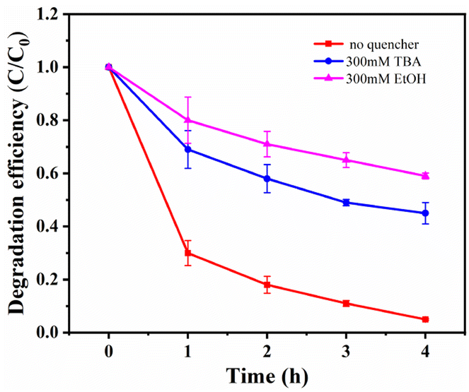
Free radical scavenging experiments and effect of metal ion leaching rate. To investigate the catalytic mechanism and identify the active species in the MnCo2O4/rGO/PS system, quenching experiments were performed by adding various radical scavengers. As reported in previous studies, ·SO4− and OH· are critical for most transition metal activated PS systems.17,39,40 Ethanol (EtOH) was selected for ·SO4− scavenging, and tert-butanol (TBA) was chosen for OH· quenching. As depicted in Fig. 8, the removal efficiency of TCE was significantly reduced from 95% to 44.1% and 58.8% when 300 mM EtOH and 300 mM TBA were added to the TCE solution, confirming that ·SO4− and OH· are the primary active species in the system. To ensure that the material does not cause secondary pollution to the environment, the leaching of metal ions into the solution was tested using ICP-MS. After adding 0.3 g L−1 of the catalyst for 4 h, the concentration of cobalt ion in the solution was 0.211 mg L−1, and the concentration of manganese ion was 0.273 mg L−1, meeting China's industrial pollutant emission standards. Under the same conditions with the MnCo2O4 catalyst, the concentration of cobalt ion in the solution was about 0.665 mg L−1, and the concentration of manganese ion was 1.000 mg L−1.
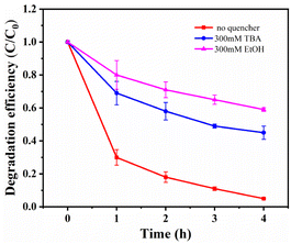 |
| | Fig. 8 Effects of different radical quencher for the TCE degradation in MnCo2O4/rGO/PS system [reaction conditions: PS dosage = 0.3 g L−1, catalyst dosage = 0.3 g L−1, reaction temperature = 25 °C and initial pH value = 6 (unadjusted)]. | |
To investigate the catalytic mechanism and identify the active species in the MnCo2O4/rGO/PS system, quenching experiments were performed by adding various radical scavengers. As reported in previous studies, ·SO4− and OH· are critical for most transition metal activated PS systems.17,39,40 Ethanol (EtOH) was selected for ·SO4− scavenging, and tert-butanol (TBA) was chosen for OH· quenching. As depicted in Fig. 8, the removal efficiency of TCE was significantly reduced from 95% to 44.1% and 58.8% when 300 mM EtOH and 300 mM TBA were added to the TCE solution, confirming that ·SO4− and OH· are the primary active species in the system. To ensure that the material does not cause secondary pollution to the environment, the leaching of metal ions into the solution was tested using ICP-MS. After adding 0.3 g L−1 of the catalyst for 4 h, the concentration of cobalt ion in the solution was 0.211 mg L−1, and the concentration of manganese ion was 0.273 mg L−1, meeting China's industrial pollutant emission standards. Under the same conditions with the MnCo2O4 catalyst, the concentration of cobalt ion in the solution was about 0.665 mg L−1, and the concentration of manganese ion was 1.000 mg L−1, confirming that rGO can serve as a carrier to reduce the overflow of metal ions in the catalyst. These results demonstrate that the leaching of metal ions during the reaction has a negligible impact on the reaction.
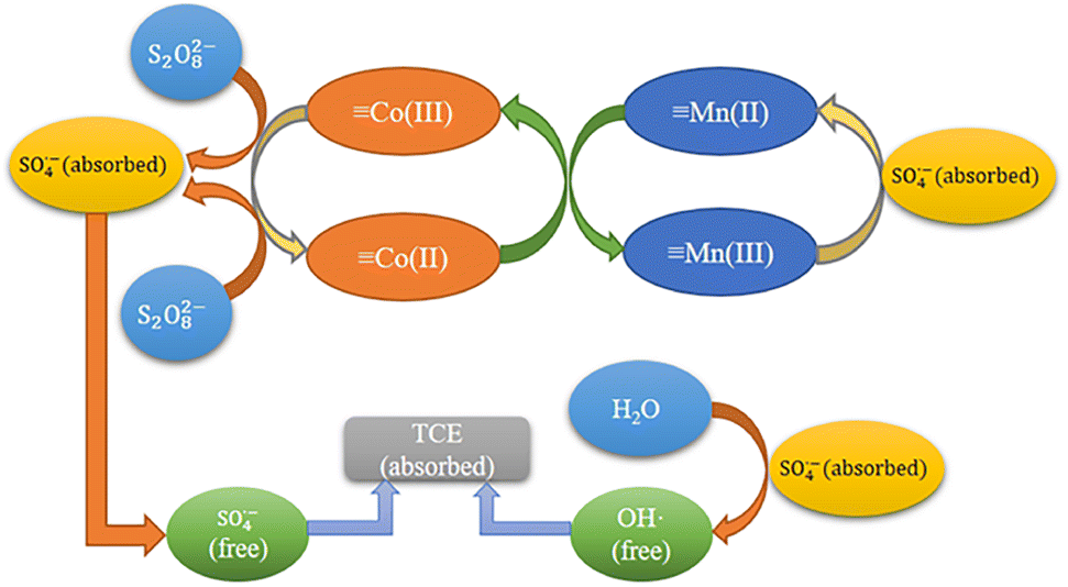
Reaction mechanisms. Based on the previous XPS analysis and free radical scavenging experiments, the possible catalytic process for the degradation of TCE by MnCo2O4/rGO/PS system was proposed. As shown in Fig. 9, this process consists of two parts: surface adsorption and free radical generation reaction. Firstly, MnCo2O4/rGO and PS are added to TCE solution to adsorb pollutants on rGO through interface effect, which is conducive to subsequent electron transfer. At the same time, Mn2+ and Co3+ on the surface of the catalyst will combine with PS to form ·SO4−, and part of ·SO4− will react with H2O to form OH·, which will further participate in the degradation process. These two free radicals will further participate in the degradation process. At the same time, part of the Mn3+ generated during the reaction will be reduced to Mn2+ by ·SO4−, and the other part will continue to react with the Co2+ generated by the reaction to form Mn2+ and Co3+. This equilibrium will continue until PS is exhausted, as shown in eqn (7)–(11).41,42 Furthermore, the synergistic effect of charge transfers between Co2+/Co3+ and Mn2+/Mn3+ redox pairs in MnCo2O4 can also accelerate the electron transfer efficiency, improve the activation efficiency, and promote the generation of free radicals. The standard oxidation–reduction potential of Co3+/Co2+ was 1.92 V, while that of Mn3+/Mn2+ was 1.51 V, which corroborated that the reduction of Co3+ by Mn2+ was thermodynamically feasible (eqn (12)).| | |
Mn2+ + S2O82− → Mn3+ + ·SO4− + SO42−
| (7) |
| | |
Co2+ + S2O82− → Co3+ + ·SO4− + SO42−
| (8) |
| | |
H2O + SO4˙− → H+ + OH· + SO42−
| (9) |
| | |
·SO4− (absorbed) → ·SO4− (free)
| (10) |
| | |
Mn3+ + SO4˙− → Mn2+ + SO42−
| (11) |
| | |
Co3+ + Mn2+ → Co2+ + Mn3+
| (12) |
 |
| | Fig. 9 Reaction mechanism of MnCo2O4/rGO activated PS. | |
To gain deeper insights into the correlation between the properties of the synthesized MnCo2O4/RGO composites and their catalytic activities, we conducted first-principles simulations to investigate the interface between CoMn2O4 and rGO. Detailed information regarding the calculations can be found in the experimental section. Typically, when two materials come into contact, a Schottky electric field arises due to their disparate work functions.43 In our study, the calculated work functions of MnCo2O4 (311) and rGO were determined to be 5.487 eV and 4.456 eV, respectively (Fig. S1†). This discrepancy implies that free electrons will migrate from rGO to MnCo2O4 at the interface until the Fermi levels align (Fig. S2†). As a result, MnCo2O4 acquires a negative charge in equilibrium, while rGO exhibits a positive charge near its surface owing to the injection of electrons from rGO into MnCo2O4. Furthermore, the electric field between MnCo2O4 and rGO remains unscreened due to the low carrier density in the MnCo2O4 semiconductor. Consequently, an accumulation of free electrons occurs near the surface of MnCo2O4. This observation is also supported by the charge density difference at the MnCo2O4 (311)/rGO interface. As illustrated in Fig. S3,† a discernible increase in electron density (depicted by the green color) is observed at the MnCo2O4 surface, while a decrease in electron density is observed at the rGO surface (depicted by the blue color). Consequently, the abundant electrons in MnCo2O4 facilitate the activation of persulfate through the Co(III)/Co(II) and Mn(III)/Mn(II) redox cycles, which in turn provided electrons for PS to break the O–O bond in its molecule, generating SO4˙− species. Notably, the built-in electric field electron transfer from rGo to MnCo2O4 promoted the reduction of Co(III) and Mn(III) and ensured the continuous production of SO4˙−.
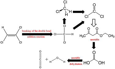
Possible degradation pathways of TCE. The reaction intermediates of TCE degradation were identified by GC-MS (Fig. S4†). The retention time of the intermediates is 8.17 min. Compared with the standard spectrogram, the intermediate product is dichloromethane (CH2Cl2), and a small amount of ethyl acetoacetate (C6H10O3) is generated. It can be inferred from the report that the degradation path of TCE may be to break the double bond through addition reaction to generate chloroform (CHCl3), then dechlorinate to form dichloromethane (CH2Cl2),44 and finally mineralize to H2O and CO2.45,46 The degradation path is shown in Fig. 10.
 |
| | Fig. 10 Possible degradation pathways of TCE. | |
Conclusions
In summary, MnCo2O4/rGO nanocomposites were prepared by two-step solvothermal method and it was then used as catalyst to activate PS toward the degradation of TCE. The effects of different rGO loads on degradation efficiency were discussed. Compared with bare MnCo2O4, MnCo2O4/rGO composite was more stable and has stronger activation performance for PS. The degradation efficiency of trichloroethylene can reach 95% within 4 h without changing the initial pH value. The leaching rate of metal ions after the reaction suggests that the leaching of metal ions during the reaction process has little impact on the environment. The explanation mechanism in the reaction process was studied by XPS analysis and free radical scavenging experiment, and it was proved that ·SO4− and OH· were both present and active. In addition, the degradation path of TCE was verified by GC/MS. The results showed that the degradation path was a bond breaking dechlorination process, with dichloromethane (CH2Cl2) and a small amount of ethyl acetoacetate (C6H10O3) as its intermediate products, and finally mineralized into H2O and CO2. All the results show that MnCo2O4/rGO nanocomposite is an efficient catalyst and can be widely used in the degradation of pollutants in the environment.
Author contributions
All authors contributed to the study conception and design. Material preparation, data collection and analysis were performed by Lu Zhang, Pengfei Ji, Rui Song, Jiayuan Li, Kaifeng Qin and Gang Xu. The first draft of the manuscript was written by Lu Zhang and all authors commented on previous versions of the manuscript. All authors read and approved the final manuscript.
Conflicts of interest
There are no conflicts to declare.
Acknowledgements
We thank all participants for their cooperation and support. We are grateful for the technical support provided by the School of Environmental and Chemical Engineering of Shanghai University. This work was supported by the National Natural Science Foundation of China (No. 11975147 and 12175133), and National Key Research and Development Project (No. 2021YFC1808902, 2020YFC1808203).
References
- K. Ohlen, Y. K. Chang, W. Hegemann, C. R. Yin and S. T. Lee, Chemosphere, 2005, 58, 373–377 CrossRef CAS PubMed.
- B. Bakke, P. A. Stewart and M. A. Waters, J. Occup. Environ. Hyg., 2007, 4, 375–390 CrossRef CAS PubMed.
- K. M. Gilbert, B. Przybyla, N. R. Pumford, T. Han, J. Fuscoe, L. K. Schnackenberg, R. D. Holland, J. C. Doss, L. A. MacMillan-Crow and S. J. Blossom, Chem. Res. Toxicol., 2009, 22, 626–632 Search PubMed.
- T. Alapi and A. Dombi, Chemosphere, 2007, 67, 693–701 CrossRef CAS PubMed.
- S. D. Justicia-Leon, S. Higgins, E. E. Mack, D. R. Griffiths, S. Q. Tang, E. A. Edwards and F. E. Loffler, Environ. Sci. Technol., 2014, 48, 1851–1858 CrossRef CAS PubMed.
- B. Z. Li, K. F. Lin, W. Zhang, S. G. Lu and Y. D. Liu, J. Environ. Eng., 2012, 138, 903–914 CrossRef CAS.
- S. Randazzo, O. Scialdone, E. Brillas and I. Sires, J. Hazard. Mater., 2011, 192, 1555–1564 CrossRef CAS PubMed.
- Z. S. Wei and Y. Seo, J. Hazard. Mater., 2010, 181, 147–153 CrossRef CAS PubMed.
- J. S. Yang, K. Baek, T. S. Kwon and J. W. Yang, J. Ind. Eng. Chem., 2009, 15, 777–779 CrossRef CAS.
- Y. Miyake, A. Sakoda, H. Yamanashi, H. Kaneda and M. Suzuki, Water Res., 2003, 37, 1852–1858 CrossRef CAS.
- F. Berrelleza-Valdez, J. Parades-Aguilar, C. E. Pena-Limon, M. T. Certucha-Barragan, N. Gamez-Meza, D. Serrano-Palacios, L. A. Medina-Juarez and K. Calderon, J. Environ. Manage., 2019, 241, 211–218 CrossRef CAS PubMed.
- A. Siggins, A. M. Enright and V. O'Flaherty, Water Res., 2011, 45, 4035–4046 CrossRef CAS PubMed.
- M. Ahmad, S. S. Lee, A. U. Rajapaksha, M. Vithanage, M. Zhang, J. S. Cho, S. E. Lee and Y. S. Ok, Bioresour. Technol., 2013, 143, 615–622 CrossRef CAS PubMed.
- W. S. Koe, J. W. Lee, W. C. Chong, Y. L. Pang and L. C. Sim, Environ. Sci. Pollut. Res., 2020, 27, 2522–2565 CrossRef CAS PubMed.
- A. Baldermann, S. Kaufhold, R. Dohrmann, C. Baldermann, I. Letofsky-Papst and M. Dietzel, Chemosphere, 2021, 282, 131018 CrossRef CAS PubMed.
- M. Priyadarshini, I. Das, M. M. Ghangrekar and L. Blaney, J. Environ. Manage., 2022, 316, 115295 CrossRef CAS PubMed.
- S. Waclawek, H. V. Lutze, K. Grubel, V. V. T. Padil, M. Cernik and D. D. Dionysiou, Chem. Eng. J., 2017, 330, 44–62 CrossRef CAS.
- P. Hu and M. Long, Appl. Catal., B, 2016, 181, 103–117 CrossRef CAS.
- Y. F. Ji, W. P. Xie, Y. Fan, Y. Y. Shi, D. Y. Kong and J. H. Lu, Chem. Eng. J., 2016, 286, 16–24 CrossRef CAS.
- R. L. Johnson, P. G. Tratnyek and R. O. Johnson, Environ. Sci. Technol., 2008, 42, 9350–9356 CrossRef CAS.
- A. Ghauch, A. M. Tuqan and N. Kibbi, Chem. Eng. J., 2012, 197, 483–492 CrossRef CAS.
- R. C. Zhang, P. Z. Sun, T. H. Boyer, L. Zhao and C. H. Huang, Environ. Sci. Technol., 2015, 49, 3056–3066 CrossRef CAS PubMed.
- W. S. Chen and Y. C. Su, Ultrason. Sonochem., 2012, 19, 921–927 CrossRef CAS.
- J. Criquet and N. K. V. Leitner, Chem. Eng. J., 2011, 169, 258–262 CrossRef CAS.
- Y. Lei, C. S. Chen, Y. J. Tu, Y. H. Huang and H. Zhang, Environ. Sci. Technol., 2015, 49, 6838–6845 CrossRef CAS PubMed.
- Y. B. Ding, L. H. Zhu, N. Wang and H. Q. Tang, Appl. Catal., B, 2013, 129, 153–162 CrossRef CAS.
- G. P. Anipsitakis and D. D. Dionysiou, Environ. Sci. Technol., 2003, 37, 4790–4797 CrossRef CAS PubMed.
- J. Fernandez, P. Maruthamuthu, A. Renken and J. Kiwi, Appl. Catal., B, 2004, 49, 207–215 CrossRef CAS.
- X. Y. Chen, J. W. Chen, X. L. Qiao, D. G. Wang and X. Y. Cai, Appl. Catal., B, 2008, 80, 116–121 CrossRef CAS.
- S. Muhammad, E. Saputra, H. Q. Sun, J. D. Izidoro, D. A. Fungaro, H. M. Ang, M. O. Tade and S. B. Wang, RSC Adv., 2012, 2, 5645–5650 RSC.
- G. S. Wang, Y. Y. Ma, Y. Tong and X. F. Dong, J. Ind. Eng. Chem., 2017, 48, 142–150 CrossRef CAS.
- T. Zhu, S. C. Chang, Y. F. Song, M. Lahoubi and W. Wang, Chem. Eng. J., 2019, 373, 755–766 CrossRef CAS.
- G. Jayalakshmi, K. Saravanan, T. Arun, K. Suresh, B. Sundaravel, B. K. Panigrahi and D. Kanjilal, Carbon, 2017, 119, 172–178 CrossRef CAS.
- P. L. Meena, S. Pal, K. Sreenivas and R. Kumar, Adv. Sci. Lett., 2015, 21, 2760–2763 CrossRef.
- Y. J. Yao, Z. H. Yang, D. W. Zhang, W. C. Peng, H. Q. Sun and S. B. Wang, Ind. Eng. Chem. Res., 2012, 51, 6044–6051 CrossRef CAS.
- P. L. Hao, M. Z. Hu, R. Xing and W. J. Zhou, J. Alloys Compd., 2020, 823, 153757 CrossRef CAS.
- X. Y. Wang, J. J. Jiang, Y. H. Ma, Y. Y. Song, T. R. Li and S. S. Dong, J. Colloid Interface Sci., 2021, 600, 449–462 CrossRef CAS PubMed.
- N. H. Trang, E. Kwon, G. Lisak, C. Hu and K. Y. A. Lin, Chemosphere, 2021, 267, 128906 CrossRef CAS PubMed.
- Z. Zhou, X. Liu, K. Sun, C. Lin, J. Ma, M. He and W. Ouyang, Chem. Eng. J., 2019, 372, 836–851 CrossRef CAS.
- S. Wacławek, H. V. Lutze, K. Grübel, V. V. T. Padil, M. Černík and D. D. Dionysiou, Chem. Eng. J., 2017, 330, 44–62 CrossRef.
- Q. Z. Ni, J. F. Ma, C. H. Fan, Y. Kong, M. G. Peng and S. Komarneni, Ceram. Int., 2018, 44, 19474–19480 CrossRef CAS.
- J. Deng, Y. Q. Cheng, Y. A. Lu, J. C. Crittenden, S. Q. Zhou, N. Y. Gao and J. Li, Chem. Eng. J., 2017, 330, 505–517 CrossRef CAS.
- C. Zhang, X. P. Geng, S. L. Tang, M. S. Deng and Y. W. Du, J. Mater. Chem. A, 2017, 5, 5912–5919 RSC.
- H. R. Dong, K. J. Hou, W. W. Qiao, Y. J. Cheng, L. H. Zhang, B. Wang, L. Li, Y. Y. Wang, Q. Ning and G. M. Zeng, Chem. Eng. J., 2019, 359, 1046–1055 CrossRef CAS.
- T. Chang, C. L. Ma, A. Nikiforov, S. K. P. Veerapandian, N. De Geyter and R. Morent, J. Phys. D: Appl. Phys., 2022, 55, 125202 CrossRef CAS.
- M. Ali, M. Danish, M. Tariq, A. Ahmad, K. S. Ayub and S. G. Lyu, Chem. Eng. J., 2020, 399, 125754 CrossRef CAS.
|
| This journal is © The Royal Society of Chemistry 2023 |
Click here to see how this site uses Cookies. View our privacy policy here. 
 Open Access Article
 This Open Access Article is licensed under a Creative Commons Attribution-Non Commercial 3.0 Unported Licence
 *ab
*ab