 Open Access Article
Activating biomass carbon with metallurgical slag by pyrolysis in molten salt for high-performance supercapacitors
Teng Lv a,
Jun Lia,
Yong Shia,
Huan Yub and
Jing Chen*a
aWuhan Wuchang District Ecological Environment Monitoring Station, Wuhan 430061, People's Republic of China. E-mail: 459544759@qq.com
bSchool of Environmental Studies, China University of Geosciences, Wuhan 430074, People's Republic of China
First published on 31st July 2023
Abstract
Pyrolysis of sustainable biomass to advanced carbon materials for energy storage is key-enabling in energy and environmental sustainability. However, obtaining carbon materials with well-defined microstructure and composition for high-performance energy storage is extremely challenging. Herein, efficient activation of biomass carbon is realized by introducing extra metallurgical slag during pyrolysis of coconut shell in Na2CO3–K2CO3 molten salt. The molten salt guides the formation of carbon with a hierarchical honeycomb-like nanostructure, while the metallurgical slag facilitates enhanced doping of the heteroatom species, conjointly contributing to the increase of the specific surface area of carbon materials from 424 m2 g−1 to 1451 m2 g−1 and the extension of the single N dopant to multiple dopants of N, P, Zn and Co. Such adequate tuning of the microstructure and composition in the pyrolysis product increases the capacitance for supercapacitors from 30 F g−1 to 135 F g−1 at 0.5 A g−1. The results can provide new insights for the controllable upgradation of both biomass and waste industrial slag toward enhanced energy storage.
1. Introduction
Both the nonrenewable feature and greenhouse gas emissions of the traditional fossil fuels are pressurizing the society to develop sustainable energy supplies worldwide.1–4 However, the most promising sustainable energies such as solar, wind, and hydro energy are highly intermittent, which means that storing the generated electricity from these fluctuating energies is in great need for promising a steady energy supply.5–7The supercapacitor is one of the bright electrochemical energy-storage devices,8–10 promising advantages in safety and long cycling stability over batteries. Specifically, supercapacitors present a dendrite-free and negligible heat-generation working mode and are therefore almost free of safety problems.11–13 Moreover, the cycling life of supercapacitors is generally up to 100![[thin space (1/6-em)]](https://www.rsc.org/images/entities/char_2009.gif) 000 cycles, which greatly exceeds that of the most advanced batteries (<10
000 cycles, which greatly exceeds that of the most advanced batteries (<10![[thin space (1/6-em)]](https://www.rsc.org/images/entities/char_2009.gif) 000 cycles).11,14 Hence, supercapacitors provide attractive prospects, especially in areas needing fast charging and great cycling stability. However, the energy density of supercapacitors (∼5 W h kg−1) is much lower than that of batteries (up to 200 W h kg−1).11,13,15 Increasing the energy density of supercapacitors is urgently needed.
000 cycles).11,14 Hence, supercapacitors provide attractive prospects, especially in areas needing fast charging and great cycling stability. However, the energy density of supercapacitors (∼5 W h kg−1) is much lower than that of batteries (up to 200 W h kg−1).11,13,15 Increasing the energy density of supercapacitors is urgently needed.
Carbon materials are widely used as electrode materials for supercapacitors, and the structure–composition design is crucial for improving its performances.11 The capacitance of supercapacitors originates from interfacial reactions on electrode materials. Thus, the high specific surface area of carbon materials with hierarchical porous structures can provide more reaction sites and superior reaction kinetics.11,16,17 In addition, doping the carbon materials with heteroatoms to tune the electronic structure and induce pseudocapacitance is another strategy for enhancing the performance.18
Biomass-derived carbon is a carbon-based material that is widely applied in various fields, such as catalysts, adsorbents, and electrodes.19–22 Coconut shell is a promising carbon source for biomass-derived carbon due to its availability, high carbon content, excellent adsorption ability and environmental safety.23–27 Compared with traditional unsustainable carbon resources, the biomass-derived carbon materials by pyrolysis promise the following appealing advantages: (1) being a sustainable resource. Biomass is the product of photosynthesis, thus being sustainable and environmentally friendly;7 (2) easy realization of heteroatom doping. The biomass commonly contains nitrogen (N) and phosphorus (P) elements. Therefore, the uniform self-doping of heteroatoms can be realized;16,17 (3) organic matter can facilitate the generation of a porous structure. Pyrolysis of organic matter in biomass can release gaseous products, acting as foaming agents for generating porous structures.28 Despite the above merits, obtaining a porous architecture from biomass is not easy due to the structure collapse during the high-temperature pyrolysis process.29,30 Moreover, the N/P elements are easily lost as gaseous products, leading to the insufficient doping of nonmetallic elements.7,28 Converting biomass into a porous structure with a well-defined structure and composition in a green and facile large-scale synthesis way for high-performance supercapacitors is still very challenging.
Pyrolysis of biomass in molten salts has attracted increasing interest in recent years due to its many fascinating merits.7,28 Compared with pyrolysis in a gaseous atmosphere, molten salts can slow down the release of gaseous product, contributing to a more efficient pore-forming process.3,16,28 Moreover, the molten salts can act as templates, also facilitating the generation of a porous structure.31,32 The strong ability of the molten salt for dissolving metallic salts and nonmetallic oxides can achieve the smooth and homogeneous doping reactions of heteroatoms.3,30 The high-temperature molten salts can also enable the pyrolysis of biomass in a liquid media, which can retard the escape of N/P-containing species, promoting the doping of N/P elements.16,31
In addition to non-metallic elements, doping metallic elements can increase the capacitance of carbon materials for supercapacitors.6,10,11,33 However, the biomass contains negligible metallic elements, greatly limiting the further capacitance enhancement of biomass carbon for the supercapacitor.7 On the other hand, metallurgical slags commonly contain many useless metallic elements.34 Even worse, the entrainment of heavy metals turns these slags into hazardous wastes, making the disposal of the metallurgical slags very difficult in some cases.35 For example, during the zinc smelting process, the purification of zinc sulfate solution results in slags containing zinc (Zn) and cobalt (Co) elements, which are typical hazardous wastes.34,35 Introducing these metallic elements in slags into the biomass-derived carbon can hopefully upgrade the carbonaceous materials, and facilitate the disposal of hazardous slags.
Herein, activating the biomass (coconut shell)-derived carbon with metallurgical slag for application in supercapacitors is realized by pyrolysis in molten salts. Specifically, by tuning the molten salt composition, N/P co-doped carbon materials with a well-defined porous structure can be obtained, greatly increasing the specific surface areas. Further addition of the zinc-smelting slags into the molten salts during pyrolysis can introduce the metallic elements of both Zn and Co in the slag into the biomass-derived carbon as metallic dopants. Moreover, the pyrolysis of biomass in the slag-containing molten salt can contribute to the more efficient doping of phosphorus atoms. Resultantly, the performances of coconut shell-derived biomass carbon are greatly enhanced. Moreover, molten carbonates possess good stability and mild properties, which will enable long-term durability for usage and not pose a threat to the environment.36 Molten carbonates can provide excellent heat transfer during biomass pyrolysis because of the fluidic heat storage ability.27 The results in this paper can provide new insights for both preparing high-performance carbon materials for supercapacitors and the disposal of hazardous slags. Hopefully, the proposed strategy can be extended from coconut shell and zinc-smelting slag to other kinds of biomass and waste slags.
2. Experimental
2.1 Materials synthesis
All reagents are of analytical purity. The metallurgical slag was provided by a zinc-smelting plant, and the composition of the zinc-smelting slag was characterized and is shown in Table 1. The salt (KCl, NaCl, Na2CO3, and K2CO3) was weighed according to the pre-determined amount, and then dried at 300 °C for more than 12 h to remove the moisture. For the NaCl–KCl molten salt, the molar ratio of NaCl and KCl was fixed to be 1![[thin space (1/6-em)]](https://www.rsc.org/images/entities/char_2009.gif) :
:![[thin space (1/6-em)]](https://www.rsc.org/images/entities/char_2009.gif) 1. The molar ratio of Na2CO3 and K2CO3 was fixed to be 1
1. The molar ratio of Na2CO3 and K2CO3 was fixed to be 1![[thin space (1/6-em)]](https://www.rsc.org/images/entities/char_2009.gif) :
:![[thin space (1/6-em)]](https://www.rsc.org/images/entities/char_2009.gif) 1. The coconut shell was crushed and the resulting powders were fully mixed with the weighed salts, fixing the mass ratio between the coconut shell powder and molten salts to be 1
1. The coconut shell was crushed and the resulting powders were fully mixed with the weighed salts, fixing the mass ratio between the coconut shell powder and molten salts to be 1![[thin space (1/6-em)]](https://www.rsc.org/images/entities/char_2009.gif) :
:![[thin space (1/6-em)]](https://www.rsc.org/images/entities/char_2009.gif) 4. Then, the mixture was heated to 800 °C for a continuous pyrolysis of 2 h. The entire pyrolysis process was conducted in an inert atmosphere provided by an argon gas flow (200 mL min−1). In another experiment, 2% metallurgical slag was added into the Na2CO3–K2CO3 molten salts for pyrolysis of the coconut shell powder. For comparison, pyrolysis in the inert gas without molten salts was also conducted. After pyrolysis, all samples were firstly rinsed in high-purity water at 80 °C to remove the salts for recycling usage. Then, the resulting powders were further leached in the diluted hydrochloric acid to thoroughly remove the entrapped salts and oxides. Finally, the products were dried at 60 °C for more than 24 h for use.
4. Then, the mixture was heated to 800 °C for a continuous pyrolysis of 2 h. The entire pyrolysis process was conducted in an inert atmosphere provided by an argon gas flow (200 mL min−1). In another experiment, 2% metallurgical slag was added into the Na2CO3–K2CO3 molten salts for pyrolysis of the coconut shell powder. For comparison, pyrolysis in the inert gas without molten salts was also conducted. After pyrolysis, all samples were firstly rinsed in high-purity water at 80 °C to remove the salts for recycling usage. Then, the resulting powders were further leached in the diluted hydrochloric acid to thoroughly remove the entrapped salts and oxides. Finally, the products were dried at 60 °C for more than 24 h for use.
| ZnO | Co3O4 | PbO | SiO2 | CaO | Al2O3 | FeO | Others |
|---|---|---|---|---|---|---|---|
| 3.9 | 0.7 | 0.4 | 28 | 13 | 7 | 42.4 | 4.6 |
2.2 Characterizations
The crystalline structures of the as-obtained powders were characterized by X-ray diffraction (XRD) using a PANalytical X'Pert Pro X-ray diffractometer with Ni filtered Cu Kα radiation (λ = 1.5406 Å). X-ray photoelectron spectroscopy (XPS) was performed on a VG ESCALAB210 apparatus with Mg Kα source. The C 1s as a reference signal was adjusted to 284.8 eV. Field-emission scanning electron microscopy (FESEM, Zeiss SIGMA) was adopted to understand the morphology differences of various samples. Nitrogen adsorption–desorption measurements were performed, using a NOVA 4200e instrument at 77 K.2.3 Electrochemical measurements
The obtained products, binder (polytetrafluoroethylene, PTFE), and conducting agent (super P) were well mixed by adding several drops of ethanol, with the mass ratio being 8![[thin space (1/6-em)]](https://www.rsc.org/images/entities/char_2009.gif) :
:![[thin space (1/6-em)]](https://www.rsc.org/images/entities/char_2009.gif) 1
1![[thin space (1/6-em)]](https://www.rsc.org/images/entities/char_2009.gif) :
:![[thin space (1/6-em)]](https://www.rsc.org/images/entities/char_2009.gif) 1. Then, the slurry was rolled into a film and dried at 120 °C in vacuum overnight. The electrochemical performances of all samples were conducted in a three-electrode system, with a saturated calomel electrode and graphite rod being used as the reference electrode and counter electrode, respectively. For the preparation of the working electrode, the as-prepared slurry film was cut into a size of 1 cm × 1 cm and then coated onto a titanium mesh by die-pressing. All electrochemical tests were conducted in 2 M KOH solution using a CHI 1140C electrochemical working station, with the cyclic voltammogram curves (CV) and galvanostatic charge/discharge (GCD) tests being acquired for evaluating the performances according to the following formulas:
1. Then, the slurry was rolled into a film and dried at 120 °C in vacuum overnight. The electrochemical performances of all samples were conducted in a three-electrode system, with a saturated calomel electrode and graphite rod being used as the reference electrode and counter electrode, respectively. For the preparation of the working electrode, the as-prepared slurry film was cut into a size of 1 cm × 1 cm and then coated onto a titanium mesh by die-pressing. All electrochemical tests were conducted in 2 M KOH solution using a CHI 1140C electrochemical working station, with the cyclic voltammogram curves (CV) and galvanostatic charge/discharge (GCD) tests being acquired for evaluating the performances according to the following formulas:
 | (1) |
 | (2) |
 | (3) |
2.4 DFT calculations
The density-functional-theory (DFT) calculations were performed by using the Vienna Ab initio Simulation Package (VASP) with Projector Augmented Wave (PAW) method.1,2 The Perdew–Burke–Ernzerhof (PBE) functional for the exchange–correlation term was used with the projector-augmented wave method, with the kinetic energy cutoff of the electron wavefunctions being set as 450 eV. The convergence of energy and forces were set to be 1 × 10⁻⁴ eV and 0.05 eV Å−1, respectively. The adsorption energy and charge density of the K atom on the graphite (002) plane doped with various heteroatoms were determined to understand the performance enhancement mechanism. The adsorption energy is defined as: Eads = E(K/surf) − E(surf) − E(K), where E(K/surf), E(surf) and E(K) are the calculated total energies of the substrate with the K atom, the bare graphite (002) substrate without/containing heteroatoms, and the isolated K atom, respectively.2,303. Results and discussions
3.1 Morphology optimizations
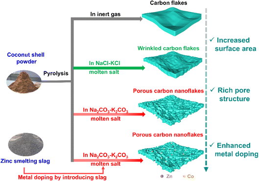
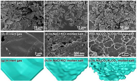
Pyrolysis of coconut shell was conducted under four different conditions, as shown in Fig. 1, namely in an inert atmosphere, in NaCl–KCl molten salt, in Na2CO3–K2CO3 molten salt, and in 2% slag-added Na2CO3–K2CO3 molten salt. Pyrolysis in inert gas resulted in carbon flakes with smooth surfaces. When the pyrolysis atmosphere was changed to NaCl–KCl molten salt, the smooth surfaces of the carbon flake products became wrinkled. More interestingly, a highly well-defined porous structure was obtained by replacing the NaCl–KCl molten salt with Na2CO3–K2CO3 molten salt. Introducing the zinc-smelting slag into the molten salts can hopefully induce metal into the carbon products, but poses a negligible influence on the morphology of the products.The SEM results in Fig. 2 manifest the abovementioned illustrations for the morphology differences of various samples. As shown in Fig. 2a and d, the pyrolysis products in the inert gas consist of very large flakes (Fig. 2a), presenting a very smooth surface (Fig. 2d, as illustrated in Fig. 2g). The results indicate that the released gaseous products from the pyrolysis of the organic mass in the coconut shell escape from the reaction sites very swiftly,16,28 exerting a negligible influence on the surface morphology of the pyrolysis products. When the NaCl–KCl molten salt is employed, the carbon flakes in the pyrolysis products were partially fractured (Fig. 2b), with the surface turning from smooth textures to wrinkled architectures (Fig. 2e and h). The morphology variation implies that the escape process of the pyrolysis gases was retarded, striking the newly generated carbon flake surfaces into wrinkled pits.
The pyrolysis products with the most appealing morphology were obtained in the Na2CO3–K2CO3 molten salt, showing honeycomb-like porous structures. As shown in Fig. 2c, almost all of the bulk carbon flakes were cracked into small particles. Closer observation of the particle points to a highly porous architecture (Fig. 2f, as illustrated in Fig. 2i). The results indicate that the microenvironment for coconut shell pyrolysis is greatly changed in the Na2CO3–K2CO3 molten salt, leading to pyrolysis products with totally different microstructures. Such a huge discrepancy is possibly caused by the following reasons: (1) a high ability for trapping gaseous products. Compared with the NaCl–KCl molten salt, alkaline oxides such as Na2O and K2O exist in the Na2CO3–K2CO3 molten salt,7,37 which can absorb the acid gases of NOx and PxOy, buffering the escape of these pyrolysis-generated gases and contributing to more pores in the final products;38 (2) a bubbling effect was triggered by the pyrolysis of the coconut shell. The reaction equilibriums for CO32− decomposition (Na2CO3 ⇌ Na2O + CO2; K2CO3 ⇌ K2O + CO2) exist in molten carbonates.37 Once pyrolysis of organic mass occurs, CO2 can be depleted by the released NOx or PxOy, which can lead to the accelerated decomposition of carbonates within the pyrolysis microenvironment, causing a bubbling effect for generating more pores in the pyrolysis products;29,37,39 (3) fracture of carbon flakes results in many opening holes for penetration of molten salt, facilitating the molten salts to act as templates for creating more pores in the products.31
In a word, carbon materials with well-defined porous structures can be obtained from the coconut shell by pyrolysis in the Na2CO3–K2CO3 molten salt. It should be mentioned that adding the zinc-smelting slag into the carbonate molten salt has a negligible effect on the morphology of the products, but hopefully can modify the composition.
3.2 Pore structures and composition comparisons
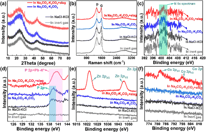
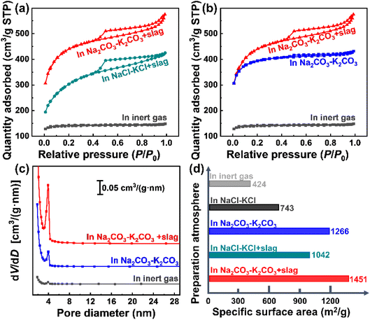
The addition of zinc-smelting slag has a negligible influence on the morphology of coconut shell-derived carbon materials. However, it can greatly affect the composition of the products (Fig. 3). Both the XRD patterns (Fig. 3a) and Raman spectra (Fig. 3b) point to the peaks of graphite, meaning that all of the pyrolysis products present a graphitic structure. The broad peak in the XRD pattern means that the products are partially graphitic. No impurity peaks are observed in Fig. 3a and b, implying a relative high purity of the graphitic products. The results agree with reported results.16,31 XPS spectra were obtained to investigate the composition differences, and are presented in Fig. 3c–f. The N 1s spectrum shows a negligible discrepancy for all four different samples presented in Fig. 3c, indicating that both the molten salts and the added slag have very little influence on the process of nitrogen doping. However, as shown in Fig. 3d, the spectrum presents huge differences for various samples. Specifically, the phosphorus in the coconut shell is hardly doped into the derived carbon product when pyrolysis occurs in the inert gas. However, peaks related to P 2p are observed in the pyrolysis products obtained in both NaCl–KCl molten salt and Na2CO3–K2CO3 molten salt, meaning that the molten salt facilitates the doping of phosphorus. After the addition of metallurgical slag into the Na2CO3–K2CO3 molten salt, a peak appears at around 138–142 eV, which is attributed to the superposition of P 2p and Pb 4f. Phosphorous (P) is one of the most important nutrient elements for plants, while lead (Pb) is present in metallurgical slag (Table 1). The binding energies of P 2p and Pb 4f are very close.40,41 As shown in Fig. 3d, adding metallurgical slag results in an obvious shift of the peak towards higher binding energy because the introduced Pb element in slag possesses slightly higher binding energy than P. In addition, the peak intensity is increased because of the superposition of the slag-introduced Pb 4f signal and biomass-generated P 2p peak. Moreover, the Zn and Co elements are effectively doped into the pyrolysis products, as shown in Fig. 3e and f. The results verify that both the molten salt media and the additives of zinc smelting slag can tune the surface compositions, and increase the species and contents of doped heteroatoms in the derived pyrolysis products.The pore distributions and specific surface areas in Fig. 4 exhibit huge discrepancies between different samples. As shown in Fig. 4a, pyrolysis in molten salts contributes to carbon materials with higher surface areas than that in inert gas. Likewise, the product obtained in the Na2CO3–K2CO3 molten salt possesses a higher surface area than that in the NaCl–KCl molten salt (Fig. 4a), again demonstrating that the molten salt composition can affect the pyrolysis process. Fig. 4b shows that the specific surface area of the pyrolysis product is increased after adding the slag. More importantly, the hysteresis loop appears only after adding the zinc-smelting slag (Fig. 4a and b), meaning that addition of slag facilitates the generation of abundant mesopores in the pyrolysis products. Such results are proved by the pore size distributions in Fig. 4c, which shows that the pore volume follows the order of “Na2CO3–K2CO3 molten salt + slag” > “Na2CO3–K2CO3 molten salt” > “inert gas”. The pore size of all samples is about 4 nm, which is typical of mesopores,31 being favorable for ion diffusion and electrolyte penetration.42,43 The specific surface areas in Fig. 4d show that the product obtained in “Na2CO3–K2CO3 molten salt + slag” presents the highest specific surface area of 1451 m2 g−1, which is much higher than the 1266 m2 g−1 in “Na2CO3–K2CO3 molten salt”, 1042 m2 g−1 in “NaCl–KCl molten salt + slag”, 743 m2 g−1 in “NaCl–KCl molten salt”, and 7424 m2 g−1 in “inert gas”. Due to the strong dissolving capacity of the molten salts and the wash procedure of the material synthesis, the coverage of the pyrolysis product by the remaining slag is negligible. The results further prove that the concerted effect of molten salt and slag can conjointly contribute to the pyrolysis product with greatly increased specific surface area and abundant mesopores.
Pyrolysis in molten salt contributes to the additional doping of the coconut-containing phosphorus into the carbon product. Further addition of the zinc-smelting slag can enhance the contents of the doped nonmetallic elements and introduce metallic dopants of Zn and Co into the carbon materials at the same time. In addition, the concerted effect of the molten salt and the zinc-smelting slag can greatly increase the specific surface area and the mesopores in the pyrolysis product. The greater amount of multi-type dopants and increased specific surface area, as well as abundant mesopores in the pyrolysis product, can conjointly contribute to the enhanced performance for supercapacitors.
3.3 Performance tests and enhancing mechanisms
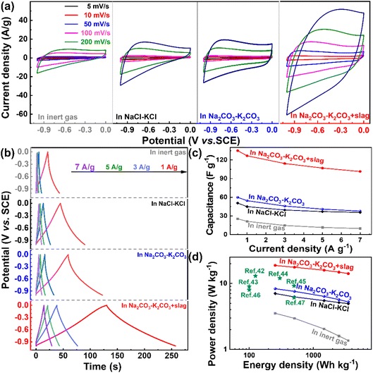
The performances of the as-prepared samples as supercapacitors were evaluated in a three-electrode system (Fig. 5). The CV curves for all samples are rectangular in shape (Fig. 5a), revealing that the electrical double-layer process dominates the capacitance contribution.11,44 However, the shapes for the pyrolysis product in “Na2CO3–K2CO3 molten salt + slag” present much more distorted shapes, suggesting that the capacitive response is attributed to the mixed contribution of the electrical double-layer capacitance and pseudo-capacitance.11,45,46 Such changes are possibly caused by the more abundant nonmetallic and metallic dopants in the pyrolysis product obtained in “Na2CO3–K2CO3 molten salt + slag”. Furthermore, the pyrolysis product obtained by pyrolysis in “Na2CO3–K2CO3 molten salt + slag” exhibits the largest current density (Fig. 5a), which is possibly due to the higher specific surface area for surface reactions and more abundant mesopores for ion diffusion,47 which means a much higher capacitance than the other samples.The appealing reaction kinetics for the pyrolysis product obtained in “Na2CO3–K2CO3 molten salt + slag” are manifested by the galvanostatic charge/discharge results (Fig. 5b) and capacitance comparisons (Fig. 5c), as well as Ragone plots (Fig. 5d). As shown in Fig. 5b, the pyrolysis product obtained in “Na2CO3–K2CO3 molten salt + slag” shows the longest discharge time among all the tested samples (Fig. 5b), corresponding to the highest capacitance (Fig. 5c). The results reveal that the addition of slag is essential for fully activating the pyrolysis product as the supercapacitor materials because the capacitance values are improved greatly at all tested current densities (Fig. 5d). For instance, the capacitances for pyrolysis products obtained in “Na2CO3–K2CO3 molten salt” is only 59.9 F g−1 at 0.5 A g−1, which is greatly increased to 135 F g−1 at 0.5 A g−1 for the product obtained in “Na2CO3–K2CO3 molten salt + slag”. The superior performances of the pyrolysis products obtained in “Na2CO3–K2CO3 molten salt + slag” is substantiated by the highest power densities in the Ragone plots (Fig. 5d), which shows that the best sample possesses an energy density of 18.75 W h kg−1 at a power density of 260 W kg−1, retaining 14.09 W h kg−1 at 3625 W kg−1. The performances of the pyrolysis product obtained in “Na2CO3–K2CO3 molten salt + slag” are superior to those of reported biomass-derived carbon materials (Fig. 5d).42–47 The comparison of the specific capacitance (Cs) for coconut shell-derived carbon and other biomass-derived carbon materials in previous research studies is listed in Table 2.
| Biomass-derived carbon | Cs (F g−1) | Test condition | Electrolyte | References |
|---|---|---|---|---|
| Coconut shell | 135 | 0.5 A g−1 | 6 M KOH | This paper |
| Chestnut shell | 106 | 500 mA cm−2 | 1 M H2SO4 | 49 |
| Leaf of phoenix tree | 106 | |||
| Corn core | 83.3 | |||
| Wormwood | 117.5 | |||
| Corn straw | 127 | |||
| Rice straw | 115 | |||
| Saw dust | 78.5 | |||
| Orange peal | 129.5 | |||
| Sunflower shell | 105.5 | |||
| Pomelo peel | 300 | 0.5 A g−1 | 6 M KOH | 43 |
| Tobacco stem | 144 | 0.2 A g−1 | 6 M KOH | 50 |
| Banana fiber | 74 | 0.5 A g−1 | 1 M Na2SO4 | 51 |
| Pine nut shell | 128 | 0.5 A g−1 | 6 M KOH | 52 |
Although the performance of the coconut shell-derived carbon obtained in “Na2CO3–K2CO3 molten salt + slag” is lower than the biomass-derived carbon in the supercapacitors, e.g., ∼210.2 F g−1 at 5 A g−1 reported by Yin et al.,48 the results herein exhibit a shorter method for preparing biomass carbon by integrating the biomass pyrolysis and biomass-derived carbon activation together with the addition of metallurgical slag. Of note, the usage of the nonferrous metals in metallurgical slag as a doping source for carbon materials is highly desirable in terms of saving strategic metals and cost reduction. Furthermore, anchoring the transition metal oxides or other nonmetallic dopants into the biomass-derived carbon can be further explored to increase the capacitance in the future.
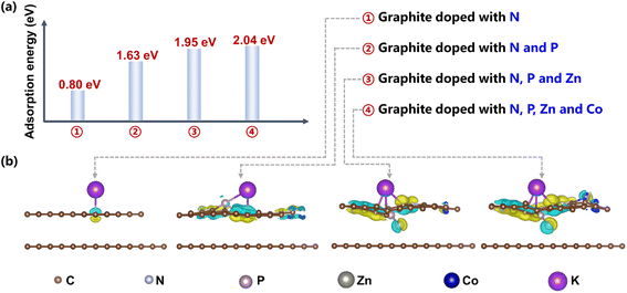
The DFT calculation results reveal that the abundant doping species for pyrolysis products obtained in “Na2CO3–K2CO3 molten salt + slag” contributes to more efficient adsorption of K+ in the electrolyte and induces stronger interfacial electron interactions, which is beneficial for ion storages in supercapacitors. As shown in Fig. 6a, the adsorption energies of K+ on “graphite doped with N” and “graphite co-doped with N and P” are 0.80 eV and 1.63 eV, respectively, implying that the extra doping of phosphorus in molten salts promotes the adsorption of K+ when compared with the phosphorus-free products in the inert gas (Fig. 3d).30 In addition, adding zinc-smelting slag into the molten salts contributes to the extra doping of Zn and Co atoms in pyrolysis products (Fig. 3e and f), further enhancing the adsorption of K+, as revealed by the increase of adsorption energy from 1.63 eV to 2.04 eV after doping Zn and Co (Fig. 6a). Moreover, the increased doping species can induce much stronger interfacial electron interactions between K+ and pyrolysis-derived carbon materials (Fig. 6b),2 thus contributing to more efficient ion storage and higher capacitance.
Hence, the coconut-derived carbon by pyrolysis in “Na2CO3–K2CO3 molten salt + slag” presents the highest capacitance when used as the electrode materials of supercapacitors. The superior performances are attributed to the abundant dopants for enhancing the adsorption of K+ and high specific surface areas for surficial reaction, as well as the highest mesopores for efficient ion diffusions.
4. Conclusions
The influences of molten salts and zinc-smelting slag on the morphology, pore structures and composition, as well as capacitance performances of pyrolysis products from coconut shell were investigated. The Na2CO3–K2CO3 molten salt is more efficient for creating mesopores within the pyrolysis product than NaCl–KCl molten salts. The combined effect of Na2CO3–K2CO3 molten salt and zinc-smelting slag can transform the pyrolysis product from bulk flakes to honeycomb-like porous structures containing abundant mesopores, with the specific surface area being increased from 424 m2 g−1 to 1452 m2 g−1 correspondingly. Moreover, the concerted role of the Na2CO3–K2CO3 molten salt and zinc-smelting slag can endow the pyrolysis products with extra dopants of phosphorus and Zn, as well as Co. Resultantly, the high specific surface area and abundant mesopores can provide efficient surficial reactions and ion diffusions, while the multi-dopants can enhance the adsorption of K+ and interfacial interactions, together contributing to a high capacitance of 135 F g−1 at 0.5 A g−1. The results can provide new insights for upgrading biomass-derived carbon materials for energy storage.Conflicts of interest
There are no conflicts of interest to declare.Acknowledgements
This research was supported by the National Natural Science Foundation of China (41975831).References
- S. Zhong, H. Zhu, L. Yang, X. Chi, W. Tan and W. Weng, J. Mater. Chem. A, 2023, 11, 8101 RSC.
- J. Zhou, H. Xiao, W. Weng, D. Gu and W. Xiao, J. Energy Chem., 2020, 50, 280 CrossRef.
- X. Chen, H. Zhao, J. Qu, D. Tang, Z. Zhao, H. Xie, D. Wang and H. Yin, Green Chem., 2020, 22, 7946 RSC.
- W. Weng, B. Jiang, Z. Wang and W. Xiao, Sci. Adv., 2020, 6, 9278 CrossRef PubMed.
- Y. Gogotsi, ACS Nano, 2014, 8, 5369 CrossRef CAS PubMed.
- G. Kothandam, G. Singh, X. Guan, J. M. Lee, K. Ramadass, S. Joseph, M. Benzigar, A. Karakoti, J. Yi, P. Kumar and A. Vinu, Adv. Sci., 2023, 2301045 CrossRef CAS PubMed.
- W. Weng, S. Wang, W. Xiao and X. W. D. Lou, Adv. Mater., 2020, 32, 2001560 CrossRef CAS.
- T. Jiang, Y. Wang and G. Z. Chen, Small Methods, 2023, 2201724 CrossRef PubMed.
- A. T. Prasannakumar, R. R. Mohan, R. Rohith, V. Manju and S. J. Varma, ChemistrySelect, 2023, 8, 202203564 CrossRef.
- J. Hao, L. Yan, X. Zou, Y. Bai, Y. Han, C. Zhu, Y. Zhou and B. Xiang, Small, 2023, 2300467 CrossRef.
- P. Simon, Y. Gogotsi and B. Dunn, Science, 2014, 343, 1210 CrossRef CAS PubMed.
- Z. Qiu, Z. Liu, X. Lu, S. Zhang, Y. Yan, C. Chi, C. Huangfu, G. Wang, P. Gao, W. Chi, Z. Xu, T. Wei and Z. Fan, Small, 2023, 2302316 CrossRef PubMed.
- Y. Guan, Y. Cong, R. Zhao, K. Li, X. Li, H. Zhu, Q. Zhang, Z. Dong and N. Yang, Small, 2023, 2301276 CrossRef PubMed.
- Q. Zhang, Y. He, G. Lin, X. Ma, Z. Xiao, D. Shi and Y. Yang, J. Mater. Chem. A, 2021, 9, 10652 RSC.
- X. Li, W. Li, Q. Liu, S. Chen, L. Wang, F. Gao, G. Shao, Y. Tian, Z. Lin and W. Yang, Adv. Funct. Mater., 2020, 31, 2008901 CrossRef.
- J. Cao, J. Luo, P. Wang, X. Wang and W. Weng, Mater. Technol., 2019, 35, 522 CrossRef.
- Y. Cheng, L. Wu, C. Fang, T. Li, J. Chen, M. Yang and Q. Zhang, J. Mater. Res. Technol., 2020, 9, 3261 CrossRef CAS.
- C. Zhang, X. Liu, Z. Li, C. Zhang, Z. Chen, D. Pan and M. Wu, Adv. Funct. Mater., 2021, 31, 21001470 Search PubMed.
- D. Cao, Q. Li, X. Sun, Y. Wang, X. Zhao, E. Cakmak, W. Liang, A. Anderson, S. Ozcan and H. Zhu, Adv. Mater., 2021, 33, 2105505 CrossRef CAS PubMed.
- Q. Li, D. Cao, M. T. Naik, Y. Pu, X. Sun, P. Luan, A. J. Ragauskas, T. Ji, Y. Zhao, F. Chen, Y. Zheng and H. Zhu, ACS Sustainable Chem. Eng., 2022, 10, 8704 CrossRef CAS.
- Q. Li, X. Sun, D. Cao, Y. Wang, P. Luan and H. Zhu, Electrochem. Energy Rev., 2022, 5, 18 CrossRef CAS.
- X. Sun, Q. Li, D. Cao, Y. Wang, A. Anderson and H. Zhu, Small, 2022, 18, 2105678 CrossRef CAS PubMed.
- S. R. A. Sasono, M. F. Rois, W. Widiyastuti, T. Nurtono and H. Setyawan, Results Eng., 2023, 18, 101070 CrossRef CAS.
- S. M. Omokafe, A. A. Adeniyi, E. O. Igbafen, S. R. Oke and P. A. Olubambi, Int. J. Electrochem. Sci., 2020, 15, 10854 CrossRef CAS.
- K. C. Lee, M. S. W. Lim, Z. Y. Hong, S. Chong, T. J. Tiong, G. T. Pan and C. M. Huang, Energies, 2021, 14, 4546 CrossRef CAS.
- M. F. M. Yusop, E. Mohd Johan Jaya, A. T. Mohd Din, O. S. Bello and M. A. Ahmad, Chem. Eng. Technol., 2022, 45, 1943 CrossRef CAS.
- Z. Yang, G. Yan, X. Liu, Z. Feng, X. Zhu, Y. Mao, S. Chen, Z. Yu, R. Fan and L. Shan, J. Renewable Mater., 2022, 10, 3573 CAS.
- W. Weng, C. Zeng and W. Xiao, ACS Appl. Mater. Interfaces, 2019, 11, 9156 CrossRef CAS PubMed.
- M. Gao, B. Deng, Z. Chen, M. Tao and D. Wang, Electrochem. Commun., 2019, 100, 81 CrossRef CAS.
- W. Weng, J. Xiao, Y. Shen, X. Liang, T. Lv and W. Xiao, Angew. Chem., Int. Ed., 2021, 60, 24905 CrossRef CAS PubMed.
- C. Wang, D. Wu, H. Wang, Z. Gao, F. Xu and K. Jiang, J. Mater. Chem. A, 2018, 6, 1244 RSC.
- T. Ma, R. Tan, J. Chen, Y. Pan, M. Hu, G. Han, L. Hu and Z. Yan, ACS Appl. Energy Mater., 2022, 5, 13843 CrossRef CAS.
- Y. Shao, M. F. El-Kady, J. Sun, Y. Li, Q. Zhang, M. Zhu, H. Wang, B. Dunn and R. B. Kaner, Chem. Rev., 2018, 118, 9233 CrossRef CAS PubMed.
- W. Weng, W. Zhang, H. Lin, X. Chi and S. Zhong, Environ. Sci. Pollut. Res., 2023, 30, 43768 CrossRef CAS.
- H. F. Lin, W. Weng, S. P. Zhong and G. Z. Qiu, Trans. Nonferrous Met. Soc. China, 2022, 32, 3110 CrossRef CAS.
- J. Li, J. Peng, K. Zeng, D. Zhong, K. Xu, V. S. Vladimirovich, A. Nzihou, H. Yang and H. Chen, J. Cleaner Prod., 2023, 406, 136898 CrossRef CAS.
- W. Weng, L. Tang and W. Xiao, J. Energy Chem., 2019, 28, 128 CrossRef.
- L. Hu, B. Deng, Z. Yang and D. Wang, Electrochem. Commun., 2020, 121, 106864 CrossRef CAS.
- B. Deng, X. Mao, W. Xiao and D. Wang, J. Mater. Chem. A, 2017, 5, 12822 RSC.
- R. Bardestani, C. Roy and S. Kaliaguine, J. Environ. Manage., 2019, 240, 404 CrossRef CAS.
- NIST X-ray Photoelectron Spectroscopy Database, http://srdata.nist.gov Search PubMed.
- Y. Cheng, B. Li, Y. Huang, Y. Wang, J. Chen, D. Wei, Y. Feng, D. Jia and Y. Zhou, Appl. Surf. Sci., 2018, 439, 712 CrossRef CAS.
- Q. Liang, L. Ye, Z. H. Huang, Q. Xu, Y. Bai, F. Kang and Q. H. Yang, Nanoscale, 2014, 6, 13831 RSC.
- Z. Xu, Y. Li, D. Li, D. Wang, J. Zhao, Z. Wang, M. N. Banis, Y. Hu and H. Zhang, Appl. Surf. Sci., 2018, 444, 661 CrossRef CAS.
- S. Liu, Y. Zhao, B. Zhang, H. Xia, J. Zhou, W. Xie and H. Li, J. Power Sources, 2018, 381, 116 CrossRef CAS.
- J. Cai, H. Niu, Z. Li, Y. Du, P. Cizek, Z. Xie, H. Xiong and T. Lin, ACS Appl. Mater. Interfaces, 2015, 7, 14946 CrossRef CAS PubMed.
- Z. Ling, Z. Wang, M. Zhang, C. Yu, G. Wang, Y. Dong, S. Liu, Y. Wang and J. Qiu, Adv. Funct. Mater., 2016, 26, 111 CrossRef CAS.
- Y. Yin, Y. Gao, Y. Zhang, A. Li and G. Ji, Microporous Mesoporous Mater., 2019, 278, 195 CrossRef CAS.
- H. Yin, B. Lu, Y. Xu, D. Tang, X. Mao, W. Xiao, D. Wang and A. N. Alshawabkeh, Environ. Sci. Technol., 2014, 48, 8101 CrossRef CAS PubMed.
- Y. Liu, X. Cheng and S. Zhang, J. Porous Mater., 2021, 28, 1629 CrossRef CAS.
- C. L. V. Subramanian, A. M. Stephan, K. S. Nahm, S. Thomas and B. Q. Wei, J. Phys. Chem. C, 2007, 111, 7527 CrossRef.
- L. Qin, Z. Hou, S. Lu, S. Liu, Z. Liu and E. Jiang, Int. J. Electrochem. Sci., 2019, 14, 8907 CrossRef CAS.
| This journal is © The Royal Society of Chemistry 2023 |

