 Open Access Article
Self-powered PtNi-polyaniline films for converting rain energy into electricity†
Yingli Wang a,
Jialong Duan
 a,
Qiyao Guoa,
Yuanyuan Zhaoa,
Xiya Yang
 b and
Qunwei Tang
 *a
*a
aInstitute of Carbon Neutrality, College of Chemical and Biological Engineering, Shandong University of Science and Technology, Qingdao 266590, P. R. China
bInstitute of New Energy Technology, College of Information Science and Technology, Jinan University, Guangzhou, 510632, P. R. China
First published on 21st August 2023
Abstract
Developing novel rainwater energy harvesting beyond conventional electricity is a promising strategy to address the problems of the energy crisis and environmental pollution. In this current work, a class of self-powered PtNi and optimal PtNi-polyaniline (PANI) films are successfully developed to convert rainwater into electricity for power generation. The maximized current, voltage and power of the self-powered PtNi-PANI films are 4.95 μA per droplet, 69.85 μV per droplet and 416.54 pW per droplet, respectively, which are attributed to the charging/discharging electrical signals between the cations provided by the rainwater and the electrons offered by the films. These results indicate that the optimized signal values are highly dependent on the elevated electron concentration of films, as well as the concentration, radius and charge of ions in rainwater. This work provides fresh insights into rain energy and enriches our knowledge of how to convert renewable energy into electricity generation.
1. Introduction
There has been a long pursuit for energy-harvesting or -converting materials to address the issues of energy crisis and environmental pollution, further realizing the sustainable development of our society.1–5 Many advanced technologies and pieces of equipment have been successfully utilized to capture energy from nature, including solar energy,6–9 wind energy,10–13 tidal energy,14–17 etc., and further convert them into electricity to meet our living needs. Unfortunately, the total power output of as-developed devices is limited by the weather.18 The popular solar power provides relatively low or even zero electricity under dark- or free-light conditions.19–21 In addition, the issue is even more challenging in rain-rich countries or regions, such as in Southeast Asia and South America, which are subjected to rain for more than 30 percent of the year.22 Therefore, a promising strategy to break this impasse is to design new materials and/or technologies to harvest rain energy for supplementing the electricity production situation.23,24Following this line of thought, a feasible strategy for harvesting energy in rainy environments has been realized by reduced graphene oxide (rGO) material made by an easy hot-pressing method, which opens up a novel era for the capture and applications of rain energy.25 In this way, the actual yielded electrical signals can be collected, including currents over microamperes and voltage of hundreds of microvolts, and further power output under simulated rain. The general operating principle behind this is mainly due to interfacial charge interactions. rGO materials with abundant π-electrons are considered to be delocalized conjugated systems.26 Meanwhile, there are plentiful cations (Na+, Mg+, NH4+, etc.) and anions (Cl−, NO3−, SO42−, etc.) in rainwater.27 When dropping rain on the surface of the rGO film, the cations in the rain bind to electrons from the rGO materials due to the electrostatic interaction, and the migration of the anchored electrons produces electrical signals. And subsequently, the cations are physically desorbed at the back end of the droplet during the raindrop shrinkage because of the hydrophobic rGO surface, releasing the acting electrons to the rGO materials, which establishes the discharging process and thus the reduced signals. As the raindrops continue to fall, the processes of charging and discharging are repeated, thus creating pulsed electrical signals. This implementation of this proof-of-concept indicates that it is feasible to convert rain energy into electricity. It is noteworthy that this achievement has been widely reported by International Daily News, Science and Technology Daily and China's Science and Technology Daily, etc. However, the resultant signal values are low and cannot meet practical applications. With this in mind, further consideration has been given to rain-sensitive materials with abundant electrons such as graphene,28 alloys29 and polymers30 for optimal power outputs.
Based on the above-mentioned principle, a new category of rain-sensitive materials has been realized for harvesting rain energy by using PtNi and PtNi-polyaniline (PANI) films. In this fashion, the overall comprehensive performances involving raindrop speed, ionic concentration and species, etc. have been systematically studied by optimizing the electron-enriched ability of the materials. Furthermore, the ultimately optimized film can be successfully applied in practice, providing a promising opportunity to harvest waste renewable energies from nature.
2. Experimental
2.1 Fabrication of Ni nanoparticles
In a typical fabrication of Ni nanoparticles, 0.5942 g of NiCl2·6H2O powders were dissolved into 50 mL of ethylene glycol and then 1.5 g of NaOH solution (0.75 M) was added in the above solution under vigorous magnetic stirring for about 30 min until completely dissolved. Subsequently, the reactants were added into 2.7 mL of hydrazine hydrate solution (85 wt%) and stirred for 5 min at room temperature to obtain the blue solution and then heated in the water bath pot at 70 °C for 1 h. After natural cooling, the resultant black powders were rinsed by deionized water and anhydrous ethanol, and dried under vacuum at 60 °C for 24 h to form Ni nanoparticles.2.2 Fabrication of PANI, PtNi and PtNi-PANI films
The pristine PANI was prepared by dipping 30 mL of 1 M NiCl2·6H2O into 30 mL of 1 mM H2PtCl6 and 0.1 M aniline solution at room temperature. Additionally, 30 mg of as-prepared Ni nanoparticles were dispersed into 300 mL of deionized water. And another aqueous solution comprising of 30 mL of 1 mM H2PtCl6 and 0.1 M aniline were added into the above solution dropwise under N2 atmosphere for about 2 h and the obtained production were treated by deionized water and anhydrous ethanol, and dried under vacuum at 60 °C for 24 h. As a reference, PtNi nanostructures were made according to the methods similar to that of PtNi-PANI complexes. The films were prepared by coating homogeneous slurry including 90 wt% PtNi or PtNi-PANI, 8 wt% carbon black, and 2 wt% poly(vinylidene fluoride) (PVDF) dissolved in 1-methyl-2-ethylpyrrolidone (5 mg mL−1) onto the surface of fluorine doped tin oxide (FTO) glass with an active area of 1.5 × 1.5 cm2. As a result, the products were filtered, rinsed and dried under vacuum at 60 °C, respectively.2.3 Device assembly and measurements
The rain-sensitive device was built by covering one conductive FTO substrate film and two copper-based collecting films, as illustrated in Fig. 1. In detail, the latter was covered by silver paint and further protected by ethylene vinyl acetate copolymer. A medical syringe filling with ionic solution was adopted for simulating the state of rainfall by controlling injection velocity, in which the tilted angle of electrode and the distance between tip and electrode were 30° and 30 mm, respectively. The raindrops were injected onto the surface of PtNi or PtNi-PANI films, and the corresponding signal values were recorded by an Electrochemical Workstation (CHI660E) connected with two collecting electrodes. i–t curve (sample interval: 0.05 s) and v–t curve (sample interval: 0.1 s) were recorded to evaluate current and voltage signal values, respectively. Besides, the linear I–V curves (sample interval: 0.001 V) before and after dropping the simulated rainwater were performed by scanning from −1.0 to 1.0 V at a scan rate of 100 mV s−1 to reflect the change of ohmic resistances. In this fashion, all the electrical signals were obtained by using baselines without ionic solution as benchmarks.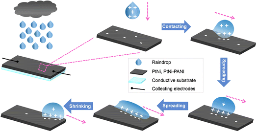 | ||
| Fig. 1 Schematic illustration of working mechanism for rain-sensitized films tailored with PtNi or PtNi-PANI material. | ||
2.4 Electrochemical characterizations
The top-view morphologies of Ni, PtNi and PtNi-PANI films were observed by a scanning electron microscope (SEM, TESCAN MIRA LMS), and the elemental mapping of the optimized PtNi-PANI was characterized. The contact angle was measured by SDC-350KS and the angle measurement method is used to Young–Laplace equation fitting. The active surface areas of PtNi and PtNi-PANI materials were determined by testing the double-layer capacitance (Cdl) at the potential window of −0.21 to −0.11 V and subsequently back to −0.21 V, employing cycle voltammetry (CV) characterizations at different scan rates of 20 mV s−1, 40 mV s−1, 60 mV s−1, 80 mV s−1 and 100 mV s−1.3. Results and discussion
The structure and working principle of PtNi or PtNi-PANI films are shown in Fig. 1. Notably, this device comprises of a conductive substrate and two collectors to record electrical signals and further output electricity.The above-mentioned film possesses abundant π-electrons as well as rainwater consists of various of ions. When dropping rainwater onto the surface of the film, cations in rain absorb π-electrons from such film to yield electrical signals. Detailedly, the cations firstly drag π-electrons at the spreading process, realizing the charging process to a maximized value at the front raindrop. And subsequently, these acting π-electrons are not dragged backward along with the pathway of target film until the rear of the raindrop, establishing a discharging process. And the π-electrons are released back to the surface of the film as well. The repeated spreading/shirking processes of raindrop form the periodical charging/discharging effect, and therefore electricity outputs. To intuitively reflect the influences of various variables on the signal values, 0.6 M NaCl aqueous solution was regarded as an ionic electrolyte instead of real rainwater unless otherwise specified.
Comparing with the SEM images of bare Ni, PtNi and PtNi-PANI materials, it can be found that Ni and PtNi have similar nanowire structures (Fig. S1a, d, S1b and e†), respectively. Pt-based alloys are recognized as a promising choice attributing to their excellent behaviors.31,32 Furthermore, PANI was successfully coated on the surface of PtNi material (Fig. S1c and f†). The common feature of PANI is that it exhibits a fully conjugated backbone with abundant delocalized π-electrons,33,34 which prompts us to consider combining PANI with PtNi alloy as an alternative to further optimize the electrical properties. Detailedly, elemental mapping (Fig. S2†) evidences the uniform distribution of Pt, Ni and N elements on the optimized PtNi-PANI film.
Additionally, the contact angle was measured to characterize the wettability differences of PtNi and PtNi-PANI films when dropping 0.6 M NaCl droplet and pure water, respectively. For PtNi (Fig. S3a and b†) or PtNi-PANI (Fig. S3c and d†), the surface of each film is of partial hydrophobicity due to the smaller contact angle of 0.6 M NaCl droplet compared to pure water. Furthermore, it can be intuitively observed that the contact angle of the optimized PtNi-PANI film (105.4°, Fig. S3c†) is greater than that of the PtNi (81.5°, Fig. S3a†), indicating a more prominent hydrophobicity of the former. This result confirms that the cations are more thoroughly desorbed at the back end of the droplets during the shrinkage process because of the more hydrophobic PtNi-PANI surface, suggesting the dependence of electricity signals on time interval. The optical videos monitor the changes of contact angles on film's surface at all stages (Movies S1 and S2† for PtNi by dropping 0.6 M NaCl and pure water, respectively. Movies S3 and S4† for PtNi-PANI by dropping 0.6 M NaCl and pure water, respectively).
This reason why the electrical signals can be generated by dropping ionic droplets on the surface of rain-sensitive films can be explained by the ohmic resistances of materials, as demonstrated in Fig. S4.† The linear I–V curves of the ohmic resistances before and after dropping the simulated rainwater are basically consistent, suggesting that the charge of either current or voltage signal is not caused by the ohmic resistance. Additionally, these films are further treated with deionized water to display no signal value and output power. This result further proves that ions in rainwater have a significant effect on electrical signal generation.
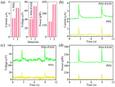
In this current work, rain-sensitive platinum (Pt)-based material applied to generate electricity in rainy environment is considered as an effective choice for harvesting rain energy. Arising from the lower electronegativity of Ni (1.92) than Pt (2.28), the free electrons in Ni atoms can tend to Pt surface to form electron-enriched PtNi alloys.29 On the other hand, because of the difference lattice constant between Pt atom and Ni atom, the latter enters into the lattice of the former, resulting in the inter-atomic extrusion and further increasing the active site of the membrane. As demonstrated in Fig. 2 and Table 1, the electrical signals arising from the rain-sensitive PtNi alloys are 3.20 ± 0.20 μA for current, 40.5 ± 5.50 μV for voltage and 195.75 ± 6.15 pW for power, respectively. However, the above data indicates that pure Pt-based materials are not suitable for practical applications due to the limited electron densities. Furthermore, the problems of expensive and scare reserves of such material seriously hinder the process of electricity production.35–37
| Films | Current (μA) | Voltage (μV) | Power (pW) |
|---|---|---|---|
| PtNi-PANI | 4.95 ± 0.35 | 69.85 ± 9.25 | 416.54 ± 14.02 |
| PtNi | 3.20 ± 0.20 | 40.5 ± 5.50 | 195.75 ± 6.15 |
Prior to this, it has been previously confirmed that the magnitude of the electrical signal is dependent upon the electron density of membrane.27 Therefore, an effective method of improving electrical signals is to enrich the electron concentration on the surface of material. PANI as a typical electron-enriched conductive polymer can bring π-electron system along whole molecular chain depending on its conjugated structure between the benzene ring and nitrogen,38–41 which can combine Pt-based alloys for further optimization of the electricity outputs. As a result, the corresponding electrical signals yielded by PtNi-PANI membrane are elevated to 4.95 ± 0.35 μA for current, 69.85 ± 9.25 μV for voltage and 416.54 ± 14.02 pW for power, respectively. Therefore, the introduction of PANI onto the surface of PtNi material instead of pure alloy is successful in improving the electrical signals. Besides, the active surface areas of PtNi and PtNi-PANI were determined by testing the electric double-layer (EDL) capacitance (Cdl) at the potential window of −0.21 to −0.11 V and subsequently back to −0.21 V, employing CV characterizations at different scan rates. As demonstrated in Fig. S5,† PtNi-PANI material exhibits a higher Cdl value (0.16 mF cm−2) compared to PtNi (0.06 mF cm−2), which means that more active sites are exposed and the specific surface area is larger in PtNi-PANI film. This result is one of the most important factors in improving electricity performance.
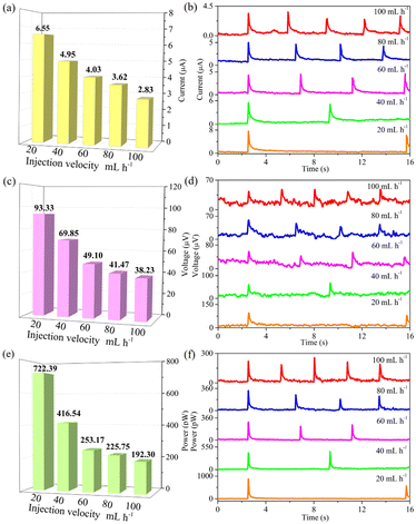
Obviously, rainfall varies from region to region. Fig. 3 represents the impact of rainfall intensity on signal values. A medical syringe filled with ionic solution is adopted for simulating the state of rainfall by controlling injection velocity. The injection velocity was controlled to tune time interval between two raindrops. By adjusting the injection velocity from 100 to 20 mL h−1, the electrical signals are collected by an Electrochemical Workstation (CHI660E). As summarized in Table 2, the corresponding electrical signals increase from 2.83 ± 0.53 μA to 6.55 ± 0.75 μA for current, from 38.23 ± 12.98 μV to 93.33 ± 7.14 μV for voltage and from 192.30 ± 54.72 pW to 722.39 ± 154.31 pW for power, respectively. The results show that rain-sensitive films tailored with PtNi-PANI material can continuously yield electricity in rainy days. Notably, as the rainfall intensity decreases, each signal value is gradually increased. One possible explanation for this phenomenon is the effect of the time interval between neighboring raindrops on electrical signals. When the time interval is enough, the cations in each raindrop can undergo a complete adsorption/desorption route with the electrons from the film, resulting in a systematic charging/discharging process. Therefore, the corresponding devices can be more suitable for light-rain environments.
| Injection velocity (mL h−1) | Current (μA) | Voltage (μV) | Power (pW) |
| 20 | 6.55 ± 0.75 | 93.33 ± 7.14 | 722.39 ± 154.31 |
| 40 | 4.95 ± 0.35 | 69.85 ± 9.25 | 416.54 ± 14.02 |
| 60 | 4.03 ± 0.63 | 49.10 ± 17.80 | 253.17 ± 34.67 |
| 80 | 3.62 ± 0.68 | 41.47 ± 12.30 | 225.75 ± 84.93 |
| 100 | 2.83 ± 0.53 | 38.23 ± 12.98 | 192.30 ± 54.72 |
In addition, the concentration of cation in rainfall is also critical for rain energy harvesting. As demonstrated in Fig. 4, the concentration of NaCl aqueous solution is considered as 0.2, 0.6 and 1.0 M. All signal values summarized in Table 3 follow an order of NaCl 0.2 M < NaCl 0.6 M < NaCl 1.0 M. These results suggest that the signal intensity elevates with increasing of ionic concentration, attributing to the enhanced EDL capacitance at rainwater/film interface. Therefore, these rain-sensitive films are more beneficial for coastal regions.
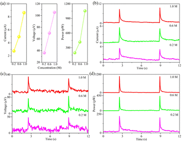 | ||
| Fig. 4 (a) A line diagram of electrical signals by dropping NaCl aqueous solution with different concentration on PtNi-PANI films. In detail, (b) current, (c) voltage and (d) power. | ||
| Concentration (M) | Current (μA) | Voltage (μV) | Power (pW) |
|---|---|---|---|
| 0.2 | 2.75 ± 0.05 | 36.10 ± 0 | 194.59 ± 7.05 |
| 0.6 | 4.95 ± 0.35 | 69.85 ± 9.25 | 416.54 ± 14.02 |
| 1.0 | 8.65 ± 0.45 | 105.45 ± 7.55 | 1054.47 ± 5.62 |
Based on the above-mentioned working mechanism of converting rain energy into electricity, the composition of rainwater also has an important influence on electrical signals. In this fashion, 0.6 M chloride aqueous solutions consisting of HCl, LiCl, NaCl, KCl, NH4Cl and MgCl2 are applied to experimental research. As recorded in Fig. 5 and Table 4, all electrical signals arising from PtNi-PANI film satisfy an order of HCl > LiCl > NaCl > KCl > NH4Cl, which is attributed to the fact that the ionic radius meets [r(H+) = 32 pm] < [r(Li+) = 60 pm] < [r(Na+) = 95 pm] < [r(K+) = 122 pm] < [r(NH4+) = 133 pm]. According to Coulomb's effect, as the radius is gradually reduced, the corresponding electrostatic adsorption between electrons and cations is improved, resulting in the higher EDL capacitance. According to the report,42 it has been found that the Hofmeister effect and electrostatic interaction can synergistically enhance the ionic conductivity of organohydrogels. However, the electrostatic interaction between the lithium and sodium bonds plays a more crucial role than the Hofmeister effect in improving conductivity. This conclusion may be applicable to our work, analogically, where the electrostatic interaction between cations (Li+, Na+, K+, etc.) and electrons exceeds the Hofmeister effect. Moreover, the electrostatic interaction satisfies an order of Li+ > Na+ > K+, suggesting that the electrical signal meets LiCl > NaCl > KCl.
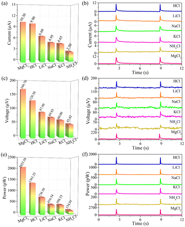 | ||
| Fig. 5 (a and b) Current, (c and d) voltage and (e and f) power produced by dropping 0.6 M chlorides aqueous solution on PtNi-PANI films. | ||
| Signals | HCl | LiCl | NaCl | KCl | NH4Cl | MgCl2 |
|---|---|---|---|---|---|---|
| Current (μA) | 9.90 ± 0 | 6.60 ± 0.10 | 4.95 ± 0.35 | 4.65 ± 0.25 | 2.50 ± 0.20 | 10.30 ± 0.10 |
| Voltage (μV) | 128.50 ± 3.50 | 87.90 ± 6.40 | 69.85 ± 9.20 | 60.00 ± 4.00 | 45.42 ± 4.71 | 166.70 ± 0.10 |
| Power (pW) | 1361.25 ± 34.65 | 736.58 ± 8.23 | 416.54 ± 14.02 | 398.55 ± 47.90 | 154.91 ± 6.24 | 2033.58 ± 9.94 |
Furthermore, in comparison to NaCl solution, such rain-sensitive PtNi-PANI film can convert more rain energy into electricity from MgCl2 solution. One reasonable explanation is that not only the latter has a smaller ionic radius, but the charge number elevates. The Hofmeister series of Mg2+ is similar to that of Li+, while the former can bring two charges compared to one charge of Li+. Thus, Mg2+ with two transferable electrons exhibits the greater volume density than Li+.
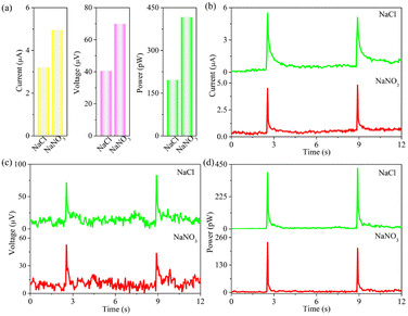
In addition, anions from rainwater such as Cl− and NO3− are also significant parameters in influencing the power outputs. And the corresponding results are recorded in Fig. 6 and Table 5. We can conclusion that the signal values follow an order of NaCl > NaNO3. This is because the ionic radius of NO3− is smaller than that of Cl−, leading to the adsorption capacity of NO3− > Cl− but the opposite electrostatic adsorption capacity between Na+ and electron. Besides, the Hofmeister series of Cl− is higher than that of NO3−, indicating the better conductivity of the former.42 The corresponding electrical signal of NaCl is higher than that of NaNO3. Therefore, NaCl aqueous solution is more suitable for forming electricity-generating capacity. Notably, the free electrons in Ni atoms can tend to Pt surface to form electron-enriched PtNi alloys arising from the lower electronegativity of Ni (1.92) compared to Pt (2.28). This phenomenon induces the aggregation of electrons around Pt, which can effectively retard the reaction between Pt and Cl−.43–45
| Chlorides | Current (μA) | Voltage (μV) | Power (pW) |
|---|---|---|---|
| NaCl | 4.95 ± 0.35 | 69.85 ± 9.25 | 416.54 ± 14.02 |
| NaNO3 | 4.20 ± 0 | 42.85 ± 2.15 | 220.56 ± 13.44 |
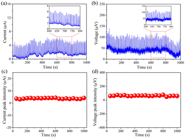
Long-term stability is defined as a fundamental requirement to assess the real performances of rain-sensitive films in practical applications. To address this problem, 0.6 M NaCl aqueous solution was persistently dropped onto such device for more than 1000 s, as demonstrated in Fig. 7, the baselines of these images including current and voltage have slight fluctuation, but the overall signal values stay relatively stable. As a result, such rain-sensitive device has excellent durability in practical application of harvesting rain energy.
So far, all electrical and electrochemical measurements are performed by dropping simulated rainwater onto rain-sensitive device. To further reflect the real application of such device in an actual rainy environment, the real rain arising from Qingdao has been used to study the signal performances. And the corresponding ionic components are summarized in Table S1.† Obviously, The real rainwater is not pure water, which contains various of cations (Na+, NH4+, Mg2+, etc.) and anions (Cl−, NO3−, SO42−, etc.). Moreover, the composition of rainwater is closely related to the region, environment, climate, etc. Regardless of the ionic component of rainwater, power generation can be achieved by stimulated the rain-sensitive films. In this fashion, as recorded in Fig. 8 and Table S2,† the electric signals are 0.27 ± 0.06 μA per drop of current, 36.20 ± 11.70 μV per drop of voltage and 20.87 ± 3.70 pW per drop of power, respectively. We can conclude that although the signal values are faint due to the low ion concentration, one promising strategy to address this issue is to improve the system by increasing the area available for continuously electricity output.
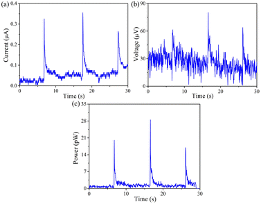 | ||
| Fig. 8 (a) Current, (b) voltage and (c) power yielded by dropping real rainwater onto PtNi-PANI films. | ||
4. Conclusions
In summary, rain-sensitive films tailored with PtNi and further PtNi-PANI materials have been successfully applied to yield electricity in rainy atmosphere. According to the charging/discharging EDL capacitances, the electric signals including current and voltage are obtained in tens to thousands of micron levels. These results indicate that the signal values are highly dependent onto the concentration, radius and charges of rainwater, as well as the concentration of electrons. Moreover, so-called rain-sensitive films have remarkable long-term durability and potential practical applicability. Although the current work is far from being optimized, the electron electrons and membrane properties can be further improved for power generation in practical application.Author contributions
Yingli Wang: conceived ideas, experimental research, data curation, test analysis, conclusion validation. Jialong Duan: supervision. Qiyao Guo: funding support. Yuanyuan Zhao: polished the article language. Xiya Yang: provided testing help. Qunwei Tang: subject supervision, project administration, funding acquisition.Conflicts of interest
The authors declare that they have no known competing financial interests or personal relationships that could have appeared to influence the work reported in this paper.Acknowledgements
This work was supported by National Key Research and Development Program of China (2021YFE0111000), the National Natural Science Foundation of China (61774139, 62004083, U1802257, 22109019, 22179051), the Fundamental Research Funds for the Central Universities (21622410) and National Natural Science Foundation of China (62204098).References
- L. Qin, S. Raheem, M. Murshed, X. Miao, Z. Khan and D. Kirikkaleli, Sustainable Dev., 2021, 29, 1138–1154 CrossRef.
- S. K. Rathor and D. Saxena, Int. J. Energy Res., 2020, 44, 4067–4109 CrossRef.
- Z. Chen, R. Kleijn and H. Lin, Environ. Sci. Technol., 2023, 57, 1080–1091 CrossRef CAS PubMed.
- J. Schmidt, K. Gruber, M. Klingler, C. Klockl, L. R. Camargo, P. Regner, O. Turkovska, S. Wehrle and E. Wetterlund, Energy Environ. Sci., 2019, 12, 2022–2029 RSC.
- M. S. Zantye, A. Arora and M. M. F. Hasan, Energy Environ. Sci., 2021, 14, 3986–4008 RSC.
- P. Wang, X. Chen, G. Sun, C. Wang, J. Luo, L. Yang, J. Lv, Y. Yao, W. Luo and Z. Zou, Angew. Chem., Int. Ed., 2021, 60, 1390–1395 CrossRef CAS PubMed.
- L. Niu, X. Li, Y. Zhang, H. Yang, J. Feng and Z. Liu, ACS Sustainable Chem. Eng., 2022, 10, 13081–13090 CrossRef CAS.
- M. Ashraf, M. Ayaz, M. Khan, S. F. Adil, W. Farooq, N. Ullah and M. N. Tahir, Energy Fuels, 2023, 37, 6283–6301 CrossRef CAS.
- E. Kabir, P. Kumar, S. Kumar, A. A. Adelodun and K.-H. Kim, Renewable Sustainable Energy Rev., 2018, 82, 894–900 CrossRef.
- A. Datta and R. Krishnamoorti, Environ. Sci. Technol., 2023, 57, 2084–2092 CrossRef CAS PubMed.
- B. Zhang, C. Zhang, O. Yang, W. Yuan, Y. Liu, L. He, Y. Hu, Z. Zhao, L. Zhou, J. Wang and Z. Wang, ACS Nano, 2022, 16, 15286–15296 CrossRef CAS PubMed.
- X. Yu, H. Zheng, T. Lu, R. Shen, Y. Yan, Z. Hao, Y. Yang and S. Lin, RSC Adv., 2021, 11, 19106–19112 RSC.
- X. Fu, T. Bu, C. Li, G. Liu and C. Zhang, Nanoscale, 2020, 12, 23929–23944 RSC.
- M. Rahman, F. Rubaiya, N. Islam, K. Lozano and A. Ashraf, ACS Appl. Mater. Interfaces, 2022, 14, 38162–38171 CrossRef CAS PubMed.
- S. Chatterjee, S. R. Burman, I. Khan, S. Saha, D. Choi, S. Lee and Z.-H. Lin, Nanoscale, 2020, 12, 17663–17697 RSC.
- K. Wang, Y. Zhang, X. Luo, L. Zhu and Z. Wang, ACS Appl. Electron. Mater., 2022, 4, 4764–4771 CrossRef CAS.
- H. Chen, C. Xing, Y. Li, J. Wang and Y. Xu, Sustainable Energy Fuels, 2020, 4, 1063–1077 RSC.
- F. Yu, G. Liu, Z. Chen, L. Zhang, X. Liu, Q. Zhang, L. Wu and X. Wang, ACS Appl. Mater. Interfaces, 2022, 14, 40082–40092 CrossRef CAS PubMed.
- X.-L. Li, K.-C. Long, G. Zhang, W.-T. Zou, S.-Q. Jiang, D.-Y. Zhang, J.-Q. Zhou, M.-J. Liu and G.-J. Yang, ACS Appl. Energy Mater., 2021, 4, 7952–7958 CrossRef CAS.
- Q. Dang, W. Chen, Y. Li and L. Tang, ACS Sustainable Chem. Eng., 2022, 10, 935–945 CrossRef CAS.
- H. Zhang, L. Huang, J. Zhai and S. Dong, J. Am. Chem. Soc., 2019, 141, 16416–16421 CrossRef CAS PubMed.
- D. Liu, X. Yang, J. Gao, Q. Ran, G. Zhou, J. Yuan, D. Zheng, J. Guo, L. Zhao and Q. Tang, Energy Technol., 2023, 11, 2201044 CrossRef CAS.
- M. A. Fulazzaky, A. Syafiuddin, M. Roestamy, Z. Yusop, J. Jinbi and D. D. Prasetyo, ACS ES&T W, 2022, 2, 604–615 CAS.
- A. Strauss, B. Reyneke, M. Waso and W. Khan, Environ. Sci.: Water Res. Technol., 2018, 4, 976–991 RSC.
- Q. Tang, X. Wang, P. Yang and B. He, Angew. Chem., Int. Ed., 2016, 55, 5243–5246 CrossRef CAS PubMed.
- J. Yin, X. Li, J. Yu, Z. Zhang, J. Zhou and W. Guo, Nat. Nanotechnol., 2014, 9, 378–383 CrossRef CAS.
- Y. Wang, J. Duan, Y. Zhao and Q. Tang, Nano Energy, 2017, 41, 293–300 CrossRef CAS.
- Q. Tang, H. Zhang, B. He and P. Yang, Nano Energy, 2016, 30, 818–824 CrossRef CAS.
- Q. Tang, Y. Duan, B. He and H. Chen, Angew. Chem., Int. Ed., 2016, 55, 14412–14416 CrossRef CAS PubMed.
- Y. Wang, J. Duan, Y. Zhao, Z. Jiao, B. He and Q. Tang, Electrochim. Acta, 2018, 285, 139–148 CrossRef CAS.
- Q. Lu, X. Zhao, R. Luque and K. Eid, Coord. Chem. Rev., 2023, 493, 215280 CrossRef CAS.
- K. Mariyappan, T. Mahalakshmi, T. Roshni, P. Ragupathy and M. Ulaganathan, Adv. Mater. Interfaces, 2023, 10, 2202007 CrossRef CAS.
- Y.-H. Chang, C.-C. Chang, L.-Y. Chang, P.-C. Wang, P. Kanopaka and M.-H. Yeh, Nano Energy, 2023, 112, 108505 CrossRef CAS.
- S. Palsaniya, T. Pal and S. Mukherji, Chem. Eng. J., 2023, 466, 143025 CrossRef CAS.
- J. Theerthagiri, A. R. Senthil, J. Madhavan and T. A. Maiyalagan, ChemElectroChem, 2015, 2, 928–945 CrossRef CAS.
- M. Batmunkh, M. J. Biggs and J. G. Shapter, Small, 2015, 11, 2963–2989 CrossRef CAS PubMed.
- S. Yun, A. Hagfeldt and T. Ma, Adv. Mater., 2014, 26, 6210–6237 CrossRef CAS PubMed.
- K. H. Lee, B. J. Park, D. Song, I. J. Chin and H. J. Choi, Polymer, 2009, 50, 4372–4377 CrossRef CAS.
- Q. Hao, W. Lei, X. Xia, Z. Yan, X. Yang, L. Lu and X. Wang, Electrochim. Acta, 2010, 55, 632–640 CrossRef CAS.
- C. Laslaum, Z. Zujovic and J. Travas-Sejdic, Prog. Polym. Sci., 2010, 35, 1403–1419 CrossRef.
- Q. Hao, X. Wang, L. Lu, X. Yang and V. M. Mirsky, Macromol. Rapid Commun., 2005, 26, 1099–1103 CrossRef CAS.
- Y. Wu, Y. Mu, Y. Luo, C. Menon, Z. Zhou, P. Chu and S.-P. Feng, Adv. Funct. Mater., 2022, 32, 2110859 CrossRef.
- X.-Q. Zhang, Y.-X. Xiao, G. Tian, X. Yang, Y. Dong, F. Zhang and X.-Y. Yang, Chem.–Eur. J., 2023, 29, e202202811 CrossRef CAS PubMed.
- K. Xiang, Z. Song, D. Wu, X. Deng, X. Wang, W. You, Z. Peng, L. Wang, J.-L. Luo and X.-Z. Fu, J. Mater. Chem. A, 2021, 9, 6316–6324 RSC.
- S. Ye, W. Xiong, P. Liao, L. Zheng, X. Ren, C. He, Q. Zhang and J. Liu, J. Mater. Chem. A, 2020, 8, 11246–11254 RSC.
Footnote |
| † Electronic supplementary information (ESI) available: Appendix A. See DOI: https://doi.org/10.1039/d3ra03526c |
| This journal is © The Royal Society of Chemistry 2023 |

