
 Open Access Article
 This Open Access Article is licensed under a Creative Commons Attribution-Non Commercial 3.0 Unported Licence
Taurine as a powerful passivator of perovskite layer for efficient and stable perovskite solar cells†
Xian Hou‡
 *ab,
Zhenjia Yuan‡a,
Jinlong Liua,
Hongzhen Maa and
Fucheng Yu*ab
*ab,
Zhenjia Yuan‡a,
Jinlong Liua,
Hongzhen Maa and
Fucheng Yu*ab
aInstitute of Optoelectronic Materials and Devices, School of Materials Science and Engineering, Lanzhou University of Technology, Lanzhou, 730050, Gansu, China. E-mail: houx@lut.edu.cn; yufc72@163.com
bState Key Laboratory of Advanced Processing and Recycling of Non-ferrous Metals, Lanzhou University of Technology, Lanzhou 730050, Gansu, China
First published on 5th June 2023
Abstract
Due to the ionic lattice property and the solution manufacture process of the perovskite light absorbing layer, there are several intrinsic defects (such as vacancies and low coordination Pb2+ and I−) in perovskite films, which cause undesired photon-generated carrier recombination in the perovskite solar cells (PSCs) and seriously affect the power conversion efficiency (PCE) of devices. Defect passivation strategy is one of the most effective ways to eliminate the defects in perovskite films. Herein, a multifunctional Taurine molecule was introduced into CH3NH3PbI3 (MAPbI3) perovskite precursor solution to passivate the defects. It was found that Taurine with sulfonic acid (–SOOOH) and amino (–NH2) groups can bind with uncoordinated Pb2+ and I− ions, respectively, which can significantly reduce the defect density and suppress the carrier non-radiative recombination. Under atmospheric environment, non-hole transport layer FTO/TiO2/perovskite/carbon structure PSCs were prepared. The device with Taurine showed a PCE of 13.19%, which is 17.14% higher than that of the control device (11.26%). With the suppressed defects, the Taurine passivated devices also showed enhanced device stability. The unencapsulated Taurine passivated device stored in ambient air after 720 h (temp. ∼25 °C and RH ∼25%) maintained 58.74% original PCE, while that of the control device was only about 33.98%.
1 Introduction
Owing to their high power conversion efficiency (PCE), solution processability, and low cost of materials, organic–inorganic hybrid perovskite solar cells (PSCs) have attracted widespread attention in photovoltaics. At present, PSCs have achieved a PCE of 25.8%,1 although it is anticipated to be close to 33.7% for the Shockley–Quessel limit of unijunction solar cells.2 These great achievements can be attributed to the excellent light absorbing property, relatively low excitation energy, long carrier lifetime, and active carrier mobility of halide perovskite materials.3–7However, the ionic lattice characteristics and relatively low formation energy of halide perovskite materials give rise to various intrinsic defects, such as vacancies and low coordination Pb2+ and I− ions, during film formation and device operation.8–10 These defects in the perovskite lattice can act as carrier nonradiative recombination sites and seriously lower the open-circuit voltage (VOC) and fill factor (FF) of the devices. In addition, the defects at grain boundaries and surfaces assist ion migration, and component loss accelerates perovskite decomposition, especially in thermal and humid environments.11–15 Therefore, eliminating or passivating the defects in the perovskite light absorbing layer is very important to further enhance the PCE and stability of PSCs.
Several attempts have been applied to eliminate or passivate the defects.16 Especially, additive engineering has been proven to be an effective strategy to influence the defects, where the passivation agents commonly used include inorganic metal salts,17,18 polymeric polymers,19 and organic small molecules.20 Among them, some passivators with electron-rich functional groups, such as pyridine21 and thiophene,22 can bind to the uncoordinated Pb2+ ions in the perovskite films, thus effectively reducing the deep level defects. On the other hand, fullerene halide complexes and other electron-deficient Lewis acid molecules can interact with the dissociative I− ions, causing shallow level defects.23
Furthermore, some small molecules have both positive and negative functional groups and can passivate both the positively charged defects and negatively charged defects by forming ionic bonds with under-coordinated Pb2+ and I− ions.23–26 Sodium dodecyl benzene sulfonate (SDBS) has been used in perovskite crystals to modify the crystallization behavior and passivate defects. The –SOOOH group of SDBS has been found to interact with uncoordinated Pb2+, while the –NH2 group can also form electrostatic interactions with uncoordinated I− ions in perovskites. By working together, the –SOOOH and –NH2 groups of SDBS achieved a remarkable reduction in the film defect density, enabling the development of high-performance PSCs based on SDBS-passivated perovskite films. These PSCs demonstrated an outstanding PCE of 20.88% and remarkable stability.24 Yang et al.23 introduced ammonium benzenesulfonate (ABS) into CH3NH3PbI3 (MAPbI3) perovskite films, which contains both –NH2 and –SOOOH groups. The –SOOO− group acted as an electron donor, effectively neutralizing the positively charged uncoordinated Pb ions. Meanwhile, the –NH3+ group simultaneously passivates the negative MA vacancies and Pb–I anti-sites, contributing to the enhanced performance of the PSCs. This shows that passivator molecules containing both positively and negatively charged functional groups are more effective than passivators with single functional groups to passivate charged defects in perovskite films.
Herein, Taurine with –SOOOH and –NH2 functional groups was introduced into MAPbI3 films. The –SOOOH and –NH2 groups in Taurine can effectively bind with the uncoordinated Pb2+ and I− ions in MAPbI3, respectively. In the atmospheric condition, the Taurine passivated perovskite films were used as the light absorbing layer for PSCs with FTO/TiO2/perovskite/carbon structure. The device exhibited a PCE of 13.19% under 1 Sun illumination (AM 1.5 G), which is 17.14% higher than that of the un-passivated device. Moreover, with the bifunctional passivation, the stability of the device was significantly enhanced. The unencapsulated device with Taurine maintained 58.74% of the original PCE in the atmospheric condition (temp. ∼25 °C and RH ∼25%) after 720 hours, while the control device could only maintain about 33.98% of its initial PCE.
2 Experimental section
2.1 Reagents and materials
The F-doped tin oxide-coated (FTO, sheet resistance <14 Ω/□) glass substrate, methylammonium iodide (MAI, 99.5%), and lead iodide (PbI2, 99.99%) were purchased from Advanced Election Technology Co, Ltd. Titanium(IV) isopropoxide (TPT, 99.9%), dimethyl sulfoxide (DMSO, 99.8%), dimethylformamide (DMF, 99.5%), chlorobenzene (CB, 99.5%), absolute ethanol (99.5%), and Taurine (99%) were obtained from Aladdin. Titanium dioxide spin coating paste (18NR-T) was purchased from Dyesol. Low temperature carbon electrode paste (99%, sheet resistance <20 Ω/□) was purchased from Shanghai MaterWin New Materials Co., Ltd, China.2.2 Device fabrication
![[thin space (1/6-em)]](https://www.rsc.org/images/entities/char_2009.gif) :25) was spin-coated onto the compact TiO2 layer at 4000 rpm for 30 s and heated at 500 °C for 30 min to form a mesoporous TiO2 layer (n-TiO2).:4 v/v) and stirred for over 12 h before use. To obtain Taurine passivated MAPbI3 precursors, 0.1 mg mL−1 1-Taurine, 0.2 mg mL−1 2-Taurine, 0.4 mg mL−1 4-Taurine, and 0.6 mg mL−1 6-Taurine were added into the MAPbI3 precursor solution. The perovskite precursor solution was spin-coated on FTO/c-TiO2/n-TiO2 substrates at 1000 rpm for 10 s and then 3500 rpm for 30 s, at the beginning of 4th s of the second spin-coating step, 500 μL CB was dripped onto the rotating film. Subsequently, the films were transferred to a 100 °C hot plate and annealed for 10 min.
:25) was spin-coated onto the compact TiO2 layer at 4000 rpm for 30 s and heated at 500 °C for 30 min to form a mesoporous TiO2 layer (n-TiO2).:4 v/v) and stirred for over 12 h before use. To obtain Taurine passivated MAPbI3 precursors, 0.1 mg mL−1 1-Taurine, 0.2 mg mL−1 2-Taurine, 0.4 mg mL−1 4-Taurine, and 0.6 mg mL−1 6-Taurine were added into the MAPbI3 precursor solution. The perovskite precursor solution was spin-coated on FTO/c-TiO2/n-TiO2 substrates at 1000 rpm for 10 s and then 3500 rpm for 30 s, at the beginning of 4th s of the second spin-coating step, 500 μL CB was dripped onto the rotating film. Subsequently, the films were transferred to a 100 °C hot plate and annealed for 10 min.2.3 Measurements and characterization
Fourier transform infrared (FT-IR) spectroscopy was carried out using a Thermo Fisher Scientific FTIR-670 spectrometer to characterize the mechanism of action of the passivators. X-ray diffraction (XRD) (Bruker D8-ADVANCE diffractometer), field emission scanning electron microscopy (FESEM) (Germany ZEISS Sigma 300), and scanning probe microscopy (SPM) (BRUKER MultiMode 8-HR) techniques were used for characterizing the grains of the perovskite films. Absorption properties of the photons of the perovskite films were compared by UV-vis absorption spectra (PerkinElmer UV-vis Lambda3 spectrometer).The current density–voltage (J–V) measurements of the devices were performed using an Enlitech SS-X equipment under AM 1.5 G 100 mW cm−2. The external quantum efficiency (EQE) spectra were measured using the PV/solar cell quantum efficiency measurement system (QE-R, Enlitech). The electrochemical impedance spectroscopy (EIS) and dark J–V curves were obtained using an electrochemical workstation (CHI660D).
3 Results and discussion
The electrostatic potential (ESP) map was calculated to investigate the surface electron distribution of Taurine, as shown in Fig. 1a. The color shift from blue to red indicates that the charge density increased from 6.348 × 10⁻² to −1.317 × 10⁻¹. Apparently, the –NH2 and –SOOOH groups were located in the electron-deficient and electron-rich region, respectively. The electron-rich –SOOOH group was more eager to bind with uncoordinated Pb2+ ions to reduce the deep-level defects in the perovskite films.23–28 On the other hand, the electron-deficient –NH2 group was observed to bind with free I− ions to passivate the shallow-level defects.23–29 The schematic diagram of the Taurine passivation process is shown in Fig. 1b.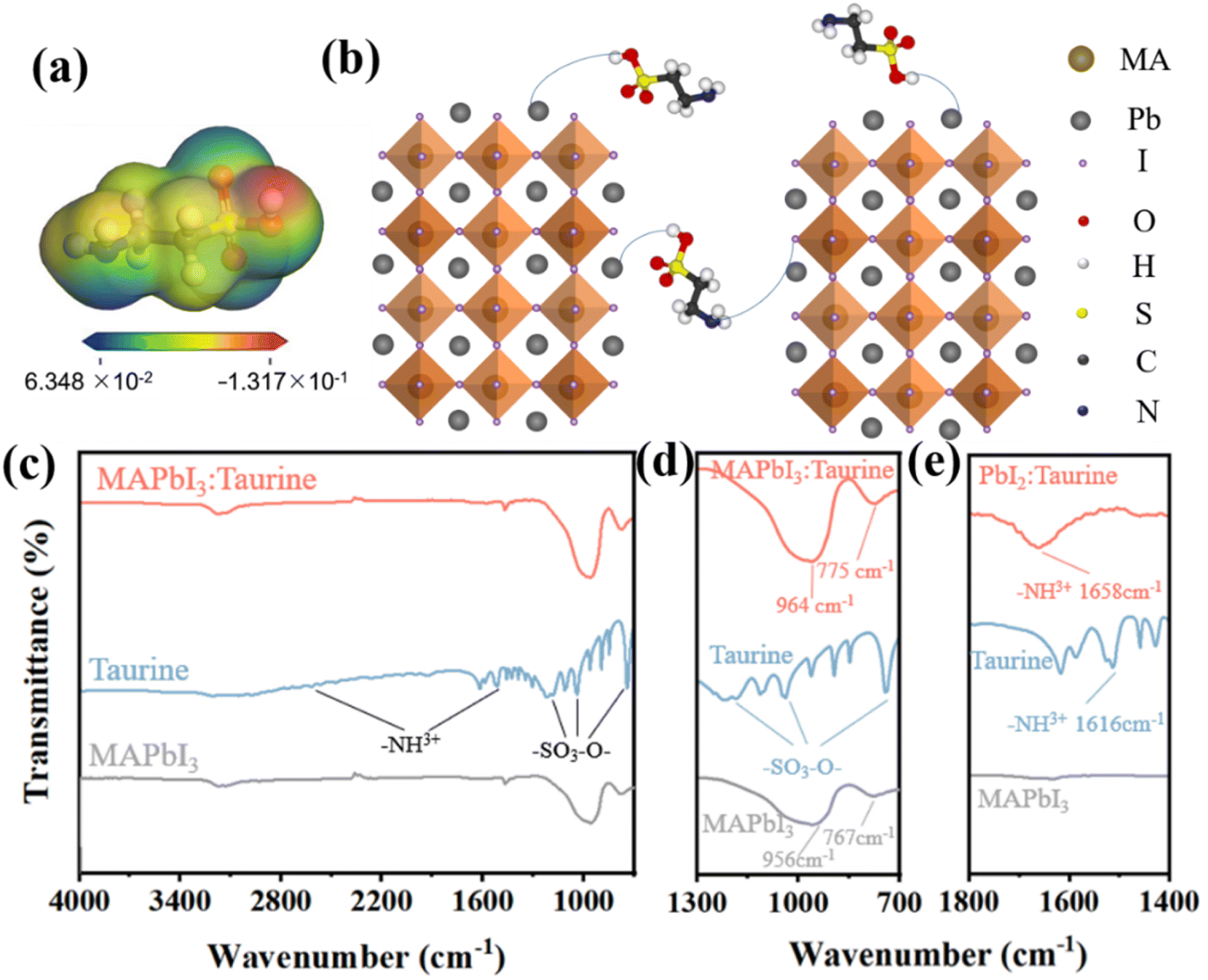 | ||
| Fig. 1 (a) Electrostatic potential (ESP) map of Taurine. (b) The schematic diagram of Taurine passivation. (c) FT-IR spectroscopy of MAPbI3, Taurine, and MAPbI3:Taurine. (d) The partially enlarged detail FT-IR spectrum of (c). (e) The FT-IR spectroscopy of PbI2, Taurine, and PbI2:Taurine. | ||
To verify the passivation effect mentioned above, FT-IR spectroscopy was carried out. Fig. 1c shows the FT-IR spectrum of MAPbI3, Taurine, and MAPbI3:Taurine. Fig. 1d displays a partially enlarged detailed FT-IR spectrum of Fig. 1c. In the Taurine curve, the –SOOO− group exhibits its characteristic peaks at 744, 1035, and 1182 cm−1, while the characteristic peaks of –NH3+ are located at 1151 and 2618 cm−1. For MAPbI3, the wide bands at 956 and 767 cm−1 are attributed to Pb2+. However, these two peaks significantly moved to 964 and 775 cm−1 when Taurine was added to MAPbI3, indicating that Pb2+ and –SOOO– have formed a chemical bond.30 To clarify the bonding interaction between the –NH3+ group in Taurine and I− ions in MAPbI3, and confirm that the bonding with I− actually came from the –NH3+ in Taurine rather than MAPbI3, FT-IR spectroscopy was carried out for PbI2, Taurine, and PbI2:Taurine, as shown in Fig. 1e. When Taurine was introduced in the PbI2 film, the –NH3+ characteristic peak at 1616 cm−1 shifted to 1658 cm−1. The increase in the –NH3+ stretching wavenumber in the PbI2:Taurine film could be due to the reduced spatial symmetry, which corresponds to the binding of I− and –NH3+, and thus the symmetric stretching vibration became harder. Therefore, –SOOOH and –NH2 groups of Taurine can bind with uncoordinated Pb2+ and I−, respectively. This combination renders under-coordinated Pb and I ions more stable, making it harder to lose or gain electrons.31–35
The presence of Taurine can also affect the perovskite crystal growth. Fig. 2a–e shows the top view SEM images of perovskite films with different concentrations of Taurine. The average grain sizes are 175.9, 196.2, 235.6, 297.5, and 159.7 nm for the perovskite films of (a) control, (b) 1-Taurine, (c) 2-Taurine, (d) 4-Taurine, and (e) 6-Taurine, respectively, and the corresponding grain size distribution are shown in Fig. S1.† The interaction of Taurine with Pb2+ and I− ions of MAPbI3 could be retarding the crystallization process, which is beneficial to building high-quality perovskite films, and the size of the perovskite grains gradually increased with the increase in Taurine concentration. However, the 6-Taurine sample showed an inferior film quality due to the agglomeration of excess Taurine as blocks or flakes in the wet MAPbI3 film, which hindered the grain continuity and resulted in small grains. We also looked at the changes in film roughness after adding taurine molecules Fig. S2† shows the SPM images of control MAPbI3 perovskite film and 4-Taurine perovskite film. The root mean square (RMS) of roughness was clearly reduced from 20.2 nm to 10.5 nm after taurine passivation. The more flat and uniform perovskite film was beneficial to carrier transportation.
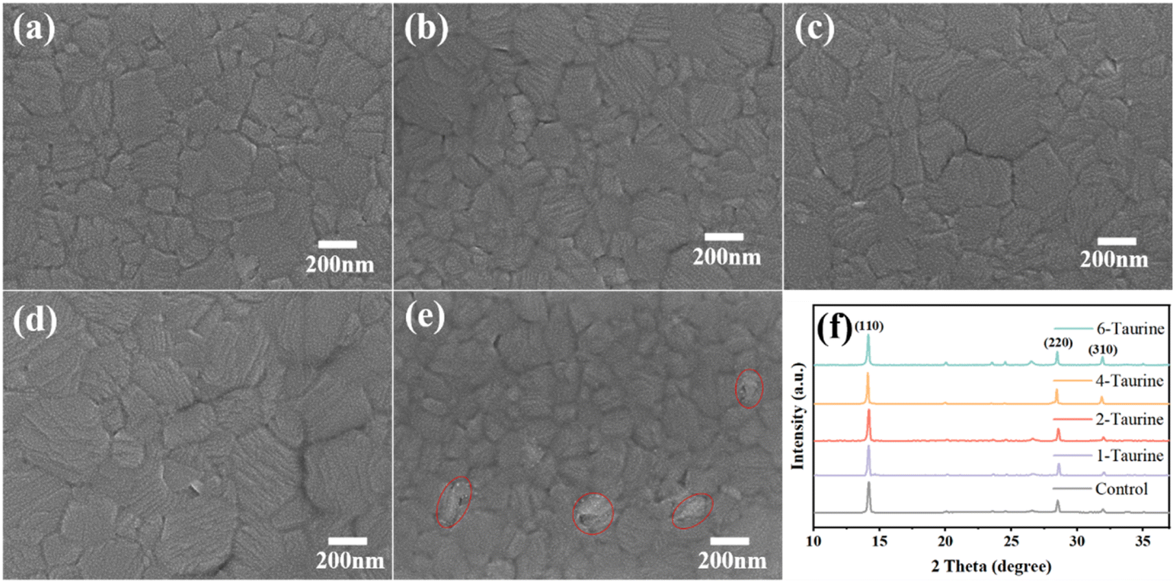 | ||
| Fig. 2 The top view SEM images of MAPbI3 films (a) control, (b) 1-Taurine, (c) 2-Taurine, (d) 4-Taurine, and (e) 6-Taurine. (f) The XRD spectrum of perovskite films with Taurine. | ||
The Taurine additive effect on the MAPbI3 film crystallization was also analysed using XRD. As shown in Fig. 2f, all films showed similar XRD spectra, and the diffraction peaks at 14.15°, 20.05°, 28.47°, and 31.94° can be attributed to the (110), (112), (220), and (310) planes of the perovskites, respectively, indicating the presence of a tetragonal crystal structure of MAPbI3. There is no clear peak shift or new peak appearing after Taurine passivation, suggesting that Taurine did not alter the formation of the MAPbI3 lattice. Table S1† shows the full width at half maximum (FWHM) of (110) peak changes, and the 4-Taurine film presents the smallest FWHM, which was consistent with the SEM images of the perovskite films.
To further investigate the impact of Taurine on the PSC performances, FTO/n-TiO2/c-TiO2/perovskite/C structure (Fig. S3†) PSCs were assembled in air. Fig. S4† shows the reverse scanning J–V curves of the control and different concentrations of Taurine passivated devices. The control PSCs exhibited a maximum PCE of 11.26% with a VOC of 0.96 V, a JSC of 21.80 mA cm−2, and an FF of 53.80%, while the 1-Taurine device showed an enhanced PCE of 11.92%. The PCE value of the devices gradually increased with the enriched Taurine; the 4-Taurine device showed remarkable photovoltaic (PV) performance with a PCE of 13.19% with a VOC of 1.02 V, a JSC of 22.30 mA cm−2, and an FF of 57.99%. However, due to the inferior quality of perovskite films, the 6-Taurine device demonstrated a reduced PCE of 10.37%. The specific PV parameters are summarized in Table 1. To analyse the enhanced PCE performance, UV-vis absorption spectra were measured to investigate the changes in the light absorption properties of the films by Taurine passivation. As shown in Fig. 3a, with the gradual increase in the concentration of Taurine the absorption intensity of the perovskite films improved significantly, and the 4-Taurine film showed the highest light absorption intensity, which was mainly caused by the largest grain sizes.
| Samples | PCE (%) | VOC (V) | JSC (mA cm−2) | FF (%) |
|---|---|---|---|---|
| Control | 11.26 | 0.96 | 21.80 | 53.80 |
| 1-Taurine | 11.92 | 0.97 | 21.40 | 57.42 |
| 2-Taurine | 12.01 | 1.02 | 21.90 | 53.76 |
| 4-Taurine | 13.19 | 1.02 | 22.30 | 57.99 |
| 6-Taurine | 10.37 | 0.96 | 20.50 | 52.69 |
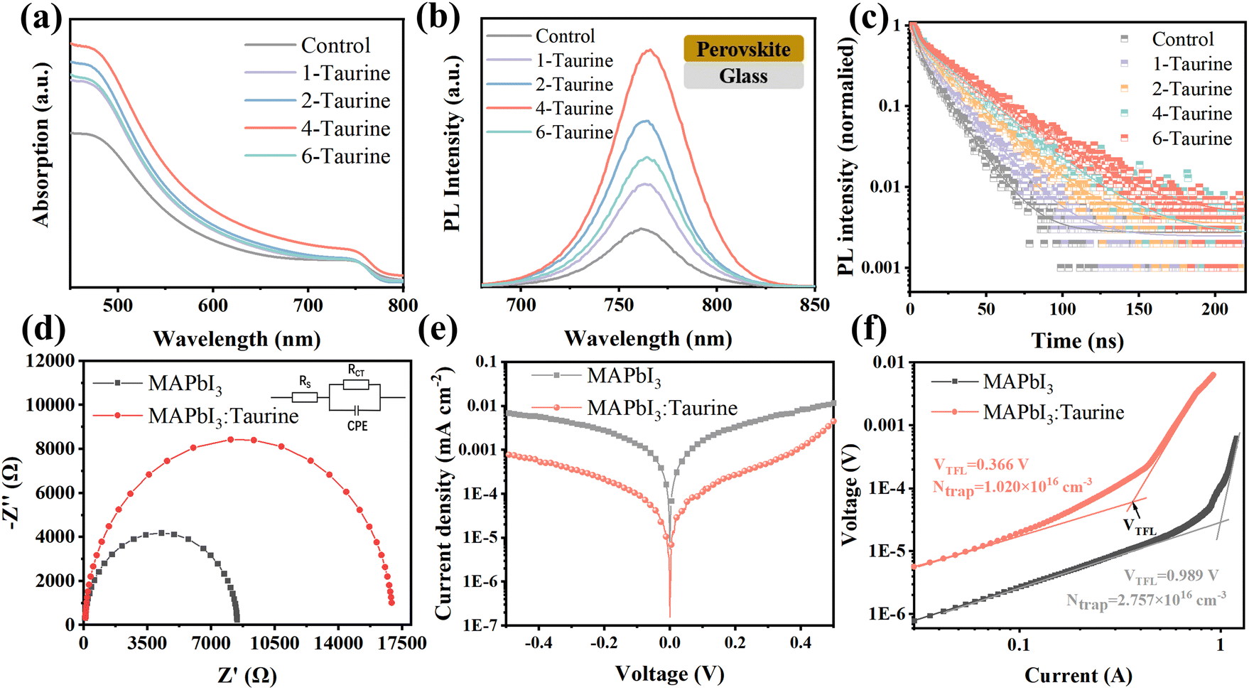 | ||
| Fig. 3 The (a) UV-vis spectra, (b) PL steady-state fluorescence spectra, (c) TRPL spectra of perovskite films. The (d) EIS, (e) dark J–V log curves of MAPbI3, and MAPbI3:Taurine devices. (f) The dark current–voltage curves of HTL-only devices. | ||
Steady-state photoluminescence (PL) spectroscopy and time-resolved photoluminescence (TRPL) spectroscopy were used to investigate the photo-carrier behaviour. Fig. 3b shows the PL spectra of perovskite films, which were deposited on glass. All of the films displayed the same PL peak at 762 nm; the PL intensity of the films gradually increased with the increase in the concentration of Taurine, and the 4-Taurine film exhibited the strongest PL intensity. The results indicated a significant increase in the carrier concentration due to the superior film quality of 4-Taurine. Moreover, the decreased defects increased the carrier lifetime, as verified by the TRPL spectra shown in Fig. 3c. To determine the carrier lifetime, a biexponential decay function was used to fit the TRPL curves. This fitting process yielded two essential types of carrier decay lifetime parameters and two characteristic PL decay amplitude parameters, τ1 and τ2 and A1 and A2, respectively.36 Specifically, the slower decay rate component is linked to bimolecular radiative recombination and is represented by τ1, while the faster decay lifetime component results from defect-induced nonradiative recombination and is represented by τ2. The average carrier lifetime (τavg) can be calculated by the equation of τavg = (A1 × τ12 + A2 × τ22)/(A1 × τ1 + A2 × τ2). The control film has a τavg of 12.42 ns, and the τavg value of the films steadily increased with increase in the concentration of Taurine. The 4-Taurine film showed the longest τavg of 25.26 ns, which is beneficial to the carrier transportation. The detailed average carrier lifetimes are listed in Table S2.†
As the 4-Taurine device demonstrated the best PV performance, the following discussion is focused on the 4-Taurine device, which is named as MAPbI3:Taurine. Fig. 3d shows the Nyquist plots of devices under dark conditions with 0.7 V bias, which reveals the interfacial charge transfer and recombination dynamics. A smaller series resistance (RS) of 9.37 Ω was displayed by the MAPbI3:Taurine device than the MAPbI3 device (46.20 Ω), which indicates faster carrier transportation in the MAPbI3:Taurine device.37,38 On the other hand, the charge recombination resistance (Rrec) was significantly raised from 8.38 kΩ to 16.87 kΩ by the accession of Taurine, which was beneficial to inhibit the carrier recombination, leading to an increased VOC.37,38 Furthermore, the capacitance of the constant phase element (CPE) at the low-frequency region of the MAPbI3:Taurine device was much lower than the control device, which indicates suppressed ion accumulation in the MAPbI3:Taurine device due to the effective passivation of defects. The detailed RS, Rrec, and the capacitance of CPE value are listed in Table S3.† The remarkably lower dark current for the MAPbI3:Taurine device shown in Fig. 3e further demonstrates the reduction of current leakage in the device, which may originate from the lower trap densities.
The space-charge-limited current (SCLC) method was used to obtain the precise trap densities of the perovskite films; the structure of the HTL-only devices was set as FTO/P3HT/perovskite/spiro-OMeTAD/Ag and the J–V curves were measured at dark conditions. The trap densities (Ntrap) were calculated based on the equation VTFL = eNtrapL2/2εε0, where e is the electronic charge (1.602 × 10⁻¹⁹ C), Ntrap is the density of defect states, ε and ε0 are the relative dielectric constant and vacuum permittivity, respectively.39 As shown in Fig. 3f, Ntrap significantly decreased from 2.757 × 1016 cm−3 to 1.020 × 1016 cm−3 after Taurine passivation, which shows the excellent passivation effect of –SOOOH and –NH2.
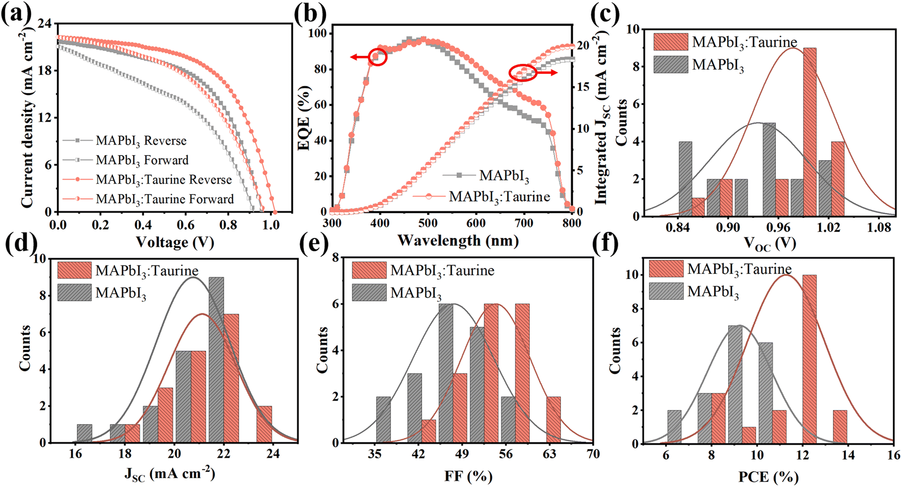
Fig. 4a shows the J–V curves of PSCs, which were scanned in forward and reverse directions, respectively. The specific PV parameters are listed in Table 2. At the forward scanning mode, the MAPbI3 device exhibited a PCE of 8.36% with a VOC of 0.92 V, a JSC of 21.10 mA cm−2, and an FF of 43.06%. In comparison, the MAPbI3:Taurine device showed a PCE of 10.64% with a VOC of 0.97 V, a JSC of 20.30 mA cm−2, and an FF of 49.44%. At the reverse scanning mode, the PCE of MAPbI3 and MAPbI3:Taurine were 11.26% and 13.19%, respectively. The hysteresis index (h) was calculated using the equation h = (PCEReverse − PCEForward)/PCEReverse to characterize the hysteresis intensity of the devices. The value of h significantly decreased from 0.262 to 0.191 with the Taurine passivation.
 | ||
| Fig. 4 (a) Forward and reverse scan J–V curves and (b) EQE spectra of MAPbI3 and MAPbI3:Taurine devices. Statistical distribution of (c) PCE, (d) VOC, (e) JSC, and (f) FF for each kind 18 devices. | ||
| Scan direction | Devices | PCE (%) | VOC (V) | JSC (mA cm−2) | FF (%) |
|---|---|---|---|---|---|
| Reverse | MAPbI3 | 11.26 | 0.96 | 21.80 | 53.80 |
| MAPbI3:Taurine | 13.19 | 1.02 | 22.30 | 57.99 | |
| Forward | MAPbI3 | 8.36 | 0.92 | 21.10 | 43.06 |
| MAPbI3:Taurine | 10.64 | 0.97 | 22.30 | 49.44 |
Fig. 4b shows the EQE spectra of the devices. The devices are identified as showing analogous spectral shapes from 300 nm to 800 nm, while the MAPbI3:Taurine device has a higher EQE in the wavelength range from 400 to 800 nm. The observed enhancement in EQE can be attributed to the improved collection and transfer of carriers resulting from the Taurine passivation. The integrated current densities are 18.37 mA cm−2 and 19.89 mA cm−2 for MAPbI3 and MAPbI3:Taurine device, respectively, which matched with the JSC from the J–V curves. To verify that Taurine is a reliable passivator to enhance the device performance, PV performance of 18 devices of each of MAPbI3 and MAPbI3:Taurine were measured, and the statistics detailed permutations are displayed in Fig. 4c–f and Table S4.† The average PCE, VOC, JSC, and FF of the control devices were 9.22 ± 1.18%, 0.94 ± 0.05 V, 20.75 ± 1.12 mA cm−2, and 47.57 ± 4.92%, respectively. After Taurine passivation, these values improved to 11.26 ± 1.30%, 0.98 ± 0.04 V, 21.12 ± 1.31 mA cm−2, and 54.37 ± 4.28%, respectively.
Taurine passivation can also enhance the device stability, the unencapsulated MAPbI3 and MAPbI3:Taurine devices were stored in ambient air with a temp. ∼25 °C and RH ∼25%. As shown in Fig. 5a, the MAPbI3:Taurine device can maintain 58.74% of its initial PCE after 720 h storage, while the MAPbI3 device can only maintain 33.98% of its original PCE. The thermal stability of the MAPbI3:Taurine and MAPbI3 devices were tested under ∼85 °C and RH ∼25% conditions. As shown in Fig. 5b, the MAPbI3:Taurine device can maintain over 33% of the original PCE, while the MAPbI3 device experienced a quick attenuation, with a 97% loss of initial value. Fig. 5d presents the MAPbI3 film and MAPbI3:Taurine film color changes, which were baked at 85 °C and RH ∼25% conditions. The MAPbI3 film was decomposed after 10 h, while the MAPbI3:Taurine film maintained a relatively dark color for up to 30 h, which is consistent with the PV performance of the devices at high temperatures. Lastly, the stability of devices against high humidity was measured at 85% RH and ∼25 °C, as shown in Fig. 5c. The MAPbI3 device was quickly decomposed in 1 h, while the MAPbI3:Taurine device maintained about 11% of the original PCE after 2.5 h. Moreover, to quantify the humidity resistance of the MAPbI3:Taurine film, the water contact angles were measured, as shown in Fig. 5e. A larger water contact angle of 65° was observed for the MAPbI3:Taurine film than that of the MAPbI3 film (44°). This could mitigate the moisture infiltration of perovskite film and thus improve the device humidity stability. The enhanced device stability was due to the decreased perovskite film trap states and the larger grain sizes of the MAPbI3:Taurine film after Taurine passivation.
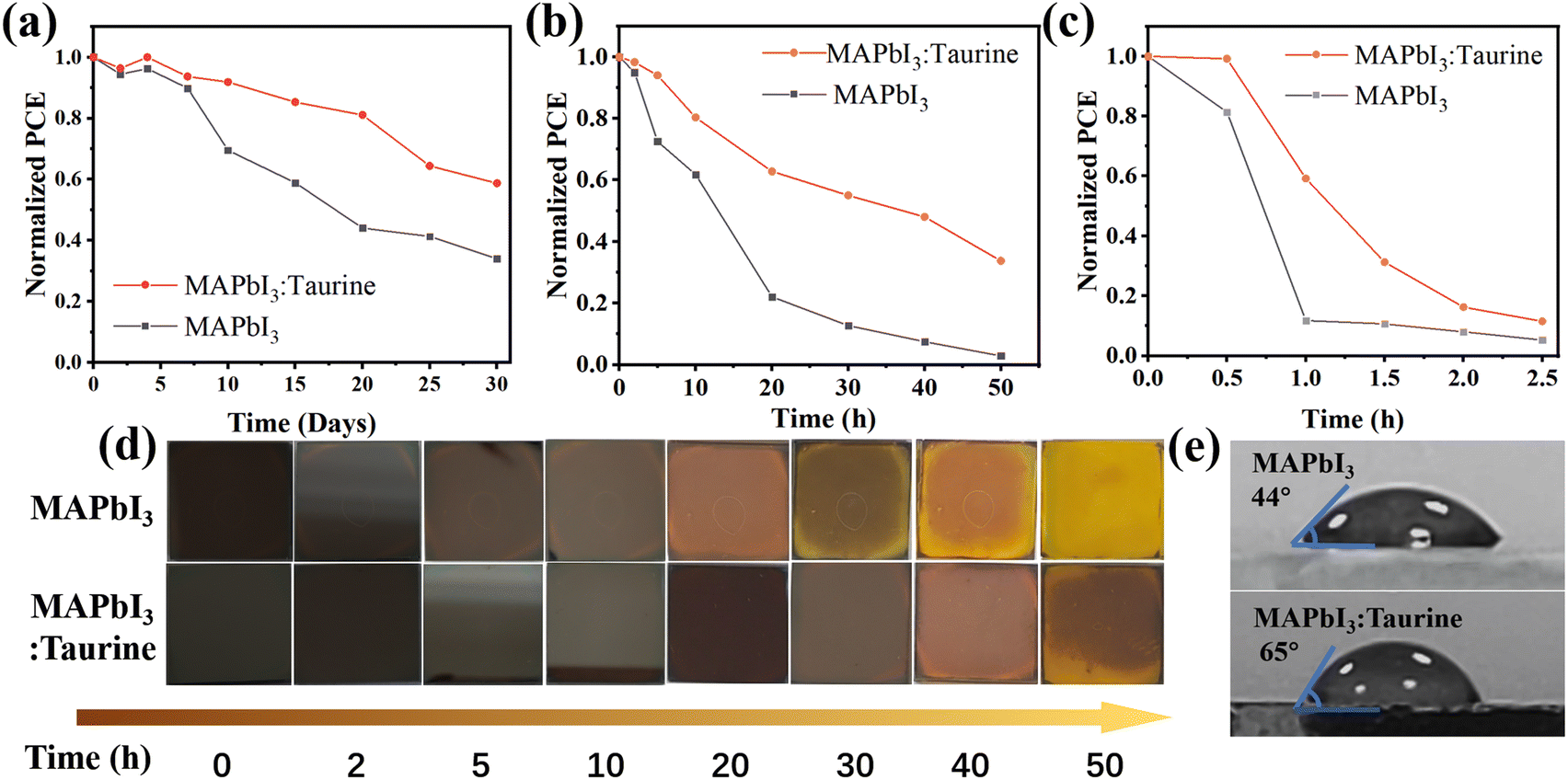 | ||
| Fig. 5 The Normalized PCE changes of MAPbI3 and MAPbI3:Taurine devices at (a) 85 °C and RH ∼25%, (b) ambient condition (∼25 °C and RH ∼25%), (c) ∼25 °C, and RH ∼85%. (d) The color changes of perovskite films under 85 °C and RH ∼25%. (e) The water contact angles of MAPbI3 and MAPbI3:Taurine perovskite films. | ||
4 Conclusions
In summary, a multifunctional Taurine molecule is introduced into MAPbI3 perovskite to passivate the defects. Taurine with –SOOOH and –NH2 groups can bind with uncoordinated Pb2+ and I− ions, respectively, which can significantly reduce the defect density, and suppress the non-radiative recombination of the carriers. The hole transport layer free PSCs with Taurine passivation showed a PCE of 13.19%, which is 17.14% higher than that of the control device (11.26%). In addition, with the suppressed defects, the Taurine passivated devices showed enhanced device stability. The unencapsulated device stored in ambient air after 720 h (temp. ∼25 °C and RH ∼25%) maintained 58.74% original PCE, while that of the control device was only about 33.98%.Author contributions
Xian Hou and Zhenjia Yuan share the first authorship. Xian Hou: investigation, formal analysis, writing – review & editing and funding acquisition; Zhenjia Yuan: theoretical investigation, data curation, analysis, and writing – original draft; Jinlong Liu and Hongzhen Ma: investigation and formal analysis; Fucheng Yu: supervision, and writing – review & editing.Conflicts of interest
There are no conflicts to declare.Acknowledgements
This work was supported by the Natural Science Foundation of Gansu Province (No. 21JR7RA264), Doctoral Scientific Research Foundation of Lanzhou University of Technology (No. 061806) and Hongliu Distinguished Young Talent Support Program Project of Lanzhou University of Technology (No. 062210).References
- https://www.nrel.gov/pv/cell-efficiency.html, accessed on May 1, 2023.
- W. Shockley and H. J. Queisser, J. Appl. Phys., 1961, 32, 510–519 CrossRef CAS.
- C. Chen, S. Zheng and H. Song, Chem. Soc. Rev., 2021, 50, 7250–7329 RSC.
- B. Boro, S. Porwal, D. Kumar, S. Mishra, S. Ghosh, S. Kansal, A. Chandra and T. Singh, Catal. Res., 2022, 2, 1–48 CrossRef.
- M. L. Sun, C. X. Zhao, J. F. Shu and X. Yin, Funct. Nanomater., 2022, 225–273 Search PubMed.
- H. Xi, Z. Song, Y. Guo, W. Zhu, L. Ding, W. Zhu, D. Chen and C. Zhang, Polym, 2022, 14, 2748 CAS.
- R. Kottayi, D. K. Maurya, R. Sittaramane and S. Angaiah, ES Energy Environ., 2022, 18, 1–40 CAS.
- S. Wang, A. Wang, X. Deng, L. Xie, A. Xiao, C. Li, Y. Xiang, T. Li, L. Ding and F. Hao, J. Mater. Chem. A, 2020, 8, 12201–12225 RSC.
- H. Kim, J. W. Lee, G. R. Han, S. K. Kim and J. H. Oh, Adv. Funct. Mater., 2021, 31, 2008801 CrossRef CAS.
- K. Zou, Q. Li, J. Fan, H. Tang, L. Chen, S. Tao, T. Xu and W. Huang, ACS Mater. Lett., 2022, 4, 1101–1111 CrossRef CAS.
- X. Zhao, T. Liu and Y. L. Loo, Adv. Mater., 2022, 34, 2105849 CrossRef CAS PubMed.
- P. Wu, S. Wang, X. Li and F. Zhang, Matte, 2022, 5, 1137–1161 CrossRef CAS.
- Z. Wang, Z. Zhang, L. Xie, S. Wang, C. Yang, C. Fang and F. Hao, Adv. Opt. Mater., 2022, 10, 2101822 CrossRef CAS.
- X. Wu, B. Wu, Z. Zhu, M. Tayyab and D. Gao, Sol. RRL, 2022, 6, 2200171 CrossRef CAS.
- T. A. Chowdhury, M. A. B. Zafar, M. S.-U. Islam, M. Shahinuzzaman, M. A. Islam and M. U. Khandaker, RSC Adv., 2023, 13, 1787–1810 RSC.
- F. Gao, Y. Zhao, X. Zhang and J. You, Adv. Energy Mater., 2020, 10, 1902650 CrossRef CAS.
- T. Bu, J. Li, F. Zheng, W. Chen, X. Wen, Z. Ku, Y. Peng, J. Zhong, Y.-B. Cheng and F. Huang, Nat. Commun., 2018, 9, 4609 CrossRef PubMed.
- S. Yang, S. Chen, E. Mosconi, Y. Fang, X. Xiao, C. Wang, Y. Zhou, Z. Yu, J. Zhao and Y. Gao, Science, 2019, 365, 473–478 CrossRef CAS PubMed.
- Q. Wang, Q. Dong, T. Li, A. Gruverman and J. Huang, Adv. Mater., 2016, 28, 6734–6739 CrossRef CAS PubMed.
- J. Yang, W. Tang, R. Yuan, Y. Chen, J. Wang, Y. Wu, W.-J. Yin, N. Yuan, J. Ding and W.-H. Zhang, Chem. Sci., 2021, 12, 2050–2059 RSC.
- K. Zhang, Y. Deng, X. Shi, X. Li, D. Qi, B. Jiang and Y. Huang, Angew. Chem., 2022, 134, e202112673 Search PubMed.
- G. Qu, D. Khan, F. Yan, A. Atsay, H. Xiao, Q. Chen, H. Xu, I. Nar and Z.-X. Xu, J. Energy Chem., 2022, 67, 263–275 CrossRef CAS.
- Y. Yang, H. Peng, C. Liu, Z. Arain, Y. Ding, S. Ma, X. Liu, T. Hayat, A. Alsaedi and S. Dai, J. Mater. Chem. A, 2019, 7, 6450–6458 RSC.
- Z. Guo, T. Gao, J. Zhuang, X. Liu, H. Guo, J. Yi, Z. Ma, H. Li and X. Cheng, ACS Appl. Energy Mater., 2021, 4, 4910–4918 CrossRef CAS.
- Y. Lei, Y. Xu, M. Wang, G. Zhu and Z. Jin, Small, 2021, 17, 2005495 CrossRef CAS PubMed.
- D. Luo, R. Su, W. Zhang, Q. Gong and R. Zhu, Nat. Rev. Mater., 2020, 5, 44–60 CrossRef CAS.
- P. Zhang, Y. Chen, S. Wu, X. Li, M. Liu and S. Li, Nanoscale, 2022, 14, 35–41 RSC.
- R. Hu, W. Hou, G. Han, T. Ou, Y. Chang and Y. Xiao, Mater. Res. Bull., 2022, 149, 111698 CrossRef CAS.
- Y. Sun, J. Zhang, H. Yu, J. Wang, C. Huang and J. Huang, Chem. Eng. J., 2021, 420, 129579 CrossRef CAS.
- W. Qiu, W. Zeng, X. Zhang, C. Li, L. Lu, X. Wang, X. Yang and B. C. Sanctuary, J. Appl. Polym. Sci., 1993, 49, 405–415 CrossRef CAS.
- J. Si, H. Sha, B. Qu, F. Wang, X. Ma, C. Jia and Y. Chen, J. Power Sources, 2022, 524, 231038 CrossRef CAS.
- S. Liu, Y. Guan, Y. Sheng, Y. Hu, Y. Rong, A. Mei and H. Han, Adv. Energy Mater., 2020, 10, 1902492 CrossRef CAS.
- Y. Li, H. Wu, W. Qi, X. Zhou, J. Li, J. Cheng, Y. Zhao, Y. Li and X. Zhang, Nano Energy, 2020, 77, 105237 CrossRef CAS.
- X. Meng, J. Deng, Q. Sun, B. Zong, Z. Zhang, B. Shen, B. Kang, S. R. P. Silva and L. Wang, J. Colloid Interface Sci., 2022, 609, 547–556 CrossRef CAS PubMed.
- W. Zhang, X. Liu, B. He, J. Zhu, X. Li, K. Shen, H. Chen, Y. Duan and Q. Tang, ACS Appl. Mater. Interfaces, 2020, 12, 36092–36101 CrossRef CAS PubMed.
- C. Xu, L. Liu, Y. Huang, F. Zhang and H. Cao, RSC Adv., 2023, 13, 2411–2417 RSC.
- J. Choi, S. J. Yang, S. G. Han, W. Sung, D. Yoo and K. Cho, Chem. Mater., 2023, 35, 1148–1158 CrossRef CAS.
- Y. Niu, D. He, X. Zhang, L. Hu and Y. Huang, Adv. Mater. Interfacesc, 2023, 10, 2201497 CrossRef CAS.
- W. Li, S. Sidhik, B. Traore, R. Asadpour, J. Hou, H. Zhang, A. Fehr, J. Essman, Y. Wang and J. M. Hoffman, Nat. Nanotechnol., 2022, 17, 45–52 CrossRef CAS PubMed.
Footnotes |
| † Electronic supplementary information (ESI) available. See DOI: https://doi.org/10.1039/d3ra02944a |
| ‡ These authors share the first authorship. |
| This journal is © The Royal Society of Chemistry 2023 |