 Open Access Article
Visible light driven reform of wasted plastics to generate green hydrogen over mesoporous ZnIn2S4†
Yeqin Zheng‡
a,
Ping Fan‡b,
Rongjie Guob,
Xiaohui Liua,
Xiantai Zhou a,
Can Xue
 *a and
Hongbing Ji
 *b
*b
aSchool of Chemical Engineering and Technology, Sun Yat-Sen University, Zhuhai, 519082, P.R. China. E-mail: xuecan@mail.sysu.edu.cn
bFine Chemical Industry Research Institute, School of Chemistry, Sun Yat-Sen University, Guangzhou, 510275, P.R. China. E-mail: jihb@mail.sysu.edu.cn
First published on 24th April 2023
Abstract
As the global consumption of plastics keeps increasing, the accumulated plastics in the natural environment have threatened the survival of human beings. Photoreforming, as a simple and low-energy way, could transform wasted plastic into fuel and small organic chemicals at ambient temperature. However, the previously reported photocatalysts have some drawbacks, such as low efficiency, containing precious or toxic metal. Herein, a noble-free, non-toxic, and easy prepared mesoporous ZnIn2S4 photocatalyst has been applied in photoreforming of polylactic acid (PLA), polyethylene terephthalate (PET) and polyurethane (PU), generating small organic chemicals and H2 fuel under simulated sunlight. Plastic was degraded into small organic molecules after the pretreatment, which futher acted as the substrate for photoreforming. Mesoporous ZnIn2S4 exhibits high H2 production efficiency, strong redox ability, and long-term photostability. Furthermore, mesoporous ZnIn2S4 could overcome the hindrances of dyes and additives of realistic wasted plastic bags and bottles with high decomposition efficiency, providing an efficient and sustainable strategy for the upcycling of wasted plastics.
Introduction
Global plastic manufacturing reached 368 million metric tons in 2019, and it is expected to rise further in the following years.1–3 Plastics generally have a relatively short service period, and most of the used plastics have become waste and accumulate in landfills or in the natural environment.4 Due to their strong chemical inertness, the spontaneous degradation process of plastic waste requires up to centuries, which will cause serious global environmental problems.5–7 Plastic pollution not only leads to a global environmental issues, but also a waste of precious resources. Most plastics are derived from fossil fuels, and it is estimated that recycling all plastic waste may save 3.5 billion barrels of oil each year.8There have been four main strategies for treating waste plastics, including landfill, incineration, mechanical and chemical recycling.9–12 Among which, incineration is widely used to treat plastic waste, generating heat energy within the combustion process, which could be further transformed to other useful energy such as electric energy.13 However, incineration needs massive energy input, high reaction temperature and the products are difficult to be separated. Therefore, developing new strategy to transform waste plastics into valuable products under mild conditions are urgently required.
Photoreforming means H2 can be generated from organic substrate and water under the sunlight with a photocatalyst.14 The photogenerated electrons from the photocatalyst can reduce water to yield H2.15 H2 is a valuable product and it has a high demand in the fields of agriculture, pharmacy, chemical industry, and renewable energy. The first example of photoreforming was TiO2/Pt photocatalyst,16 which could reform polyvinyl chloride (PVC) to H2 in water at room temperature. More recently, Reisner and co-workers reported photoreforming of real-world plastics to generate H2 and fine chemicals by CdS/CdOx17 and Ni2P|CNx.14,18 More and more photocatalyst have been developed and applied in photocatalytic conversion of wasted plastics to value-added products, such as Nb2O5,19 Ag2O/Fe-MOF,20 MoS2/CdxZn1−xS,21 etc.22–25 However, the existing photocatalysts present some disadvantages, for example, contains toxic Cd element, wide ban gap and need noble metal to generate H2. It is a big challenge to develop a noble-free, non-toxic, and high efficiency photocatalyst for photoreforming of plastics to generated H2 and other valuable products.
As a visible light-activated layered ternary metal chalcogenide photocatalyst, ZnIn2S4 possesses narrow band gap (2.28 eV), no toxic element, and simple preparation method, thus exhibits excellent performance,26 especially in the field of photocatalysis, such as pollutant removal, hydrogen evolution, and reduction of CO2.27–31 Herein, we have realized an efficient visible light driven reforming of plastic waste to H2 and small organic molecules by mesoporous ZnIn2S4. The photocatalyst mesoporous ZnIn2S4 was prepared through the low temperature hydrothermal method.29,32 Beside PET, PLA, and PU, a variety of realistic waste plastic including plastic bags and bottles could be compatible within the transformation. Compared to the reported photocatalyst, mesoporous ZnIn2S4 exhibits higher H2 production efficiency from PLA under simulated sunlight. The noble-free, simply prepared and nontoxic mesoporous ZnIn2S4 photocatalyst provides a new strategy for the sustainable upcycling of waste plastics.
Experimental section
Preparation of mesoporous ZnIn2S4
In a typical procedure,32 1.5 mmol of Zn(CH3COO)2·2H2O and 3.0 mmol of InCl3 were added into 250 mL deionized water (DI) and stirred for 30 min. After that, 8.0 mmol of thioacetamide (TAA) was added to the solution and stirred for another 30 min. The mixed solution was heated to 95 °C and refluxed for 5 h. The resulting precipitation was collected by centrifugation, rinsed with ethanol and DI water for several times, and finally re-dispersed into 100 mL of DI water. The dispersion was ultrasonicated continuously for 30 min. Mesoporous ZnIn2S4 was obtained after cryodesiccation (Scheme 1).Preparation of ZnIn2S4
ZnIn2S4 was prepared following the previous report29 with a little modified. 50 mL of glycerol was added into 200 mL H2O (pH = 2.3) and the solution was stirred for 30 min. 2.36 mmol of ZnCl2, 4.7 mmol of InCl3 and 9.4 mmol of TAA was added into the above solution. The mixture was stirred for 30 min and maintained at 80 °C for 2 h under continuous stirring. After cooling to room temperature, the product was collected by centrifugation and rinsed with ethanol several times. ZnIn2S4 was obtained after drying in a vacuum at 60 °C.Sample characterization
The crystallographic phase of the prepared sample was determined by powder X-ray diffraction (Smartlab, Rigaku). The morphologies of the prepared sample were observed by a scanning electron microscope (Zeiss, Gemini 500) and a transmission electron microscope (FEI, Tecnai G2 F30). The specific surface areas of the prepared sample were measured by nitrogen sorption at 77 K on a surface area and porosity analyzer (Micromeritics, ASAP2020M) and calculated by the Barrett–Joyner–Halenda (BJH) method. X-ray photoelectron spectroscopy (XPS) measurement was recorded on a Thermo Fisher Scientific Nexsa spectrometer (Al Kα, 1486.6 eV). The XPS spectrum was calibrated with respect to the binding energy of the adventitious C 1s peak at 284.8 eV. The UV-vis diffuse-reflectance spectrum (UV-vis DRS) was recorded with a UV-vis spectrophotometer (Shimadzu UV-3600) assembled with an optical integrated sphere using BaSO4 as the reference. Photoluminescence (PL) spectroscopy and time-resolved PL decay spectra were recorded on a spectrophotometer (Edinburgh FLS980). Electrochemical measurements were recorded on an electrochemical workstation (Chen Hua CHI660E) using a three-electrode system with a 0.5 M Na2SO4 solution as the electrolyte. A fluorine-doped tin oxide (FTO) conductive glass, the conductive side of which was coated with a thin sample film by the spin coating method, an Ag/AgCl electrode, and a platinum electrode were used as the working electrode, reference electrode, and counter electrode, respectively. Mott–Schottky analyses was measured in the dark using the impedance potential mode. Photocurrent spectral data was recorded under the manual control of ON/OFF with a 300 W xenon lamp as the excitation light source.Substrate pretreatment
In a typical procedure, the plastic samples were first frozen and crushed. Then, the aqueous KOH (2 M) and plastic power (50 mg mL−1) were added to the vial in sequence, stirring at 40 °C for 24 h. The mixture was used for photoreforming as below.Photoreforming experiments
Generally, the above solution was transferred to a 50 mL Pyrex glass photoreactor. 7.5 mg of catalyst and 2.5 mL of DI water were then added, and the final conditions were 25 mg mL−1 substrate, 5 mL of 1 M aqueous KOH and 2.5 mg mL−1 catalyst. The atmosphere of the photoreactor was replaced with N2 using an atmosphere controller (Perfect Light, AC1000). The photoreactor was irradiated by a solar light simulator (CEAULight, 150 mW cm−2) equipped with an air mass filter (AM 1.5G). All samples were kept at 25 °C with continuous stirring during irradiation for 12 h. The accumulation of H2 was analyzed by gas chromatography on an GC7900 equipped with a thermal conductivity detector using N2 as the carrier gas. The liquid product was centrifuged. The obtained supernatant 0.15 mL was mixed with D2O (0.3 mL) and maleic acid deuterium oxide solution (0.1 mL, 50 mg mL−1), which was detected by a nuclear magnetic resonance spectroscopy (Bruker AVANCE, 1H NMR) for qualitative and quantitative analysis.EPR
EPR spectra were recorded on an EPR spectrometer (JEOL, JES-FA2000). In the trapping of reactive species, a quartz flat cell (Wilmad, WG-810-A) was used to conduct the control experiments by using a free radical trapping agent DMPO.Results and discussion
Photocatalyst characterization
The scanning electron microscopy (SEM) images show that both mesoporous ZnIn2S4 (Fig. 1a) and ZnIn2S4 (Fig. 1b) have nanosheet structure. The morphology of ZnIn2S4 is flower-like hierarchical microsphere composed of plenty of nanosheet. Comparing with ZnIn2S4, mesoporous ZnIn2S4 possesses bigger pore but less agglomerated phenomena. The transmission electron microscopy (TEM) image reveals that mesoporous ZnIn2S4 have lots of pores, which were formed during cryodesiccation (Fig. 1c). Energy-dispersive spectroscopy (EDS) elemental mapping confirms that Zn (Fig. 1d), In (Fig. 1e) and S (Fig. 1f) are uniformly distributed across the mesoporous ZnIn2S4.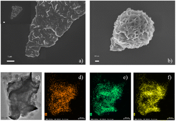 | ||
| Fig. 1 SEM images of (a) mesoporous ZnIn2S4 and (b) ZnIn2S4; TEM image of (c) mesoporous ZnIn2S4 and (d) Zn, (e) In and (f) S atom element mapping of mesoporous ZnIn2S4. | ||
XRD patterns show that the diffraction peaks of mesoporous ZnIn2S4 and ZnIn2S4 are 21.2°, 27.5° and 47.3°, corresponding to the crystal faces of (006), (102) and (110), respectively (Fig. 2d). These diffraction characteristics can be ascribed to hexagonal ZnIn2S4 (JCPDS card no. 04-009-4787). However, they show different preferred crystal faces due to the different preparation methods. XPS analysis shows that Zn 2p peaks of the mesoporous ZnIn2S4 and ZnIn2S4 appeared at 1045 and 1022.1 eV (Fig. 2a), In 3d peaks at 452.65 and 445.15 eV (Fig. 2b) and S 2p peaks at 161.9 and 163.0 eV (Fig. 2c). It suggests that mesoporous ZnIn2S4 and ZnIn2S4 have the same valence state.
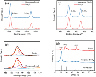 | ||
| Fig. 2 (a) Zn 2p, (b) In 3d, and (c) S 2p XPS spectra of ZnIn2S4 and mesoporous ZnIn2S4. (d) XRD profiles of ZnIn2S4 and mesoporous ZnIn2S4. | ||
The N2 adsorption–desorption isotherms curves (Fig. 3a) show that the curves of ZnIn2S4 belong to H4-type hysteresis loops, while the curves of mesoporous ZnIn2S4 belong to H3-type hysteresis loops, indicating that mesoporous ZnIn2S4 is a mesoporous material with narrow cracks and ZnIn2S4 is a slit pore material formed by the accumulation of lamellar particles, which is consistent to the result of SEM images. Besides, pore size distribution plots confirm that the pores of mesoporous ZnIn2S4 are bigger than ZnIn2S4 (Fig. 3b), which affect the efficiency of photoreforming of plastics.
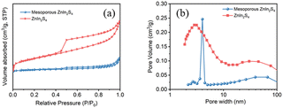 | ||
| Fig. 3 (a) N2 adsorption–desorption isotherms and (b) pore size distribution plots of ZnIn2S4 and mesoporous ZnIn2S4. | ||
Photophysical and electrochemical properties of the photocatalysts play an important role in the photocatalytic activity.33 The UV-vis diffuse-reflectance spectrum (UV-vis DRS) shows that both mesoporous ZnIn2S4 and ZnIn2S4 can absorb visible light, and the absorption edge of mesoporous ZnIn2S4 (λedge = 554 nm) is located at longer wavelength than that of ZnIn2S4 (λedge = 516 nm), which suggest the possibility of high photocatalytic activity of the above materials under visible light (Fig. 4a). To explore the energy band structures of the photocatalyst, Tafel plots and Mott–Schottky plots were performed. According to Tafel plots, the band-gap energy of mesoporous ZnIn2S4 and ZnIn2S4 were 2.19 eV and 2.32 eV respectively, which indicate that mesoporous ZnIn2S4 is more efficient for visible-light utilization than ZnIn2S4 (Fig. 4a, inset). Furthermore, Mott–Schottky plots suggest that the two photocatalyst are n-type semiconductors and the flat-band potentials of the mesoporous ZnIn2S4 and ZnIn2S4 are −0.91 V (vs. Ag/AgCl) and −0.94 V (vs. Ag/AgCl), respectively (Fig. 4b and c). Thus, the valence band (VB) of photocatalyst could be calculated from the band-gap energy (mesoporous ZnIn2S4: 1.28 eV, ZnIn2S4: 1.38 eV). Photocurrent measurements were also conducted to study the ability and stability on the photogenerated charges of mesoporous ZnIn2S4 and ZnIn2S4. As shown in Fig. 4d, mesoporous ZnIn2S4 is stronger and more stable than ZnIn2S4 on the photocurrent response, which indicates the photogenerated charges ability of mesoporous ZnIn2S4 is better.
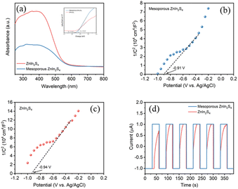 | ||
| Fig. 4 (a) UV-vis DRS, inset: Tauc plot of samples; Mott–Schottky curves of (b) mesoporous ZnIn2S4 and (c) ZnIn2S4; (d) transient photocurrent response of samples. | ||
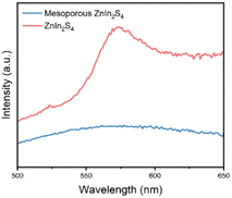
Typically, fluorescence spectroscopy is used to characterize the separation efficiency of photogenerated electron hole pairs.34 PL spectra of mesoporous ZnIn2S4 and ZnIn2S4 were recorded at an excitation wavelength of 405 nm (Fig. 5). ZnIn2S4 shows a strong fluorescence emission peak at 490 nm, while the fluorescence emission peak of mesoporous ZnIn2S4 were nearly quenched, which indicate that the recombination of electrons and holes of mesoporous ZnIn2S4 was greatly hindered.
Photorefroming of plastics
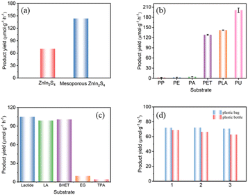
The photoreforming performances of as-prepared photocatalysts were evaluated by the hydrogen production of plastics reforming experiments. All conditions, including photocatalyst concentration, substrate concentration and reaction time, were optimized for maximal the H2 production (Fig. S1†). In a typical procedure, plastics were pretreated in aqueous KOH at 40 °C with continuous stirring for 24 h in the dark. After pretreatment, the photocatalyst was added to the above solution, and the mixture was then transferred to a Pyrex flask, purged with N2 and irradiated by simulated sun light (AM 1.5G, 150 mW cm−2) at room temperature for certain time.As for PLA, mesoporous ZnIn2S4 exhibits higher hydrogen production efficiency than ZnIn2S4, which was 143.6 μmol g−1 h−1 and 70.4 μmol g−1 h−1 respectively (Fig. 6a). The different performances of the two photocatalyst might be attributed to the differences of the morphology and pores distribution, and the lamellar structure and mesopores in mesoporous ZnIn2S4 make it exhibit better hydrogen production efficiency. Compared with previous reports, the H2 yield from photoreforming of PLA by mesoporous ZnIn2S4 is almost eight times higher than that over CdS/CdOx and CNx/NiP (Table 1), while from PET is 3-fold higher than CdS/CdOx and 14-fold higher than CNx/NiP, which shows superior H2 production efficiency.
| Catalyst | Yield (μmolH2 gsub−1) | Reference | |
|---|---|---|---|
| PLA | PET | ||
| a Reaction conditions: pretreated PLA or PET (25 mg mL−1) with all catalyst except CNx|Ni2P (which used 50 mg mL−1), KOH or NaOH (aq. 5 mL), catalyst (1.5 mg mL−1), measurements taken after 20 h of simulated sunlight (AM 1.5 G, 100 mW cm−2, rt).b CNx|Ni2P (1.6 mg mL−1).c CdS/CdOx (1 nmol). | |||
| Mesoporous ZnIn2S4 | 412.1 | 472.3 | This work |
| ZnIn2S4 | 356.6 | 177.7 | This work |
| CNx|Ni2Pb | 59.7 ± 6.0 | 33.1 ± 1.7 | 14 |
| CdS/CdOxc | 54.1 ± 8.9 | 132 ± 6 | 17 |
Mesoporous ZnIn2S4 was further employed to a variety of common polymers under simulated sun light. Polypropylene (PP), polyethylene (PE) and polyacrylic acid (PA) could only produce trace amount of hydrogen (H2), while PET, PLA and polyurethane (PU) performance well, and the order of H2 production efficiency was PP < PE < PA < PET < PLA < PU under the same reaction conditions (Fig. 6b). As pretreated with aqueous KOH, the ester group of PET, PLA and PU might be partly decomposed under base environment, and the residue would partial dissolve in the solutions for further photoreforming. It is might be the reason why PET, PLA and PU shows higher H2 production and degradation efficiency than those of PP, PE and PA.
As for the realistic plastic wastes, which always contain dyes, additives and many kinds of impurities, might make them more difficult to be photocatalytic degradation than the pure one. To evaluate the performance of the real-world plastics over mesoporous ZnIn2S4, the photoreforming of plastic bags and plastic bottle were conducted. As shown in Fig. 6d, the H2 production efficiency from realistic plastic bag and plastic bottle were achieved respective in 72.2 μmol g−1 h−1 and 68.9 μmol g−1 h−1 under the same conditions for the photocatalytic degradation in Fig. 6b. The main component of plastic bags and bottles are PLA and PET, respectively. Comparing the results presented in Fig. 6b with 6d, the additives within the plastic bags and bottles hindered their photoreforming performances significantly.
1H NMR and 13C NMR spectra (Fig. S2†) of the liquid phase product of PLA after photoreforming for 12 h indicate that PLA was decomposed into small organic molecules, such as lactic acid (LA), by mesoporous ZnIn2S4 under simulated sun light. Some of LA were further oxidized to pyruvic acid. As shown in Fig. S3,† PET was transferred into ethylene glycol (EG) and terephthalate (TPA) after the pretreatment, and the oxidation product of EG, acetic acid and 2-hydroxyacetic acid were detected in the liquid phase product, showing that mesoporous ZnIn2S4 has strong oxidation capacity. The quantitative analysis results showed that the lactic acid in the solution after pretreatment was approximately 28.3 mg, while after photoreforming the amount of LA increased to 61.7 mg with 4.4 mg of pyruvic acid. Combining the result of Fig. S1(b),† it indicated that lactic acid was generated after the pretreatment with KOH, which was further oxidized into valuable small organic molecules by mesoporous ZnIn2S4 during the photoreforming. Besides, there is no CO2 detected during the process.
The monomers and dimers of PLA and PET, including lactic acid (LA), lactide, ethylene glycol (EG), terephthalate (TPA) and bis(2-hydroxyethyl) terephthalate (BHET), were further applied to investigate the photoreforming mechanism over mesoporous ZnIn2S4. As shown in Fig. 6c, the H2 yield from LA (105.0 μmol g−1 h−1) and lactide (99.0 μmol g−1 h−1) were close to that from PLA (142.8 μmol g−1 h−1), which indicate that mesoporous ZnIn2S4 could decompose the ester group and further oxidize the monomers derived from PLA to pyruvic acid. As for the monomer and dimer of PET, the H2 yield from EG (9.6 μmol g−1 h−1) and TPA (4.1 μmol g−1 h−1) was much lower than that from PET (129.7 μmol g−1 h−1), and the H2 yield from BHET (100.8 μmol g−1 h−1) was close to that from PET. It is might cause that mesoporous ZnIn2S4 could decompose the ester group of PET and BHET, but the oxidation ability of mesoporous ZnIn2S4 is not enough for EG or TPA. The liquid phase product of monomers and dimers of PLA and PET were analyzed by 1H NMR and 13C NMR as shown in Fig. S4 and S5.†
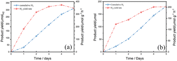
To evaluate the photostability of mesoporous ZnIn2S4 in aqueous KOH, a long-term photoreforming of PLA and PET were conducted. According to the result, the H2 yield from PLA kept raising from the first day to the fourth day, it is because more and more PLA were dissolved in the solution and decomposed into oligomers and monomers for further photoreforming. While in the last day, the H2 production rate went down a little bit which was limited by the total amount of substrate in the solution (Fig. 7a). As for PET, the H2 yield kept raising from the first day to the end. The total amount of H2 yield from PET is less than that from PLA after photoreforming for 5 days and the fastest H2 yield rate from PET is slower than from PLA (Fig. 7b). It is probably because the monomers of PET, EG and TPA, are difficult to be oxidized by mesoporous ZnIn2S4, which limits the H2 yield from PET.
Mechanism investigation
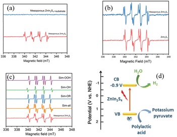
To investigate the mechanism of photoreforming of plastics, electron paramagnetic resonance (EPR) measurement was conducted to test free radicals,35 which were trapped by dimethyl pyrroline oxide (DMPO, radical scavenger). PLA was used as the model substrate, reformed by mesoporous ZnIn2S4 under a N2 atmosphere. Without substrate, hydroxyl radical (·OH) and superoxide radical (·OOH) could be detected when the mixture was irradiated by simulated sun light (Fig. 8a), which suggest that mesoporous ZnIn2S4 could generate not only electron–hole pairs, but also free radicals with strong oxidation. When the pretreated PLA solution was added into the above solution, all free radicals disappeared, which suggest that PLA could combine with the free radicals, then the oxidation reactions occurred. As shown in Fig. 8b, when mesoporous ZnIn2S4 and ZnIn2S4 irradiated by the simulated sun light, there were no significant difference in the EPR spectra.Combine with the results as shown above and references,14,17,32 the mechanism of photoreforming of plastics over mesoporous ZnIn2S4 is proposed as following: mesoporous ZnIn2S4 could absorbs simulated sun light, generating electron–hole pairs and free radicals. Depolymerization and oxidation reaction of PLA would take place with the combined action of hole and free radicals generated from mesoporous ZnIn2S4. PLA was decomposed to oligomers and monomer and further oxidized to pyruvic acid. At the meantime, H2O combined with the electrons on the surface of the photocatalyst could generate pure hydrogen through reduction reaction. Through the above reactions, plastic have been depolymerized into small organic molecules and produce pure H2.
Conclusions
In this work, we have realized the recycling and utilization of plastic waste through the green and environmental-friendly photorefroming over mesoporous ZnIn2S4. PLA, PET and PU were firstly depolymerized into oligomers and monomers with the help of KOH. And driven by the visible light, oligomers could be depolymerized into small organic molecules, which was further oxidized by mesoporous ZnIn2S4 at room temperature with hydrogen generated. The strong redox ability, efficient separation of photogenerated electron hole pairs and long-term photostability of the catalyst promoting the reforming of plastics in high efficiency. Albeit hindered by dyes and additives, the plastic bags and bottles could also be reformed efficiently. No carbon dioxide was detected during the photocatalytic process. The noble-free, easy-preparation and non-toxic ZnIn2S4 photocatalyst provides an efficient and sustainable strategy for the plastic waste upcycling.Author contributions
Yeqin Zheng: data curation, software, investigation, visualization, writing – review & editing. Ping Fan: methodology, investigation, writing-original draft, validation, formal analysis. Rongjie Guo: validation. Xiaohui Liu: validation. Xiantai Zhou: resources. Can Xue: conceptualization, resources, validation, writing – review & editing, funding acquisition. Hongbing Ji: resources, review, funding acquisition.Conflicts of interest
There are no conflicts to declare.Acknowledgements
This work was financially supported by the National Key Research and Development Program Nanotechnology Specific Project (No. 2020YFA0210900), National Natural Science Foundation of China (No. 21908256, 21938001).References
- X. Chen, Y. Wang and L. Zhang, ChemSusChem, 2021, 14, 4137–4151 CrossRef CAS PubMed.
- H. Li, H. A. Aguirre-Villegas, R. D. Allen, X. Bai, C. H. Benson, G. T. Beckham, S. L. Bradshaw, J. L. Brown, R. C. Brown, V. S. Cecon, J. B. Curley, G. W. Curtzwiler, S. Dong, S. Gaddameedi, J. E. García, I. Hermans, M. S. Kim, J. Ma, L. O. Mark, M. Mavrikakis, O. O. Olafasakin, T. A. Osswald, K. G. Papanikolaou, H. Radhakrishnan, M. A. S. Castillo, K. L. Sánchez-Rivera, K. N. Tumu, R. C. V. Lehn, K. L. Vorst, M. M. Wright, J. Wu, V. M. Zavala, P. Zhou and G. W. Huber, Green Chem., 2022, 24, 8899–9002 RSC.
- R. A. Sheldon and M. Norton, Green Chem., 2020, 22, 6310–6322 RSC.
- R. Geyer, J. R. Jambeck and K. L. Law, Sci. Adv., 2017, 3, e1700782 CrossRef PubMed.
- W. Cornwall, Science, 2021, 373, 36–39 CrossRef CAS PubMed.
- M. MacLeod, H. P. H. Arp, M. B. Tekman and A. Jahnke, Science, 2021, 373, 61–65 CrossRef CAS PubMed.
- K. L. Law and R. C. Thompson, Science, 2014, 345, 144–145 CrossRef CAS PubMed.
- A. Rahimi and J. M. García, Nat. Rev. Chem., 2017, 1, 0046 CrossRef.
- K. Ragaert, L. Delva and K. Van Geem, Waste Manage., 2017, 69, 24–58 CrossRef CAS PubMed.
- J. M. Garcia and M. L. Robertson, Science, 2017, 358, 870–872 CrossRef CAS PubMed.
- S. Ügdüler, K. M. V. Geem, R. Denolf, M. Roosen, N. Mys, K. Ragaert and S. D. Meester, Green Chem., 2020, 22, 5376–5394 RSC.
- D. D. Pham and J. Cho, Green Chem., 2021, 23, 511–525 RSC.
- D. P. Serrano, J. Aguado and J. M. Escola, ACS Catal., 2012, 2, 1924–1941 CrossRef CAS.
- T. Uekert, H. Kasap and E. Reisner, J. Am. Chem. Soc., 2019, 141, 15201–15210 CrossRef CAS PubMed.
- S. Chu, B. Zhang, X. Zhao, H. S. Soo, F. Wang, R. Xiao and H. Zhang, Adv. Energy Mater., 2022, 12, 2200435 CrossRef CAS.
- T. Kawai and T. Sakata, Chem. Lett., 1981, 10, 81–84 CrossRef.
- T. Uekert, M. F. Kuehnel, D. W. Wakerley and E. Reisner, Energy Environ. Sci., 2018, 11, 2853–2857 RSC.
- T. Uekert, M. A. Bajada, T. Schubert, C. M. Pichler and E. Reisner, ChemSusChem, 2021, 14, 4190–4197 CrossRef CAS PubMed.
- X. Jiao, K. Zheng, Q. Chen, X. Li, Y. Li, W. Shao, J. Xu, J. Zhu, Y. Pan, Y. Sun and Y. Xie, Angew. Chem., Int. Ed., 2020, 59, 15497–15501 CrossRef CAS PubMed.
- J. Qin, Y. Dou, F. Wu, Y. Yao, H. R. Andersen, C. Hélix-Nielsen, S. Y. Lim and W. Zhang, Appl. Catal., B, 2022, 319, 121940 CrossRef CAS.
- Y. Li, S. Wan, C. Lin, Y. Gao, Y. Lu, L. Wang and K. Zhang, Sol. RRL, 2021, 5, 2000427 CrossRef CAS.
- I. Nabi, A.-U.-R. Bacha, K. Li, H. Cheng, T. Wang, Y. Liu, S. Ajmal, Y. Yang, Y. Feng and L. Zhang, iScience, 2020, 23, 101326 CrossRef CAS PubMed.
- B. Cao, S. Wan, Y. Wang, H. Guo, M. Ou and Q. Zhong, J. Colloid Interface Sci., 2022, 605, 311–319 CrossRef CAS PubMed.
- M. Han, S. Zhu, C. Xia and B. Yang, Appl. Catal., B, 2022, 316, 121662 CrossRef CAS.
- C. Xing, G. Yu, J. Zhou, Q. Liu, T. Chen, H. Liu and X. Li, Appl. Catal., B, 2022, 315, 121496 CrossRef CAS.
- J. Wang, S. Sun, R. Zhou, Y. Li, Z. He, H. Ding, D. Chen and W. Ao, J. Mater. Sci. Technol., 2021, 78, 1–19 CrossRef CAS.
- D. Yuan, M. Sun, S. Tang, Y. Zhang, Z. Wang, J. Qi, Y. Rao and Q. Zhang, Chin. Chem. Lett., 2020, 31, 547–550 CrossRef CAS.
- J. Qiu, M. Li, L. Yang and J. Yao, Chem. Eng. J., 2019, 375, 121990 CrossRef CAS.
- C. Jiang, H. Wang, Y. Wang and H. Ji, Appl. Catal., B, 2020, 277, 119235 CrossRef CAS.
- R. M. Mohamed, A. Shawky and M. S. Aljahdali, J. Taiwan Inst. Chem. Eng., 2016, 65, 498–504 CrossRef CAS.
- C. Chen, W. Hou and Y. Xu, Appl. Catal., B, 2022, 316, 121676 CrossRef CAS.
- L. Huang, B. Han, X. Huang, S. Liang, Z. Deng, W. Chen, M. Peng and H. Deng, J. Alloys Compd., 2019, 798, 553–559 CrossRef CAS.
- L. Zhang, J. Ran, S.-Z. Qiao and M. Jaroniec, Chem. Soc. Rev., 2019, 48, 5184–5206 RSC.
- S. Zhang, H. Gao, X. Liu, Y. Huang, X. Xu, N. S. Alharbi, T. Hayat and J. Li, ACS Appl. Mater. Interfaces, 2016, 8, 35138–35149 CrossRef CAS PubMed.
- Z. Wang, W. Ma, C. Chen, H. Ji and J. Zhao, Chem. Eng. J., 2011, 170, 353–362 CrossRef CAS.
Footnotes |
| † Electronic supplementary information (ESI) available. See DOI: https://doi.org/10.1039/d3ra02279j |
| ‡ These authors contributed equally to this work. |
| This journal is © The Royal Society of Chemistry 2023 |


