
 Open Access Article
 This Open Access Article is licensed under a Creative Commons Attribution-Non Commercial 3.0 Unported Licence
Facile synthesis of a MOF-derived Co–N–C nanostructure as a bi-functional oxygen electrocatalyst for rechargeable Zn–air batteries†
Xinlei Luo‡
a,
Ziheng Zheng‡a,
Bingxue Houb,
Xianpan Xie*a and
Cheng Cheng Wang *a
*a
aSchool of Entrepreneurship and Innovation, Shenzhen Polytechnic, Shenzhen, 518055, China. E-mail: xxp@szpt.edu.cn; wangchengcheng@szpt.edu.cn
bAviation Engineering Institute, Civil Aviation Flight University of China, Guanghan, 618037, China
First published on 21st June 2023
Abstract
A novel catalyst obtained from the pyrolysis of a Co/Fe/Zn zeolitic imidazolite framework was prepared as an oxygen reduction reaction (ORR) and oxygen evolution reaction (OER) electrocatalyst. The Co–N–C-900 catalyst displays promising ORR and OER activity with E1/2 = 0.854 V and Ej=10 = 1.780 V. The rechargeable Zn–air battery equipped with a Co–N–C-900 cathode electrocatalyst illustrates a high peak power density of 275 mW cm−2, which is much superior than that of commercial 20% Pt/C. Significantly, the designed Zn–air battery with the Co–N–C-900 catalyst presents good cycling stability for 180 h in the rechargeable Zn–air battery.
1 Introduction
Zinc–air batteries have attracted more attention recently because of their promising energy density, safety and low cost.1–4 The oxygen reduction reaction (ORR) and oxygen evolution reaction (OER) are inhibited due to slow kinetics and high overpotential.5 So far, Pt, IrO2 and RuO2 have been identified as some of the most efficient ORR and OER electrocatalysts. However, their high price and scarcity have limited their commercialization for rechargeable zinc–air batteries.6 It is essential to develop non-platinum electrocatalysts to replace Pt electrocatalysts such as carbon nanomaterials and so on. Non-Pt metal-doped into carbon (NPMC) electrocatalysts are regarded as some of the most practicable electrocatalysts due to their low cost, high electronic conductivity and excellent electrochemical performance.7–12NPMC electrocatalysts M–N–C (M = Fe or Co)1–13 have been widely studied as efficient oxygen electrocatalysts. ORR activity can be largely improved by introducing Co into nitrogen doped carbon due to more active sites.14,15 Therefore, carefully designing Co–N–C materials is desirable for obtaining electrocatalysts with promising electrochemical performance. MOFs are excellent candidates for metal carbon composites due to a great variety of compositions including metal ions and organic ligands. Zeolitic imidazolate frameworks (ZIFs) are reckoned as precursors due to C, N, and transition metals. Recent years, some researchers are paying more attention to apply Co–N–C electrocatalysts prepared by ZIFs structure in the fields of Zn–air battery. Rui Hao studied21 trimetallic zeolitic imidazolite frameworks-derived Co nanoparticles@CoFe–nitrogen-doped porous carbon as bi-functional electrocatalysts for Zn–air battery, and they found that Co@CoFe–N–C catalysts displayed desirable ORR and OER activity. Zn–air battery equipped with Co@CoFe–N–C catalyst could exhibit high power density of 174.1 mW cm−2 and outstanding stability of 100 h. J. Tan22 also did some further study on the Co, ZIF-8 derived Co–N–C with high ORR performance and it was used as a support to disperse OER active Ni3Fe nanoparticles. At current densities of 10 mA cm−2 for OER, potentials were 1.54 V and potentials were 0.79 V at current densities of 3 mA cm−2 for ORR, respectively. Rechargeable Zn–air battery assembled with Ni3Fe/Co–N–C exhibited superior efficiency and excellent durability. Although extensive efforts were made due to preparation of Co–N–C electrocatalysts in the aspects of Zn–air battery, some organic solvents and surfactants were still used in the study, which could lead to waste and environmental pollution.
In this study, ZIFs structure were used because of its high nitrogen/carbon contents, high microporous surface area, tunable pore texture, and highly dispersed metal sites after thermal decomposition. It is widely known that Co–N–C was extensively studied to identify ORR and OER electrocatalytic performance. In the present study, in order to make the preparation process easier and scalable, water was innovatively only used as solvents in facile preparation of Co–N–C electrocatalysts in this study. Results showed that Co–N–C catalyst fired at 900 °C in N2 atmosphere exhibited high ORR activity with E1/2 of 0.854 V under O2-saturated 0.1 M KOH, which was comparable with commercial Pt/C from JM (Johnson Matthey) under the same testing condition. Moreover, regarding to OER activity, it also showed comparable current density and onset potential. Assembled initial Zn–air battery by Co–N–C exhibited relatively stable charging and discharging cycle stability for more than 180 h. This work opens light on a promising technique to prepare Co–N–C electrocatalysts and enhance its application of rechargeable zinc–air battery.
2 Experimental
2.1 Catalysts preparation
Firstly, ZnSO4·7H2O, and CoSO4·7H2O were all ordered from Sigma-Aldrich. Certain mole ratio of ZnSO4·7H2O, and CoSO4·7H2O, was mixed with 30 mL distilled water. Secondly, 2-methylimidazole (2-mim) was added into the solution equipped with stirring for 24 h at room temperature. Thirdly, the solution was centrifuged with water for three times by 6000 rpm and dried at 60 °C in oven. Fourthly, the precursor was fired at 800 °C and 900 °C for 3 h in the presence of N2 atmosphere. Moreover, powders were etched as far as possible with 0.5 M H2SO4 at 80 °C for 12 h for twice, and washed with water. Samples obtained were named as Co–N–C-800, Co–N–C-900, Co–N–C-900–acid, respectively. KOH was ordered from Beijing Chemical Reagent Company. Nafion solution (5%) was purchased from Alfa Company. Pure argon and oxygen was used for carbonization and electrochemical performance tests. For comparison, Pt/C and IrO2 electrocatalyst (20 wt%, Johnson Matthey) were used.2.2 Catalysts characterizations
XRD technique was used to characterize the phase of prepared samples (Bruker D8 Advances) in step scan mode of 10–80° (2θ) for 0.02°. XPS technique was tested by using ESCALAB 250Xi instrument from Thermo Fisher. TEM and element mapping analysis were conducted by Titan G2 60-300 electron microscope.2.3 Electrochemical characterizations
Standardized three-electrode method was used to test electrochemical performances from Princeton electrochemical workstation. Firstly, inks were prepared by mixing 5 mg electrocatalysts and 800 mL ethanol–200 mL isopropyl alcohol–Nafion composite solutions, Secondly, 10 mL inks were dipped on glassy carbon disc electrode with diameter of 5 mm. Pt wire and saturated calomel electrode (SCE) were regarded as counter electrode and reference electrode, respectively. Oxygen gas (99.9%) was purged for 30 min before tests.For ORR tests, linear scan voltammetry (LSV) was tested from 0 to −1 V (vs. RHE) at 10 mV s−1 in oxygen saturated 0.1 M KOH from 400 rpm to 2500 rpm with the same loading. For OER tests, LSV was conducted from 0 to 1 V (vs. RHE) at 10 mV s−1 at 1600 rpm in oxygen saturated 0.1 M KOH. IR correction and corrected curves including LSV were already done, which were shown in the previous paper.17 Pt/C and IrO2 from Johnson Matthey (Pt/C-JM) were studied for ORR and OER under the same condition. Potentials were given with RHE reference electrode (ERHE = Evs. SCE + ESCE + 0.059 × pH, ESCE = 0.247 V at 20 °C).
2.4 Cell assemble and tests
Catalyst inks were prepared as above and it was distributed uniformly on carbon cloth with Ni-foam as current collector. Then, carbon cloth (cathode) and polished zinc plate (anode) were assembled in Zn–air battery by 6 M KOH including 0.2 M ZnCl2. Zn–air battery tests were done by LAND CT2001A testing device. Charge and discharge data were obtained at 5 mA cm−2. Polarization curves for discharge process were drawn by CHI6000A at 0.5 mA s−1.3 Results and discussion
3.1 Characterization of electrocatalysts
Fig. 1a indicates XRD patterns for Co–N–C precursors before firing. It can be clearly seen that it showed well defined diffraction peaks that were corresponding to MOFs (JCPDS no. 15-0806). After firing at 800 °C, the majority peaks were Co3ZnC (JCPDS no. 89-7242), ZnO (JCPDS no. 74-0534) and C (JCPDS no. 80-0017), in which it could indicate that the sintering temperature was not high enough to make ZnO evaporate (Fig. 1b). Fig. 1c and d clearly illustrates that Co3ZnC disappeared completely, indicating that ZIF-8 changed into Co–N–C structure. | ||
| Fig. 1 XRD patterns of as-prepared Co–N–C precursor (a), Co–N–C-800 (b), Co–N–C-900 (c), and Co–N–C-900–acid (d) catalysts. | ||
SEM was used to identify Co–N–C precursor's morphology and Co–N–C catalysts' morphology. According to Fig. 2a, it can be shown that the size of rhombic dodecahedron shaped ZIF-8 was 300 nm. After firing at 800 °C, the surface of the particles became quite rough, and there were some tiny particles covering. Moreover, the surface of Co–N–C-900 particles (Fig. 2e and f) looked differently from that of Fig. 2c and d. It is also worth mentioning that there was no huge difference of Co–N–C-900–acid catalysts compared to that Co–N–C-900 particles (Fig. 2g and h). It can be seen from our results, the shape of the nanoparticles was rhombus, however, in this recent published paper, it illustrated that a novel nanocapsules with cobalt core and nitrogen-doped carbon shells (Co@NC) supported on MOFs-derived hierarchical porous carbon framework.16 By rationally controlling the size and mesoporous ratio, can they obtain promising electrochemical performance. It is worthwhile for us to do further study regarding to our experiment.
 | ||
| Fig. 2 SEM image of as-prepared Co–N–C precursor (a and b), Co–N–C-800 (c and d), Co–N–C-900 (e and f), and Co–N–C-900–acid catalysts (g and h). | ||
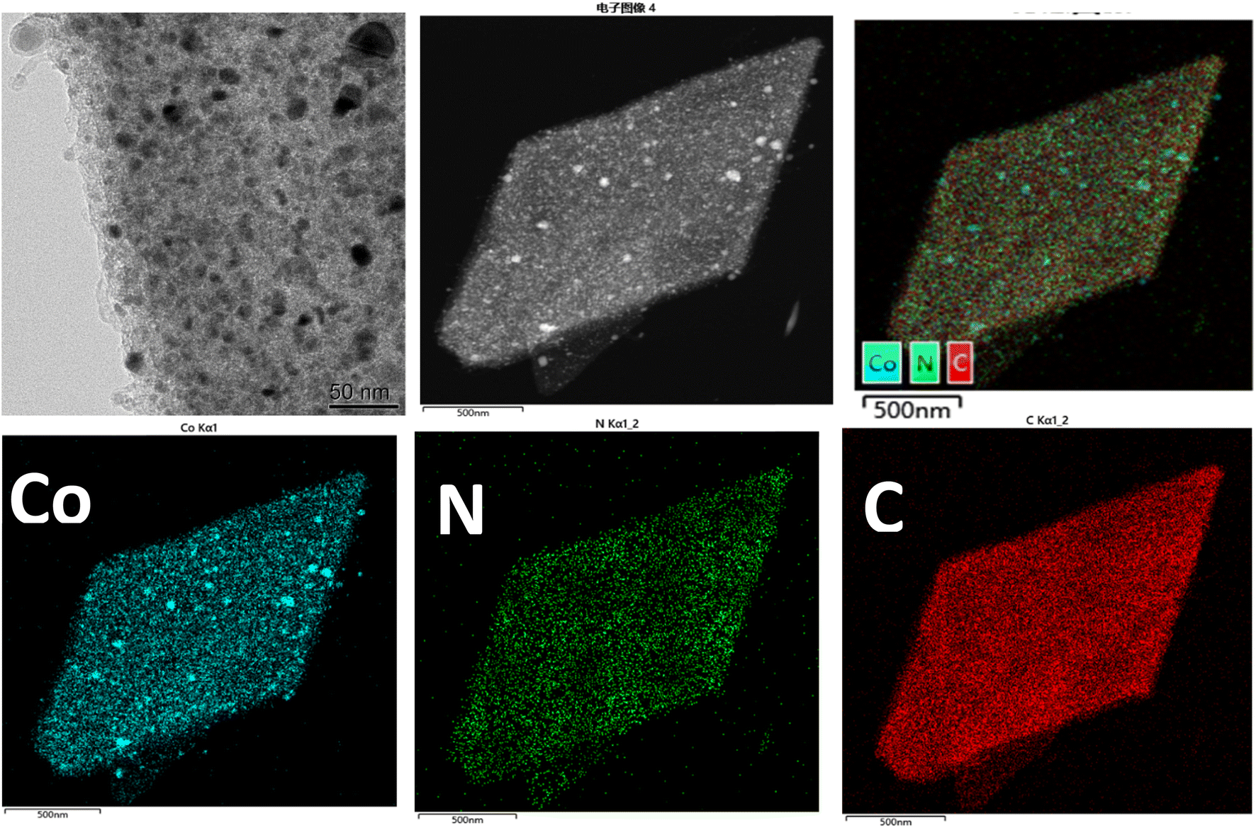
Fig. 3 showed TEM images of Co–N–C-900 catalysts. Only rhombic structure can be observed from high magnification pictures. Elemental mapping in TEM clearly shows that C, N and Co elements were distributed homogeneously in the structure. Fig. S2† also showed TEM images of Co–N–C-900–acid catalysts. Elemental mapping in TEM shows that Co, C, N elements were distributed in the structure. Cobalt existed in Co–N–C-900 catalysts in a highly dispersed state. The composition of Co–N–C-900 and Co–N–C-900–acid catalysts were further investigated by XPS. Fig. 4 shows selected survey scan of catalysts after heat-treated at 900 °C, indicating the presence of Co, O, N and C elements of Co–N–C-900 and Co–N–C-900–acid catalysts. Obviously, there were no differences compared to these two catalysts, in which might illustrate that acid wash did not show obvious effect on the composition of catalysts in this study. In order to identify the assumption, the deconvolution of Co 2p and N 1s in Co–N–C-900 and Co–N–C-900–acid catalysts was shown in Fig. 5b–e. Co0, Co2+ and Co3+ were deconvoluted in this study and Table 1.
 | ||
| Fig. 3 TEM images and EDS mapping of selected Co–N–C-900 catalysts. | ||
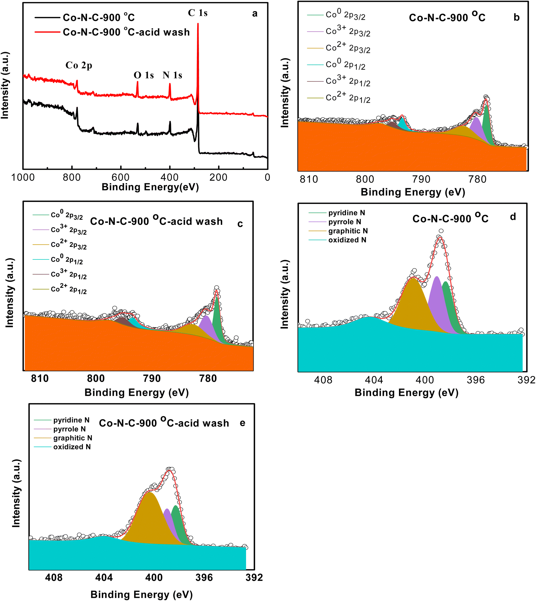 | ||
| Fig. 4 XPS of Co–N–C-900 and Co–N–C-900–acid catalysts (a), high resolution of Co 2p (b and c), N 1s (d and e) of Co–N–C-900 and Co–N–C-900–acid catalysts. | ||
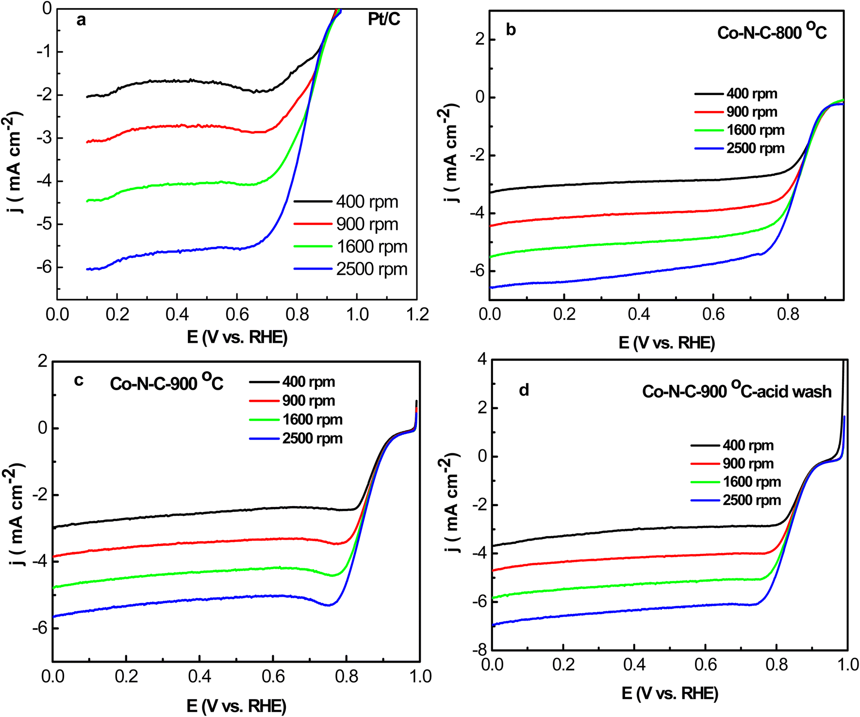 | ||
| Fig. 5 Liner sweep voltammetry (LSV) of Pt/C (a), Co–N–C-800 (b), Co–N–C-900 (c) and Co–N–C-900–acid (d) catalysts for oxygen reduction in O2-saturated 0.1 M KOH at various rotation speeds and scan rate of 5 mV s−1. | ||
| Total atomic N% | Pyridinic N | Pyrrole N | Graphitic N | Oxidized N | |
|---|---|---|---|---|---|
| Co–N–C-900 | 8.21 | 23.26% | 24.97% | 38.24% | 13.54% |
| Co–N–C-900–acid wash | 12.17 | 18.91% | 17.26% | 50.95% | 12.88% |
Table 1 lists the calculated results of N after deconvolution. 8.21% and 12.17% of N could account for the whole electrocatalysts. It can also be seen that pyridinic N, pyrrole N, graphitic N and oxidized N were all deconvoluted for two electrocatalysts. According to previous results, the relatively higher content of graphitic N of Co–N–C–acid wash electrocatalyst was desirable due to conveying higher positive charge density near carbon atoms and improving current density by benefiting oxygen adsorption and weakening of oxygen to oxygen bonds. Furthermore, pyridinic and pyrrole nitrogen could cooperate with cobalt to form Co–Nx. It was more active than nitrogen doped carbon materials for ORR. Table 2 lists the calculated results of Co0, Co2+ and Co3+ after deconvolution. It can be shown that 1.88% and 1.46% of Co can account for the whole electrocatalysts. Moreover, for Co–N–C-900 catalysts, the atomic ratio of Co0, Co2+ and Co3+ was nearly the same. While, for Co–N–C-900–acid wash catalysts, the atomic ratio of Co0 was more than that of Co2+ and Co3+.
| Total atomic Co% | Co0 | Co2+ | Co3+ | |
|---|---|---|---|---|
| Co–N–C-900 | 1.88 | 33.84% | 32.49% | 33.66% |
| Co–N–C-900–acid wash | 1.46 | 40.14% | 33.77% | 26.09% |
According to the XPS deconvolution results of Co and elemental mapping results of Co–N–C-900, we might make an assumption that heterointerfaces existed in the electrocatalyst, and it is also widely known that heterointerfaces can significantly improve not only the electrocatalytic activity and stability but also the ionic conductivity of heterostructure electrolytes and increasing the durability of heterostructure electrodes with faster oxygen exchange kinetics at the heterointerfaces. Such improvements can be credited to many factors, containing lattice strain, dislocation, cation segregation, changes in electronic structure, and expansion of triple phase boundaries. It has been reported that the atomic structure of the heterointerfaces such as local strain and dislocations can extremely influence the ionic conductivity and/or the electrocatalytic activity of the heterostructure.17
3.2 The electrochemical performance of Co–N–C catalysts
ORR activity of Co–N–C-800, Co–N–C-900, Co–N–C-900–acid and Pt/C electrodes were studied by LSV measurements under O2 saturated 0.1 M KOH at 10 mV s−1 from 400 rpm to 2500 rpm (Fig. 5). It can be easily seen that onset potential and half-wave potential of Co–N–C-800 were 0.95 V and 0.834 V. Moreover, Co–N–C-900 exhibited much better ORR performance including onset potential (0.98 V) and half-wave potential (0.854 V). And it was 20 mV more positive than Co–N–C-800, which shows that relatively obvious effects of the sintering temperature of catalysts. However, onset potential and half-wave potential varied less due to acid wash. For Co–N–C-900–acid, they were 0.8 V and 0.844 V, respectively (Fig. 5d). Half-wave potential of Co–N–C-900 was 140 mV more positive than commercial Pt/C-JM (0.84 V) with the same loading.ORR kinetics of Co–N–C-800, Co–N–C-900, Co–N–C-900–acid and Pt/C electrocatalysts were investigated by K–L curves (Fig. S3†). Results indicated that all samples exhibited low peroxide yield and approximately electron transfer number of 4. 4e− reduction was dominant in the ORR activity of Co–N–C-800, Co–N–C-900, Co–N–C-900–acid and Pt/C. In order to compare electrochemical performance of ORR activity of these electrocatalysts, Fig. S4† lists the comparison of onset potential and current density of Co–N–C-800, Co–N–C-900, Co–N–C-900–acid and Pt/C, in which illustrate that Co–N–C-900 exhibited relatively higher ORR performance in total.
OER activity of Co–N–C-800, Co–N–C-900, Co–N–C-900–acid and IrO2 was also evaluated under O2-saturated 0.1 M KOH at 10 mV s−1 at 1600 rpm (Fig. 6). Onset potential of Co–N–C-900 was 1.58 V, which was 60 mV higher than IrO2 (1.52 V). Maximum current density measured at 1.9 V was 22.5 mA cm−2, which was higher than IrO2 (9 mA cm−2). Remarkably, Co–N–C-900 afforded current density (10 mA cm−2) at 1.81 V, while Co–N–C-800 afforded current density (10 mA cm−2) at 1.85 V, which was higher than that Co–N–C-800. IrO2 afforded current density (10 mA cm−2) at 1.98 V. Fig. 7 lists the comparison of ORR and OER activity of these Co–N–C-800, Co–N–C-900, Co–N–C-900–acid electrocatalysts under the same condition for the sake of clearly identifying the electrochemical performance, and it can clearly identify that higher sintering temperature (900 °C) could lead to better ORR and OER performance of Co–N–C electrocatalysts. One of the main reasons that could lead to relatively higher ORR and OER performance was probably due to the electron transfer to adsorb oxygen catalysis species was improved, the oxygen exchange rate was accelerated, and are the real active sites of the electrocatalytic OER and ORR processes.18–20
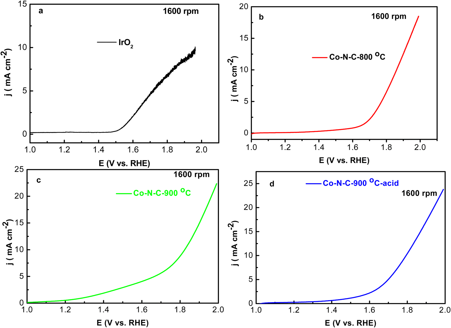 | ||
| Fig. 6 Liner sweep voltammetry (LSV) of IrO2 (a), Co–N–C-800 (b), Co–N–C-900 (c) and Co–N–C-900–acid (d) catalysts for oxygen evolution in O2-saturated 0.1 M KOH at various rotation speeds and scan rate of 5 mV s−1 with 1600 rpm rotation rate. | ||
 | ||
| Fig. 7 ORR and OER potential difference curves of Co–N–C-800 (a), Co–N–C-900 (b) and Co–N–C-900–acid (c) catalysts in O2-saturated 0.1 M KOH with 1600 rpm and scan rate of 5 mV s−1. | ||
3.3 Cell performance
Co–N–C-900 electrocatalyst assembled in aqueous rechargeable Zn–air battery was tested. Three Zn–air batteries could power LED screen continuously (Fig. 8). OCVs of Co–N–C-900-based Zn–air battery was 1.376 V. Co–N–C-900-based Zn–air battery achieved maximum peak power density of 275 mW cm−2.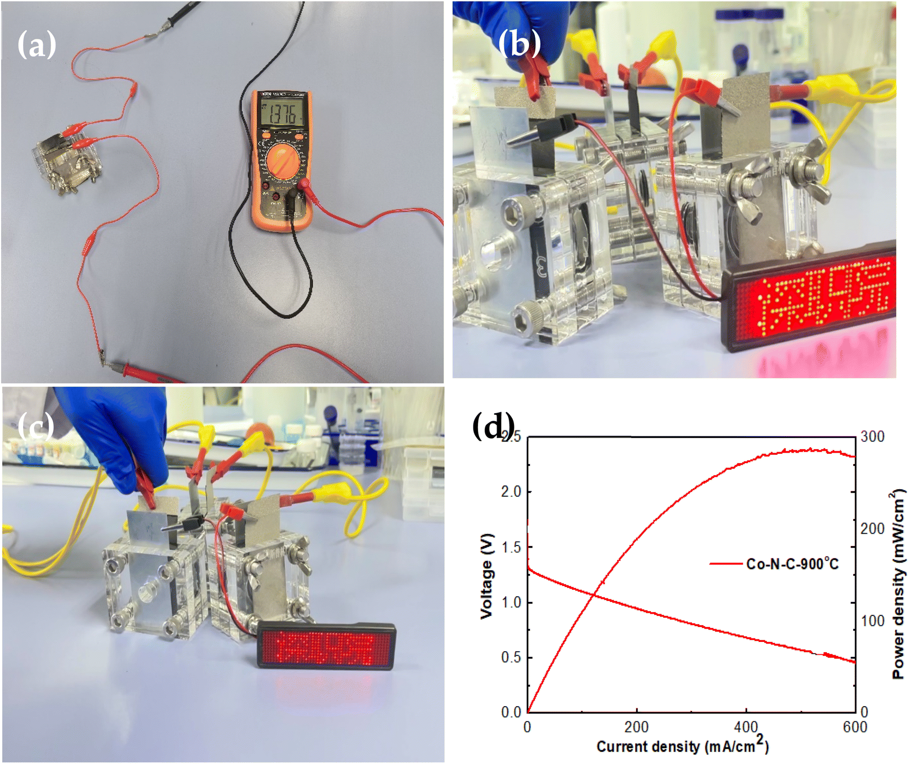 | ||
| Fig. 8 (a) OCV for three Co–N–C-900 assembled Zn–air batteries. (b and c) Power supplying for LED. (d) I–V–P curves of curve of Co–N–C-900 assembled Zn–air battery. | ||
The stability of rechargeable Co–N–C-900-based Zn–air battery was tested by charging and discharging for 10 min individually with repeated cycles at 5 mA cm−2, as shown in Fig. 9. Its voltage gap (Δη) was 1.1 V initially, and the voltage gap changed to 0.8 V after operating for 50 h. After 180 hours, voltage gap decreased to 0.8 V and the voltage gap was quite stable, respectively. This results can be comparable with what other researchers have published recently.23 Such phenomenon might be due to irreversible Zn plating–stripping process. Co–N–C-900-based Zn–air battery exhibits good recharge ability, and its performance is comparable to other results tested in our study. Moreover, Co–N–C-900 electrocatalyst is cheaper than IrO2 and Pt/C, in which shows its high economic potential.
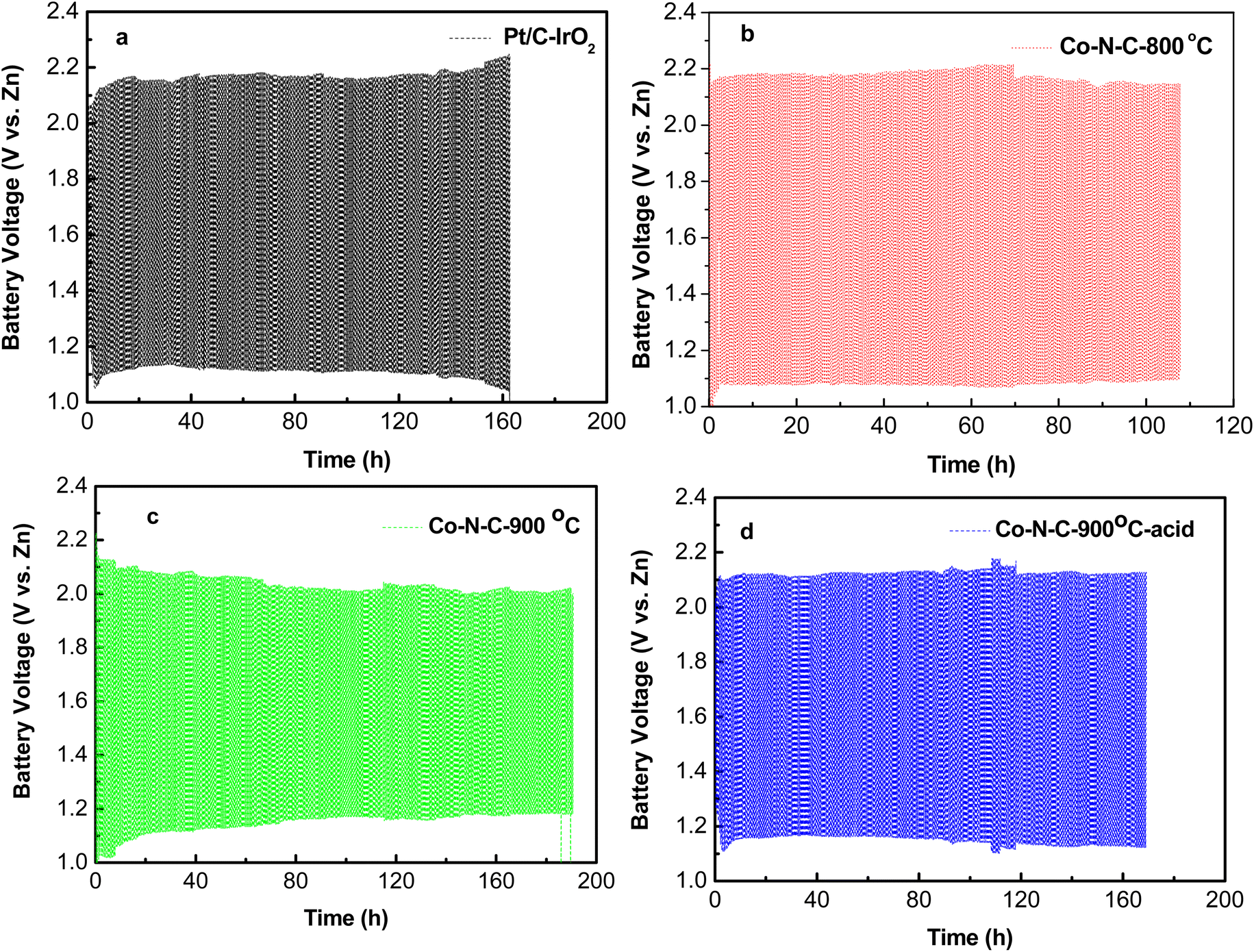 | ||
| Fig. 9 Galvanostatic charge–discharge profiles of Zn–air batteries at 5 mA cm−2. (a) Pt/C–IrO2 assembled, Co–N–C-800 assembled (b), Co–N–C-900 assembled (c), Co–N–C-900–acid assembled (d). | ||
4 Conclusions
Optimized amount of Co–N–C electrocatalyst from metal–organic frameworks were easily prepared in this study. Co–N–C-900 electrocatalysts have been reckoned as one of best non-precious metal catalysts, exhibiting onset potential and half-wave potential of 0.98 V and 0.854 V, which was more superior than that of Pt/C catalysts. Moreover, rechargeable Zn–air battery exhibited stable charging and discharging potential gap at 5 mA cm−2 with high cycling stability of more than 180 h, respectively. This work achieved the rational design and precise preparation of Co-based NPMC catalyst, and it also made a step for fabrication of highly pure and active electrocatalyst for rechargeable zinc–air battery applications.Conflicts of interest
There are no conflicts to declare.Acknowledgements
The authors acknowledge the facilities, the scientific and technical assistance of Hoffman Advanced Materials Research Institute from Shenzhen Polytechnic. The authors also acknowledge the supports 2022 Research Funding of Shenzhen Polytechnic (6022310007K), 2022 Shenzhen Science and Technology Program (GJHZ20210705142006020) and Sichuan Science and Technology Program (2020YJ0501, 2022YFH0044).References
- X. Liu, et al., Integrating NiCo Alloys with Their Oxides as Efficient Bifunctional Cathode Catalysts for Rechargeable Zinc-Air Batteries, Angew. Chem., Int. Ed. Engl., 2015, 54(33), 9654–9658 CrossRef CAS PubMed.
- G. Wu, et al., High-performance electrocatalysts for oxygen reduction derived from polyaniline, iron, and cobalt, Science, 2011, 332(6028), 443–447 CrossRef CAS PubMed.
- K. Gong, et al., Nitrogen-doped carbon nanotube arrays with high electrocatalytic activity for oxygen reduction, Science, 2009, 323(5915), 760–764 CrossRef CAS PubMed.
- M. Lefevre, et al., Iron-based catalysts with improved oxygen reduction activity in polymer electrolyte fuel cells, Science, 2009, 324(5923), 71–74 CrossRef CAS PubMed.
- F. Jaouen, et al., Recent advances in non-precious metal catalysis for oxygen-reduction reaction in polymer electrolyte fuel cells, Energy Environ. Sci., 2011, 4(1), 114–130 RSC.
- Z. Chen, et al., A review on non-precious metal electrocatalysts for PEM fuel cells, Energy Environ. Sci., 2011, 4(9), 3167–3192 RSC.
- H. T. Chung, J. H. Won and P. Zelenay, Active and stable carbon nanotube/nanoparticle composite electrocatalyst for oxygen reduction, Nat. Commun., 2013, 4, 1922 CrossRef PubMed.
- S. Gupta, et al., Bifunctional Perovskite Oxide Catalysts for Oxygen Reduction and Evolution in Alkaline Media, Chem.–Asian J., 2016, 11(1), 10–21 CrossRef CAS PubMed.
- G. Wu, et al., Carbon nanocomposite catalysts for oxygen reduction and evolution reactions: from nitrogen doping to transition-metal addition, Nano Energy, 2016, 29, 83–110 CrossRef CAS.
- Y. Cheng, et al., A class of transition metal-oxide@MnOx core–shell structured oxygen electrocatalysts for reversible O2 reduction and evolution reactions, J. Mater. Chem. A, 2016, 4(36), 13881–13889 RSC.
- Y. Cheng, et al., Structurally confined ultrafine NiO nanoparticles on graphene as a highly efficient and durable electrode material for supercapacitors, RSC Adv., 2016, 6(56), 51356–51366 RSC.
- Y. Cheng, et al., Iron Oxide Nanoclusters Incorporated into Iron Phthalocyanine as Highly Active Electrocatalysts for the Oxygen Reduction Reaction, ChemCatChem, 2018, 10(2), 475–483 CrossRef CAS.
- Z. Liu, et al., In Situ Exfoliated, Edge-Rich, Oxygen-Functionalized Graphene from Carbon Fibers for Oxygen Electrocatalysis, Adv. Mater., 2017, 29(18), 1606207 CrossRef PubMed.
- S. Cai, et al., 3D Co-N-doped hollow carbon spheres as excellent bifunctional electrocatalysts for oxygen reduction reaction and oxygen evolution reaction, Appl. Catal., B, 2017, 217, 477–484 CrossRef CAS.
- Y. Liang, et al., Metal–polydopamine frameworks and their transformation to hollow metal/N-doped carbon particles, Nanoscale, 2017, 9(16), 5323–5328 RSC.
- G. Zhou, et al., MOFs-derived hierarchical porous carbon supported Co@NC nanocapsules for pH universal oxygen reduction reaction and Zn-air batteries, Appl. Surf. Sci., 2023, 621, 156906 CrossRef CAS.
- K. Chhetri, et al., Engineering the abundant heterointerfaces of integrated bimetallic sulfide-coupled 2D MOF-derived mesoporous CoS2 nanoarray hybrids for electrocatalytic water splitting, Mater. Today Nano, 2022, 17, 100146 CrossRef CAS.
- D. R. Paudel, et al., Multi-interfacial dendritic engineering facilitating congruous intrinsic activity of oxide-carbide/MOF nanostructured multimodal electrocatalyst for hydrogen and oxygen electrocatalysis, Appl. Catal., B, 2023, 331, 122711 CrossRef CAS.
- K. Chhetri, et al., Integrated hybrid of graphitic carbon-encapsulated CuxO on multilayered mesoporous carbon from copper MOFs and polyaniline for asymmetric supercapacitor and oxygen reduction reactions, Carbon, 2021, 179, 89–99 CrossRef CAS.
- S.-M. Ji, et al., Metal-organic framework assisted vanadium oxide nanorods as efficient electrode materials for water oxidation, J. Colloid Interface Sci., 2022, 618, 475–482 CrossRef CAS PubMed.
- R. Hao, J. Chen, Z. Wang, Y. Huang, P. Liu, J. Yan, K. Liu, C. Liu and Z. Lu, Trimetallic Zeolitic imidazolite framework-derived Co nanoparticles@CoFe-nitrogen-doped porous carbon as bifunctional electrocatalysts for Zn-air battery, J. Coll. Interface Sci., 2021, 586, 621–629 CrossRef CAS PubMed.
- J. Tan, T. Thomas, J. Liu, L. Yang, L. Pan, R. Cao, H. Shen, J. Wang, J. Liu and M. Yang, Rapid microwave-assisted preparation of high-performance bifunctional Ni3Fe/Co-N-C for rechargeable Zn-air battery, Chem. Eng. J., 2020, 395, 125151 CrossRef CAS.
- G. Zhou, X. Yan, T. Zhang, K. Wang, J. Zhang and J. Guo, MOFs-derived hierarchical porous carbon supported Co@NC nanocapsules for pH universal oxygen reduction reaction and Zn-air batteries, Appl. Surf. Sci., 2023, 621, 156906 CrossRef CAS.
Footnotes |
| † Electronic supplementary information (ESI) available. See DOI: https://doi.org/10.1039/d3ra02191b |
| ‡ The authors are making the same contribution to this paper. |
| This journal is © The Royal Society of Chemistry 2023 |