
 Open Access Article
 This Open Access Article is licensed under a Creative Commons Attribution-Non Commercial 3.0 Unported Licence
Real-time observation of ion exchange dynamics during surface treatment of all-inorganic perovskite quantum dots with Zn-halogenide complexes for color tuning and enhanced quantum efficiency†
Egle Ezerskyte,
Martynas Malikenas ,
Simas Sakirzanovas,
Arturas Katelnikovas and
Vaidas Klimkevicius*
,
Simas Sakirzanovas,
Arturas Katelnikovas and
Vaidas Klimkevicius*
Institute of Chemistry, Faculty of Chemistry and Geosciences, Vilnius University, Naugarduko 24, LT-03225 Vilnius, Lithuania. E-mail: vaidas.klimkevicius@chf.vu.lt
First published on 10th May 2023
Abstract
All-inorganic lead perovskite quantum dots (QDs), due to their distinctive optical properties, have become one of the “hottest” topics in materials science; therefore, the development of new QD synthesis methods or their emission color adjustment is of great interest. Within this study, we present the simple preparation of QDs employing a novel ultrasound-induced hot-injection method, which significantly reduces the QD synthesis time from several hours to merely 15–20 minutes. Moreover, the post-synthesis treatment of perovskite QDs in solutions using zinc halogenide complexes could increase the QD emission intensity and, at the same time, boost their quantum efficiency. This behavior is due to the zinc halogenide complex's ability to remove or significantly reduce the number of surface electron traps in perovskite QDs. Finally, the experiment that shows the ability to instantly adjust the desired emission color of perovskite QDs by variation of the amount of added zinc halogenide complex is presented. The instantly obtained perovskite QD colors cover virtually the full range of the visible spectrum. The zinc halogenide modified perovskite QDs exhibit up to 10–15% higher QEs than those prepared by an individual synthesis.
Introduction
Due to outstanding photoelectric performance and other excellent optical properties, the halogenide perovskite quantum dots (QDs) became one of the most studied materials to be applied in solar cells1 and other optoelectronic devices including light-emitting diodes,2 photocatalysts,3 photodetectors,4–6 and lasers.7 Among these materials, the all-inorganic metal halide perovskite CsPbX3 (where X = I, Br, Cl) QDs show superior thermal and photostability.8 In the past decade, there have been thousands of publications dedicated to the perovskite QD structure–property relationships and their application in various optoelectronic fields.9,10 The first inorganic lead perovskite QD synthesis employing the hot-injection method was reported in 2015.1 Since then, the demand for novel, easier, and faster perovskite QD synthesis methods has gradually increased. Many alternative approaches toward perovskite QD synthesis were recently reported in the literature.12 The alternative methods for perovskite QDs preparation could be classified as follows: microwave-assisted,13,14 solvothermal,15 sonochemical,16,17 and precipitation-based methods.18–21 Among all these methods, the hot-injection synthesis approach, initially reported by Kovalenko et al.,11 remains the most used. Despite the popularity of the hot-injection method, it is time-consuming and requires separate synthesis to obtain the perovskite QDs with the desirable emission wavelengths. Furthermore, recent studies showed that the perovskite QDs emission color could be varied by the post-synthesis treatment of the QDs. For instance, Milstein et al. described the perovskite QDs surface post-synthesis treatment using trimethyl silyl halogenides or benzoyl halogenides.22 Akkerman et al.,23 on the other hand, reported the modification of cesium lead bromide QDs using various alkylammonium halogenides. Such modification resulted in a desired emission color change of QDs; however, the recorded photoluminescence quantum efficiencies (PLQE) after the treatment were lower than the initial values of CsPbBr3 QDs. It is important to note that PLQEs of perovskite QDs depend on the surface defect amount. The halide vacancies are the most abundant due to their low formation energy or higher trapping ability.24,25 The vacancies induced by Cs or Pb are less favorable and could be removed using lead halogenide adlayers26,27 or other salts (potassium, sodium, cesium oleates28,29). Moreover, there are many techniques that can reduce the surface electron traps caused by halogenide vacancies, including passivation with organic–inorganic hybrid ion pair didodecyl dimethylammonium sulphide,30 alkylammonium halide,24 zinc salts,31 trioctylphosphine oxide (TOPO),32 thiocyanate salts,33 even perfluorodecanoic acid,34 etc. However, despite the intensive studies in the recent literature, the development of novel synthesis techniques that allow simple preparation and/or post-synthesis modification of the obtained perovskite QDs, tailoring the optical properties, and boosting PLQEs remains in high demand.In this study, we propose the novel ultrasound-induced hot-injection method for all-inorganic perovskite QDs synthesis along with the successive surface modification utilizing zinc halogenide complexes and tuning perovskite QDs emission intensity and quantum efficiency (QE) due to reduced surface electron traps. In addition, the evolution of QDs emission colors covering virtually the full range of visible spectrum during the surface treatment of CsPbBr3 QDs, obtained from a sole synthesis, is also discussed in detail.
Experimental
Materials
Cesium carbonate (Cs2CO3, Acros Organics, 99.99%, Geel, Belgium), lead(II) bromide (PbBr2, Alfa Aesar, 99.998%, Haverhill, MA, USA), zinc chloride (ZnCl2 anhydrous, Alfa Aesar, 98%, Haverhill, MA, USA), zinc bromide (ZnBr2 anhydrous, Alfa Aesar, 98%, Haverhill, MA, USA), zinc iodide (ZnI2, ultra-dry, Alfa Aesar, 99.995%, Haverhill, MA, USA), (toluene C7H8, Avantor, HPLC grade, Gliwice, Poland), 1-octadecene (ODE, Alfa Aesar, 90% tech. grade, Haverhill, MA, USA), oleylamine (OAm, Acros Organics, 80–90%, Geel, Belgium) and oleic acid (OA, Alfa Aesar, 90% tech. grade, Haverhill, MA, USA) were used as received.Preparation of Cs-oleate
Cs-oleate was prepared according to the procedure published elsewhere;11 briefly, Cs2CO3 (0.407 g, 1.25 mmol) was loaded into a 50 mL 3-neck flask along with 1-octadecene (18.75 mL), and oleic acid (1.25 mL). The mixture was firstly heated for 1 hour at 120 °C under reduced pressure (ca. 10–15 mbar) and then heated under argon at 150 °C until the transparent solution was obtained. Please note that Cs-oleate precipitates out of ODE at room temperature; thus, it has to be pre-heated to 120 °C before the injection.Preparation of ZnX2-oleylamine complex solutions (X = Cl, Br, I)
For the post-synthesis ion exchange procedure, zinc complexes in toluene were prepared as follows: the 0.6 mmol of anhydrous zinc halogenides (81.8 mg of ZnCl2, 135.1 mg of ZnBr2 or 192.5 mg of ZnI2) were dissolved in a mixture of dry toluene (20 mL) and oleylamine (OAm, 400 μL) under stirring at room temperature.Synthesis of CsPbBr3 QDs
All inorganic perovskite QDs synthesis was performed according to a recently published procedure.35 Briefly, 0.376 mmol PbBr2 (138.0 mg) was dispersed in a mixture of oleic acid (1 mL), oleylamine (1 mL), and 1-octadecene (10 mL). The reaction vessel of the precursor solution was purged with argon for 5 minutes and subjected to a tip-sonicator (SonoPuls HD 3100, Bandelin (max power 70 W), Berlin, Germany). The synthesis temperature was monitored by a thermocouple wire. The mixture was preheated to 120 °C using ultrasound with non-pulse mode and with a nominal power of ca. 40 W. The temperature inside the reaction vessel was maintained at 120 °C until the complete dissolution of precursors (ca. 10 minutes). The ultrasound power was then raised to 60 W, and the reaction mixture was heated to 160 °C. Once this temperature was reached, the preheated Cs-oleate solution (0.8 mL, 0.05 mmol) was injected. After five seconds, the ultrasound tip was removed, and the mixture of the formed lead perovskite QDs was cooled down to room temperature by emerging the vessel into the ice bath. The precipitates were collected by centrifugation (Megafuge 16R, Thermo Scientific, Waltham, MA, USA) at 6000 rpm for 10 minutes. Next, the collected QDs were re-dispersed in toluene (20 mL), and the obtained dispersions were further centrifuged at 2000 rpm for five minutes to remove the large aggregates. Finally, the collected supernatant was 5-fold diluted with toluene and used for further QDs investigation as a stock solution. The synthesis scheme is summarized in Fig. 1.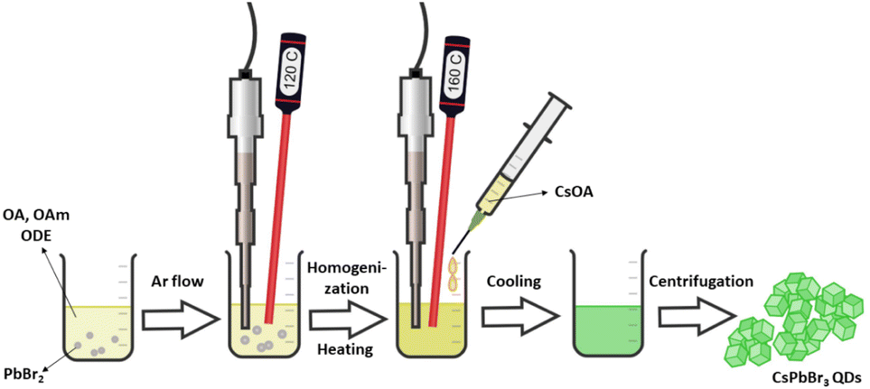 | ||
| Fig. 1 The synthesis scheme of all-inorganic perovskite QDs. | ||
Surface modification procedure
To modify the QDs surface, aliquots (5 to 500 μL) of a freshly prepared ZnX2(OAm)2 (X = Cl, Br, I) complex were added to a stock solution of CsPbBr3 QDs (4 mL) under stirring at ambient conditions. The real-time ion exchange dynamics, the change in emission spectra as a function of time after ZnCl2(OAm)2 or ZnI2(OAm)2 complex solutions were added to the CsPbBr3 QDs stock solutions, was measured. This experiment was conducted using a Miniature Spectrometer FLAME-S-UV-Vis (OceanOptics, Orlando, FL, USA). The samples were excited with a 5 mW 405 nm wavelength laser diode. The solutions were magnetically stirred (500 rpm) throughout the entire experiment. The emission spectra in the 200–850 nm range were measured every 50 ms up to 10 minutes and later processed using OceanOptics SpectraSuite software. It should be noted that for experiments requiring lower amounts, the aliquots of CsPbBr3 QDs stock solutions and ZnX2-oleylamine complexes (X = Cl, Br, I) were recalculated proportionally.Analysis of the synthesized CsPbX3 QDs
XRD patterns of the synthesized all-inorganic perovskite CsPbBr3 QDs were recorded using a Rigaku MiniFlexII diffractometer (Rigaku, Tokyo, Japan) working in a Bragg–Brentano focusing geometry. The scanning speed was 5° min−1. FEI Tecnai F20 X-TWIN transmission electron microscope (TEM) (FEI Company, Hillsboro, OR, USA) with 200 kV accelerating voltage was used to determine the size and shape of the synthesized perovskite QDs. The images were taken using a Gatan Orius CCD camera (Gatan, Leicester, UK). Absorption spectra were measured on a PerkinElmer Lambda 35 UV/Vis spectrometer (PerkinElmer, Waltham, MA, USA) in the range of 350–800 nm. Emission spectra of CsPbBr3 perovskite QDs were recorded on the Edinburgh Instruments FLS980 spectrometer (Edinburgh Instruments, Livingston, UK) equipped with double excitation and emission monochromators, a 450 W Xe arc lamp, a cooled (253 K) single-photon counting photomultiplier (Hamamatsu R928P, Hamamatsu Photonics K.K., Hamamatsu, Japan) in a standard quartz cell (l = 10 mm). The photoluminescence emission spectra were corrected for instrument response by a correction file obtained from a tungsten incandescent lamp certified by NPL (National Physics Laboratory, UK). For recording PL decay curves, a hydrogen-filled pulsed nano flash lamp nF920 was used as an excitation source. Before the measurements, the obtained QDs stock solutions were diluted with toluene (1![[thin space (1/6-em)]](https://www.rsc.org/images/entities/char_2009.gif) :10 v/v) to avoid undesirable reabsorption due to the high optical density. The quantum efficiencies (QE) of the prepared samples were determined by an integrating sphere method and calculated according to the following equation:
:10 v/v) to avoid undesirable reabsorption due to the high optical density. The quantum efficiencies (QE) of the prepared samples were determined by an integrating sphere method and calculated according to the following equation:
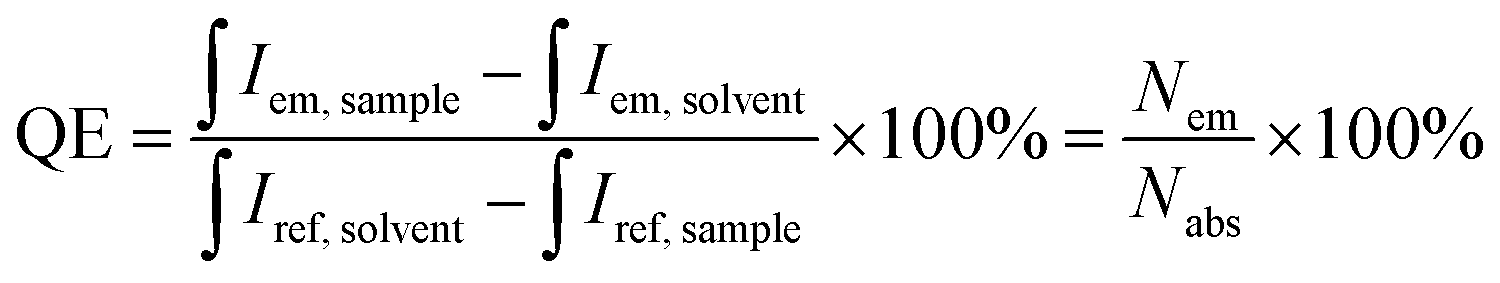 | (1) |
 and
and  are the integrated emission of sample and solvent, respectively; and
  are the integrated reflectance of sample and solvent, respectively; Nem and Nabs represent the number of emitted and absorbed photons, respectively.
Results and discussion
The all-inorganic perovskite QDs with a general formula CsPbBr3 were synthesized via ultrasound-induced hot-injection synthesis method. In this method, the acceleration of precursors dissolution or homogenization, as well as the increase of reaction mixture temperature, is driven by high-frequency ultrasound. As our group showed before,35 the employment of high-frequency ultrasound could reduce the CsPbBr3 synthesis duration from several hours to merely 15–20 minutes if compared to the conventional hot-injection method.11 The XRD analysis revealed that the synthesized CsPbBr3 QDs crystallize in an orthorhombic crystal structure (space group Pmna, #53). The recorded XRD patterns match well with the reference pattern of CsPbBr3 (#96-153-3063) (Fig. 2a), indicating that single-phase materials were obtained. Please note that only two strong reflection peaks are visible in the sample XRD pattern due to out-of-plane measurement, as was also described by Toso et al.36 The orthorhombic CsPbBr3 unit cell along the standard orientation of crystal shape is presented in Fig. 2b. At daylight, the CsPbBr3 QDs in toluene possess a vibrant yellow-greenish color (Fig. 2c) and exhibit bright green emission under UV excitation (λex = 365 nm) (Fig. 2d). Fig. 2e shows the recorded emission spectra of all inorganic CsPbBr3 QDs in toluene. The emission band of CsPbBr3 QDs is symmetric with a relatively narrow line width full width at half maxima (FWHM) = 21.5 nm (0.104 eV) with a maximum at 512 nm. The photoluminescence decay curve of CsPbBr3 QDs is plotted in Fig. 2f. The calculated average PL lifetime was 6.4 ns and corresponded well with the data presented in the literature.11 The TEM image of CsPbBr3 QDs is given in Fig. 2g. It is evident that the synthesized CsPbBr3 QDs are uniform with a rigid cubic morphology. Furthermore, the given TEM image was used to determine the QDs size distribution by employing ImageJ software (v. 1.53m). The random 115 QDs were taken for calculations, and the average size was determined as 8.7 ± 0.4 nm. | ||
| Fig. 2 XRD pattern of the synthesized CsPbBr3 QDs and a reference pattern (a); the orthorhombic CsPbBr3 unit cell (space group Pmna) along a standard orientation of crystal shape (b); digital image of CsPbBr3 QDs in toluene at daylight (c) and under UV excitation (λex = 365 nm) (d); emission spectra (λex = 365 nm) (e), PL decay curve (λex = 365 nm, λem = 506 nm) (f), and the TEM image of the obtained CsPbBr3 QDs (g). | ||
The post-synthesis modification of CsPbBr3 QDs using freshly prepared ZnBr2-oleylamine complex is presented in Fig. 3. The perovskite surface treatment employing ZnX2-oleylamine (X = Cl, Br, I) complexes benefits from several points of view: firstly, this complex contains oleate chains, which are compatible with all-inorganic perovskite surface, which is also covered with the oleates. Thus, such complex has facilitated access to the QDs surface compared to typically used methyl silyl (Me3SiX, X = Cl, Br, I) or benzoyl halogenides.22 Secondly, the preparation of ZnX2-oleylamine complex solution does not require any harsh conditions, for instance, volatile acids, as in the case of preparing oleylamine halogenide salts.22 Thirdly, the zinc ions remain on the surface of modified perovskite QDs and could passivate the surface prolonging the shelf-life of QDs. Even partial protection from hydrolysis or oxidation could extend the applicability of such unique optical nanomaterials. The XRD patterns of CsPbBr3 QDs before and after modification with different amounts of ZnBr2-oleylamine solutions are provided in Fig. S1.† With increasing ZnBr2-oleylamine solution amount the XRD patterns become noisier indicating that amorphous Zn-oleylamine species remain on the QDs surface.
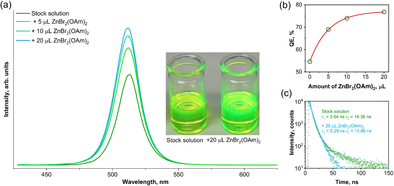 | ||
| Fig. 3 Evolution of emission spectra (λex = 365 nm) intensity (a) and QEs (b) of CsPbBr3 QDs in toluene as a function of the added amount of ZnBr2 complex; PL decay curves of stock CsPbBr3 QDs solution and solution treated with 20 μL of ZnBr2 complex (c). The visual color difference of stock and modified CsPbBr3 QDs solutions at daylight (insert in (a)). | ||
It was observed that the addition of a small amount (5 μL) of ZnBr2-oleylamine complex had a significant impact on both the emission intensity (Fig. 3a) and photoluminescence quantum efficiency (Fig. 3b) of the synthesized CsPbBr3 QDs. The integrated emission intensity increases by 1.4, 1.5, and 1.6 times after adding 5, 10, and 20 μL of ZnBr2-oleylamine complex solution, respectively. Furthermore, the QE increased from 54.7% for the CsPbBr3 QDs stock solution to 76.9% for the solution treated with 20 μL ZnBr2-oleylamine complex. Besides, the changes in the appearance of CsPbBr3 QDs in toluene before and after Zn-complex treatment could even be observed by the naked eye (see the insert in Fig. 3a). It is important to note that the position of the CsPbBr3 QDs emission maximum does not change during the surface treatment with ZnBr2-oleylamine complexes. On the other hand, the emission intensity increased considerably. This increase in emission intensity and PL QE is probably caused by the removal of the surface defects.31 To support such a hypothesis, the PL decay curves for stock and modified (with 20 μL of ZnBr2-oleylamine) CsPbBr3 QDs solutions in toluene were recorded and plotted in Fig. 3c. The biexponential decay function fitted both PL decay curves. The quantitative comparison of the stock and modified CsPbBr3 QDs solution PL decay values and their weight factors is given in Table 1.
| CsPbBr3 | τ1, ns | A1, % | τ2, ns | A2, % | τ, ns |
|---|---|---|---|---|---|
| Stock solution | 3.64 | 74.5 | 14.36 | 25.5 | 6.38 |
| Modified solution | 5.29 | 85.1 | 13.66 | 14.9 | 6.06 |
A relatively large proportion (25.5%) of the long lifetime component (τ2) appeared in a stock CsPbBr3 QDs solution, which is consistent with the delayed photoluminescence typically caused by surface electron traps. After the treatment using ZnBr2-oleylamine solutions, the proportion of the long lifetime component (τ2) of CsPbBr3 reduced to 14.9%, indicating that a part of the surface defects was removed.
Additionally, the short-term (5 days) optical stability experiment was performed with the aim of clarifying the QE evolution of perovskite QDs stock solution and modified CsPbBr3 QDs as a function of time. The freshly prepared samples of CsPbBr3 QDs were modified with ZnBr2(OAm)2 using the same above-described procedure. Both, stock and modified QDs were stored in closed vessels at ambient temperature. The QEs for both samples were calculated directly after the preparation and as a function of time up to five days (in one day intervals). Besides, the performed stability test of the stock and modified QDs also proved that the proposed synthesis method is highly reproducible since the obtained QE values were virtually identical as in the previous synthesis, i.e., 54.7% (initial synthesis) and 55.3% (repeated synthesis) for stock QDs, and 76.9% (initial synthesis) and 76.7% (repeated synthesis) for modified QDs. It was observed that the QE of perovskite stock CsPbBr3 QDs solution dropped to 54.1% and 46.7% after one and five days, respectively. In contrast, the QE of modified CsPbBr3 QDs solution exhibited outstanding optical stability and decreased from 76.7% to only 75.1% in five days. Furthermore, no visible precipitates we observed in both stock or modified QDs solutions (at least within five days of the experiment).
During the post-synthesis treatment of CsPbBr3 QDs with ZnCl2-oleylamine or ZnI2-oleylamine complex solutions, it was observed that the emission of the perovskite QDs solutions is dependent on the amount of added complex. Additionally, the color change of the CsPbBr3 QDs solutions during the post-synthesis treatment with the respective complexes was almost instantaneous (please refer to Videos S1 and S2 provided in ESI).† In order to evaluate the real-time ion exchange dynamics, the change in emission spectra as a function of time after ZnCl2(OAm)2 or ZnI2(OAm)2 complex solutions were added to the CsPbBr3 QDs stock solutions, was measured. The obtained results are summarized in Fig. 4. The initial observation was that the ion exchange process is highly dependent on the amount of added zinc halogenide complex. It turned out that the ion exchange process was slower if a smaller amount of zinc halogenide complex was added. For example, if 50 μL of ZnCl2(OAm)2 solution was added to the CsPbBr3 QDs stock solution, the emission maximum shifted from 513 to 496 nm in 5.0 to 7.5 seconds (please refer to Fig. 4a and b). The emission shift is accompanied by a slight emission intensity decrease which can be evaluated in Fig. 4b. The increase of added ZnCl2(OAm)2 solution to 500 μL, on the other hand, yielded substantially different results. In this case, the emission maximum shifts from 513 to 439 nm within 2.5 to 3.0 s (please refer to Fig. 4c and d). Obviously, the ion exchange rate is much faster if a higher amount of ZnCl2(OAm)2 complex solution is used, i.e., the ion exchange rate increases ca. 2.5-fold when ZnCl2(OAm)2 complex amount is increased 10-fold. Besides, the first fully modified QDs (weak emission at ca. 439 nm) were observed after 0.5 s of adding 500 μL ZnCl2(OAm)2 complex solution followed by a sharp intensity decrease of emission at 513 nm. After 0.5 to 2.0 s, the emission spectra show the multimodal distribution of the QDs, indicating that the fully modified, partially modified, and unmodified CsPbBr3 QDs exist at the same time.
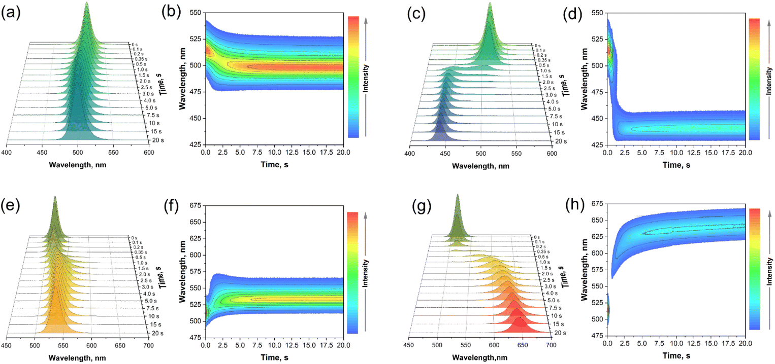 | ||
| Fig. 4 Evolution of emission spectra as a function of time and the contour plot of CsPbBr3 QDs during post-synthesis treatment with 50 μL ZnCl2(OAm)2 (a, b); 500 μL ZnCl2(OAm)2 (c, d); 50 μL ZnI2(OAm)2 (e, f) and 500 μL ZnI2(OAm)2 (g, h) complex solutions. | ||
The post-synthesis treatment of CsPbBr3 QDs stock solution with 50 μL ZnI2(OAm)2 complex solution (please refer to Fig. 4e and f) yielded similar results as in the case of treatment with 50 μL ZnCl2(OAm)2 complex solution. The emission intensity initially decreased and then, after 1 s, started increasing again, followed by the emission maximum shift to longer wavelengths. It took about 7.5 s for the initial emission maximum at 513 nm to shift and stabilize at 532 nm. However, the addition of 500 μL ZnI2(OAm)2 complex solution to the CsPbBr3 QDs stock solution (please refer to Fig. 4g and h) gave the most interesting results. After the addition of 500 μL ZnI2(OAm)2 complex solution, the 513 nm emission started decreasing substantially and almost vanished after 0.35 s (please refer to Fig. 4g). The most fascinating part of this is that the weak emission at ca. 570 nm also starts appearing only 0.30–0.35 s after the start of the experiment. This shows that after the addition of a large amount of ZnI2(OAm)2 complex solution, the CsPbBr3 QDs start instantly losing bromine ions from the surface; therefore, the emission is quenched almost to zero. However, the iodide ions do not incorporate into the QDs yet, since the emission maximum does not change, as shown in Fig. 4g. Later, the emission at 570 nm gains more intensity and shifts to longer wavelengths (644 nm (after 20 s)). We need to emphasize that the emission maximum completely stabilized (at 658 nm) only after 3 minutes from the start of the experiment. The acquired data show that after the addition of a high amount of ZnCl2(OAm)2 or ZnI2(OAm)2, complex solution the CsPbBr3 QDs instantly start losing bromide ions from the surface. It is also clear that chloride ions incorporate into the QDs sites more rapidly if compared to the iodide ions. Once the surface bromide ions are replaced by iodide ions, a further exchange of ions from the deeper parts of QDs takes place, evidenced by the shift of emission maximum. However, not all bromide ions are replaced by iodide ions even after a long period of time since the emission maximum does not reach 680 nm, as in the case of pure CsPbI3 QDs. The visual experiment of the ion exchange procedure and the optical properties of the modified QDs, recorded on the more accurate spectrometer FLS980 (Edinburgh Instruments, Livingston, UK), are presented in Fig. 5. Fig. 5a shows the color of CsPbBr3 QDs stock solutions compared to the one boosted by adding 20 μL ZnBr2-oleylamine. Is it evident that boosted sample appears much brighter in daylight. Subsequently, 50, 100, 200, and 500 μL of ZnCl2-oleylamine or ZnI2-oleylamine complexes were added to the CsPbBr3 QDs stock solutions, and instant color changes were observed, as shown in Fig. 5b. With the increasing amount of added ZnCl2-oleylamine complex, the color of the QDs solution changed from vibrant yellow-greenish to cyan, blue, and, finally, colorless. On the other hand, the increased amount of added ZnI2-oleylamine complex changed the color of the QDs solution from vibrant yellow-greenish to yellow, orange, and, finally, deep red. The emission of QDs modified by ZnCl2-oleylamine or ZnI2-oleylamine complexes under UV radiation is shown in Fig. 5c. It is obvious that virtually any color can be obtained from a single CsPbBr3 QDs solution by simply adjusting the amount of ZnCl2-oleylamine or ZnI2-oleylamine complex. The visual experiment of multicolor emission QDs preparation is provided in Video S3.†
 | ||
| Fig. 5 The color gamut of CsPbBr3 QDs solutions before (a) and after the ion exchange procedure using appropriate amounts of ZnCl2(OAm)2 or ZnI2(OAm)2 complexes in daylight (b) and under UV excitation (c); evolution of PL emission spectra (λex = 365 nm) (d); the position of color coordinates, presented in CIE 1931 color space diagram (e) and PL emission maximum values (f) of the synthesized CsPbBr3 QDs as a function of the added amount of ZnCl2 or ZnI2 complex; PL emission maximum values; comparison of QEs of all-inorganic perovskite QDs, emitting at a different wavelength, which is obtained via individual synthesis (black) and via ion exchange (red), respectively (g). | ||
The recorded emission spectra of CsPbBr3 QDs and their ZnCl2-oleylamine or ZnI2-oleylamine complex modified counterparts are presented in Fig. 5d. It is evident that CsPbBr3 QDs treatment using ZnCl2-oleylamine and ZnI2-oleylamine solutions resulted in a blue and red shift of emission, respectively. It is also clear that any emission wavelength in the visible could be obtained, which is in line with the results discussed in Fig. 5c. Moreover, we have observed that the FWHM of emission spectra decreases if emission spectra shift towards the blue spectral region. For instance, the emission maximum of CsPbBr3 QDs stock solution shifted from 513 to 439 nm after the modification with 500 μL ZnCl2-oleylamine solution. At the same time, the FWHM decreased from 21.5 nm (0.104 eV) to 15.4 nm (0.098 eV). The opposite tendency, however, was observed if emission shifted towards the red spectral region, i.e., the emission maximum of CsPbBr3 QDs stock solution shifted from 513 to 658 nm after the modification with 500 μL ZnI2-oleylamine solution and FWHM increased from 21.5 nm (0.104 eV) to 37.9 nm (0.112 eV). The calculated FWHW values for different emission spectra of perovskite QDs are in good agreement with the data published in the literature,11 where the authors claim that FHWM values of all-inorganic perovskites regarding to their emission color could vary in the range of 12–42 nm.
The absorption spectra as a function of added amounts of ZnCl2-oleylamine and ZnI2-oleylamine complexes are given in Fig. S2.† The absorbance of CsPbBr3 QDs shifts to longer wavelengths with the increasing amount of added ZnI2-oleylamine complex, whereas adding ZnCl2-oleylamine complex causes the blue shift of absorption spectra. These results are in line with the ones reported for the separate synthesis of CsPbX3 (X = Cl, Br, I) QDs.35 The color coordinates (in CIE 1931 color space) of the obtained QDs were calculated from their respective emission spectra and are plotted in Fig. 5e. All calculated color coordinates, especially in the blue and yellowish-green to red regions, are located close to or directly on the edge of the CIE 1931 color space diagram. It means that surface modification of CsPbBr3 QDs yielded all-inorganic perovskite QDs with high color purity.
Fig. 5f shows the change of CsPbBr3 QDs emission maximum as a function of added ZnX2-oleylamine complexes amount during the modification. It also demonstrates that at high ZnX2-oleylamine complex concentration, the saturation is reached, and further increase of zinc halide complexes amount has a negligible effect in the change of emission color. To the best of our knowledge, the ion exchange is surface dependent, and the ZnX2-oleylamine complexes could not penetrate deep into bulk QDs; otherwise, the perovskite crystal structure would be destroyed. Besides, there is one more piece of evidence that ZnX2-oleylamine complexes do not penetrate deep into the QDs. For instance, Fig. 5g demonstrates that the peak emission of separately prepared CsPbCl3 is around 400 nm. However, when CsPbBr3 QDs are modified with the ZnCl2-oleylamine complex, the shortest obtained peak emission value is around 439 nm. This value cannot be further decreased since the saturation is reached (the increased amount of added ZnCl2-oleylamine complex does not change the emission), indicating that bromide ions are still present within the perovskite structure. The same applies if CsPbBr3 QDs are modified with the ZnI2-oleylamine complex.
The XRD patterns of CsPbBr3 before and after modification with different amounts of ZnCl2(OAm)2 and ZnI2(OAm)2 complex solutions are shown in Fig. S3.† The XRD peaks shift to higher 2θ angles with increasing the added ZnCl2(OAm)2 amount. This indicates that Cl− successfully incorporate into perovskite structure, thus shrinking the unit cell. The opposite shift of XRD peaks was observed with increasing amount of added ZnI2(OAm)2 complex. This also prove that I− incorporate into the perovskite structure and expands the unit cell. Furthermore, it is also clear that after adding high amount of ZnI2(OAm)2 complex, a majority of Br− are replaced by I−, the compound becomes unstable in air and completely decomposes yielding the amorphous phase as shown in Fig. S3.† This observation is in agreement with previously published data.37
During this study, the question arose which synthesis method is better. The synthesis of individual all-inorganic perovskite QDs using different lead halogenide (PbCl2, PbBr2, PbI2, or their mixtures) salts as precursors or the surface modification of CsPbBr3 QDs using the post-synthesis treatment? To answer the question, a series of separate cesium lead perovskite QDs with different compositions were synthesized by the ultrasound-induced hot-injection method. The comparison of QE for QDs obtained by individual synthesis and by surface modification is presented in Fig. 5g. The individual synthesis method enabled obtaining QDs covering the wider region of visible spectra, i.e., from ca. 405 to 680 nm, if compared to those obtained via surface modification (emits from 439 to 658 nm). However, the perovskites obtained by surface modification/treatment exhibited up to 10–15% higher QEs in such a desirable red region if compared to those obtained by separate synthesis. To conclude, both approaches have their advantages; however, the post-synthesis modification, where the desired emission color could be simply and instantly adjusted by using ZnX2-oleylamine (X = Cl, I) complexes, seems to be more reasonable. Moreover, using ZnX2-oleylamine complexes for surface treatment provides better optical stability of all-inorganic lead perovskites due to surface passivation.
Conclusions
Within this extensive study, the ultrasound-induced hot-injection synthesis method for the preparation of well-defined CsPbBr3 QDs was proposed. This method is very simple and highly reproducible. Moreover, the synthesis of QDs can be performed in merely 15–20 minutes. It was also observed that employment of even a low amount of ZnBr2-oleylamine complex significantly impacts the CsPbBr3 QDs emission intensity and, at the same time, the quantum efficiency. The quantum efficiencies of CsPbBr3 QDs were boosted from 54.7% to 76.9% after adding as little as 20 μL of ZnBr2-oleylamine complex due to partially removed surface defects. This indeed was confirmed by the PL decay curves where the weight coefficient of the long lifetime (τ2) component decreased with increasing the amount of added ZnBr2-oleylamine complex. The surface treatment of CsPbBr3 QDs employing ZnX2-oleylamine (X = Cl, I) complexes resulted in almost instantaneous emission color change that could cover virtually the full range of the visible spectrum. It was also observed that the rate of the ion exchange process could be controlled by adjusting the amount of zinc halogenide complex added, with higher amounts leading to a faster process. Moreover, it is worth noting that while the ion exchange process may be fast, the full-color stabilization of the modified CsPbBr3 ODs still occurs within a period of 3 minutes. The color coordinates of the modified QDs, calculated from their emission spectra, show high color purity, especially in the blue and yellowish-green to red regions. The saturation of the emission color is reached at high concentrations of ZnX2-oleylamine (X = Cl, I) complexes, suggesting that the ion exchange is surface-dependent and the complexes do not penetrate deep into the bulk of the QDs. The stability of the modified QDs is also improved by the addition of these complexes. Moreover, the QEs of QDs emitting in the red spectral region were enhanced by up to 10–15% after the QDs surface treatment. The presented method for changing the color of all-inorganic perovskite QDs to produce nanomaterials with multicolor emission is simpler than previous methods reported in the literature. This method does not require any additional purification steps. In addition, the use of zinc-halogenide complexes has been shown to not only result in the desired color change of the QDs but also to lead to the improved long-term stability of the particles due to the passivated surface.Author contributions
Conceptualization, A. K. and V. K.; methodology, V. K.; investigation, E. E. and V. K.; resources, A. K. and S. S.; writing—original draft preparation, E. E. and V. K.; writing—review and editing, A. K. and V. K.; visualization, M. M., E. E. and V. K.; supervision, A. K. and V. K.; project administration, A. K.; funding acquisition, A. K. All authors have read and agreed to the published version of the manuscript.Conflicts of interest
There are no conflicts to declare.Acknowledgements
The authors acknowledge financial support from the European Regional Development Fund (project No 01.2.2-LMT-K-718-03-0048) under a grant agreement with the Research Council of Lithuania (LMTLT).References
- T. Q. Ma, S. W. Wang, Y. W. Zhang, K. X. Zhang and L. X. Yi, J. Mater. Sci., 2020, 55, 464–479 CrossRef CAS
.
- B. Jeong, H. Han, Y. J. Choi, S. H. Cho, E. H. Kim, S. W. Lee, J. S. Kim, C. Park, D. Kim and C. Park, Adv. Funct. Mater., 2018, 28, 1706401 CrossRef
- K. Chen, X. H. Deng, G. Dodekatos and H. Tuysuz, J. Am. Chem. Soc., 2017, 139, 12267–12273 CrossRef CAS PubMed
- H. Wang and D. H. Kim, Chem. Soc. Rev., 2017, 46, 5204–5236 RSC
- F. P. G. de Arquer, A. Armin, P. Meredith and E. H. Sargent, Nat. Rev. Mater., 2017, 2, 16100 CrossRef
- J. P. Deng, J. L. Li, Z. Yang and M. Q. Wang, J. Mater. Chem. C, 2019, 7, 12415–12440 RSC
- Z. P. Hu, Z. Z. Liu, Z. J. Zhan, T. C. Shi, J. Du, X. S. Tang and Y. X. Leng, Adv. Photonics, 2021, 3, 034002 CAS
- W. J. Chen, X. Q. Li, Y. W. Li and Y. F. Li, Energy Environ. Sci., 2020, 13, 1971–1996 RSC
- M. B. Faheem, B. Khan, C. Feng, M. U. Farooq, F. Raziq, Y. Q. Xiao and Y. B. Li, ACS Energy Lett., 2020, 5, 290–320 CrossRef CAS
- W. G. Chi and S. K. Banerjee, Angew. Chem., Int. Ed., 2022, 61, e202112412 CAS
- L. Protesescu, S. Yakunin, M. I. Bodnarchuk, F. Krieg, R. Caputo, C. H. Hendon, R. X. Yang, A. Walsh and M. V. Kovalenko, Nano Lett., 2015, 15, 3692–3696 CrossRef CAS PubMed
- Y. W. Pan, Y. F. Zhang, W. M. Kang, N. P. Deng, Z. R. Yan, W. Sun, X. Y. Kang and J. Ni, Adv. Mater., 2022, 3, 4053–4068 RSC
- Q. Pan, H. C. Hu, Y. T. Zou, M. Chen, L. Z. Wu, D. Yang, X. L. Yuan, J. Fan, B. Q. Sun and Q. Zhang, J. Mater. Chem. C, 2017, 5, 10947–10954 RSC
- H. W. Liu, Z. N. Wu, H. Gao, J. R. Shao, H. Y. Zou, D. Yao, Y. Liu, H. Zhang and B. Yang, ACS Appl. Mater. Interfaces, 2017, 9, 42919–42927 CrossRef CAS
- M. Chen, Y. T. Zou, L. Z. Wu, Q. Pan, D. Yang, H. C. Hu, Y. S. Tan, Q. X. Zhong, Y. Xu, H. Y. Liu, B. Q. Sun and Q. Zhang, Adv. Funct. Mater., 2017, 27, 1701121 CrossRef
- D. M. Jang, D. H. Kim, K. Park, J. Park, J. W. Lee and J. K. Song, J. Mater. Chem. C, 2016, 4, 10625–10629 RSC
- Y. Tong, E. Bladt, M. F. Ayguler, A. Manzi, K. Z. Milowska, V. A. Hintermayr, P. Docampo, S. Bals, A. S. Urban, L. Polavarapu and J. Feldmann, Angew. Chem., Int. Ed., 2016, 55, 13887–13892 CrossRef CAS PubMed
- A. Kostopoulou, D. Vernardou, K. Savva and E. Stratakis, Nanoscale, 2019, 11, 882–889 RSC
- S. Seth and A. Samanta, Sci. Rep., 2016, 6, 37693 CrossRef CAS PubMed
- H. Z. Yang, Y. H. Zhang, J. Pan, J. Yin, O. M. Bakr and O. F. Mohammed, Chem. Mater., 2017, 29, 8978–8982 CrossRef CAS
- X. M. Li, Y. Wu, S. L. Zhang, B. Cai, Y. Gu, J. Z. Song and H. B. Zeng, Adv. Funct. Mater., 2016, 26, 2435–2445 CrossRef CAS
- T. J. Milstein, K. T. Kluherz, D. M. Kroupa, C. S. Erickson, J. J. De Yoreo and D. R. Gamelin, Nano Lett., 2019, 19, 1931–1937 CrossRef CAS PubMed
- Q. A. Akkerman, V. D'Innocenzo, S. Accornero, A. Scarpellini, A. Petrozza, M. Prato and L. Manna, J. Am. Chem. Soc., 2015, 137, 10276–10281 CrossRef CAS PubMed
- P. Z. Liu, W. Chen, W. G. Wang, B. Xu, D. Wu, J. J. Hao, W. Y. Cao, F. Fang, Y. Li, Y. Y. Zeng, R. K. Pan, S. M. Chen, W. Q. Cao, X. W. Sun and K. Wane, Chem. Mater., 2017, 29, 5168–5173 CrossRef CAS
- V. G. V. Dutt, S. Akhil and N. Mishra, ChemNanoMat, 2020, 6, 1730–1742 CrossRef CAS
- F. Di Stasio, S. Christodoulou, N. J. Huo and G. Konstantatos, Chem. Mater., 2017, 29, 7663–7667 CrossRef
- J. Y. Woo, Y. Kim, J. Bae, T. G. Kim, J. W. Kim, D. C. Lee and S. Jeong, Chem. Mater., 2017, 29, 7088–7092 CrossRef CAS
- L. J. Ruan, B. Tang and Y. Ma, J. Phys. Chem. C, 2019, 123, 11959–11967 CrossRef CAS
- J. N. Yang, Y. Song, J. S. Yao, K. H. Wang, J. J. Wang, B. S. Zhu, M. M. Yao, S. U. Rahman, Y. F. Lan, F. J. Fan and H. B. Yao, J. Am. Chem. Soc., 2020, 142, 2956–2967 CrossRef CAS PubMed
- J. Pan, S. P. Sarmah, B. Murali, I. Dursun, W. Peng, M. R. Parida, J. Liu, L. Sinatra, N. Alyami, C. Zhao, E. Alarousu, T. K. Ng, B. S. Ooi, O. M. Bakr and O. F. Mohammed, J. Phys. Chem. Lett., 2015, 6, 5027–5033 CrossRef CAS PubMed
- F. Li, Y. Liu, H. L. Wang, Q. Zhan, Q. L. Liu and Z. G. Xia, Chem. Mater., 2018, 30, 8546–8554 CrossRef CAS
- L. Z. Wu, Q. X. Zhong, D. Yang, M. Chen, H. C. Hu, Q. Pan, H. Y. Liu, M. H. Cao, Y. Xu, B. Q. Sun and Q. Zhang, Langmuir, 2017, 33, 12689–12696 CrossRef CAS PubMed
- B. A. Koscher, J. K. Swabeck, N. D. Bronstein and A. P. Alivisatos, J. Am. Chem. Soc., 2017, 139, 6566–6569 CrossRef CAS PubMed
- D. Sato, Y. Iso and T. Isobe, ACS Omega, 2020, 5, 1178–1187 CrossRef CAS PubMed
- A. Katelnikovas, M. Steponaviciute, E. Ezerskyte, A. Drabavicius and V. Klimkevicius, Mater. Today Chem., 2022, 26, 101163 CrossRef CAS
- S. Toso, D. Baranov, C. Giannini, S. Marras and L. Manna, ACS Mater. Lett., 2019, 1, 272–276 CrossRef CAS PubMed
- R. Grisorio, M. E. Di Clemente, E. Fanizza, I. Allegretta, D. Altamura, M. Striccoli, R. Terzano, C. Giannini, M. Irima-Vladu and G. P. Suranna, Nanoscale, 2019, 11, 986–999 RSC
Footnote |
| † Electronic supplementary information (ESI) available: Video S1: blue emission shift of CsPbBr3 QDs during titration using ZnCl2-oleylamine solutions; Video S2: red emission shift of CsPbBr3 QDs during titration using ZnI2-oleylamine solutions; Video S3: experiment multicolor emission via surface treatment of CsPbBr3 QDs. Fig. S1: XRD patterns of stock CsPbBr3 QDs and QDs modified with different amounts of ZnBr2(OAm)2 complex solutions. Fig. S2: absorption spectra of stock CsPbBr3 and modified perovskites QDs employing the different amounts of ZnX2(OAm)2 complex solutions (X = Cl, I). Fig. S3: XRD patterns of stock CsPbBr3 QDs and QDs modified with different amounts of ZnX2(OAm)2 complex solutions (X = Cl, I). See DOI: https://doi.org/10.1039/d3ra02143b |
| This journal is © The Royal Society of Chemistry 2023 |