
 Open Access Article
 This Open Access Article is licensed under a Creative Commons Attribution-Non Commercial 3.0 Unported Licence
Improvement of photocatalytic activity in the degradation of 4-chlorophenol and phenol in aqueous medium using tin-modified TiO2 photocatalysts†
I. Rangel-Vázquez *a,
G. Del Angelb,
E. Ramos-Ramíreza,
F. Gonzálezc,
Próspero Acevedo-Peñad,
C. Martínez Gómeza,
F. Tzompantzib,
Norma Gutiérrez-Ortegae and
J. G. Torres-Torresf
*a,
G. Del Angelb,
E. Ramos-Ramíreza,
F. Gonzálezc,
Próspero Acevedo-Peñad,
C. Martínez Gómeza,
F. Tzompantzib,
Norma Gutiérrez-Ortegae and
J. G. Torres-Torresf
aDepartamento de Química, División de Ciencias Naturales y Exactas, Campus Guanajuato de la Universidad de Guanajuato, Noria Alta s/n, Col. Noria Alta, Gto, Guanajuato, C. P. 36050, Mexico. E-mail: efren35200390@gmail.com
bDepartamento de Química, Av. Ferrocarril San Rafael Atlixco, Núm. 186, Col. Leyes de Reforma 1 A Sección, Alcaldía Iztapalapa, C.P. 09310, Ciudad de México, México
cDepartamento de Ingenieria de Procesos e Hidráulica, Universidad Autónoma Metropolitana-Iztapalapa, Av. Ferrocarril San Rafael Atlixco, Núm. 186, Col. Leyes de Reforma 1 A Sección, Alcaldía Iztapalapa, C.P. 09310, Ciudad de México, México
dCONACYT-Laboratorio Nacional de Conversión y Almacenamiento de Energía CICATA-Legaria, Instituto Politecnico Nacional, Calzada Legaria 694. Col. Irrigación, C. P. 11500, Ciudad de México, Mexico
eDivisión de Ingenierias, Departamento de Ingeniería Civil y Ambiental, Universidad de Guanajuato, Gto, Guanajuato, 36000, Mexico
fUniversidad Juárez Autónoma de Tabasco, Laboratorio de Nanomateriales Catalíticos Aplicados al Desarrollo de Fuentes de Energía y de Remediación Ambiental, Centro de Investigación de Ciencia y Tecnología Aplicada de Tabasco (CICTAT), DACB, Km. 1 Carretera Cunduacán-Jalpa de Méndez AP. 24, Cunduacán, C. P. 86690, Tabasco, Mexico
First published on 11th May 2023
Abstract
In this work, we present the synthesis of TiO2 photocatalysts modified with different % mol of tin using the sol–gel method. The materials were characterized using different analytical techniques. The Rietveld refinement, XPS, Raman and UV-Vis techniques confirm the substitution of tin in the TiO2 structural lattice due to changes in crystal lattice parameters, the low-energy shift of the Sn 3d5/2 orbital, generation of oxygen vacancies and the decreased band gap and increased BET surface area. The material with 1 mol% tin shows superior catalytic activity compared to the references for the degradation of 40 ppm 4-chlorophenol (3 hours of reaction) and 50 ppm phenol (6 hours of reaction). Reactions fit pseudo first order kinetics in both instances. The increase in photodegradation efficiency was attributed to the generation of energy levels below the TiO2 conduction band caused by the incorporation of 1% mol of tin, oxygen vacancies, and the heterojunction formed between the brookite–anatase–rutile, causing inhibition of the recombination of the electron (e−) and hole (h+) photogenerated species. The easy synthesis, low cost and increased photodegradation efficiency of the photocatalyst with 1 mol% tin have the potential to favor the remediation of recalcitrant compounds in water.
Introduction
Globally, humanity currently faces difficult challenges within the ecological environment due to the increase in the human population and the increase in industrialization, which have repercussions and various consequences for living beings.1,2 Some effects that stand out are the deterioration of the ozone layer, severe droughts, pollution of rivers and lakes, and the scarcity of drinking water, which is the product of demographic overexploitation and excessive use by different industries, such as the use of phenolic compounds for the manufacture of cosmetics and pharmaceutical products, paints, the textile industry, etc.1,3 Additionally, the water used by these industries is discharged as effluent into different water currents. This is a dangerous practice that brings serious environmental contamination and severe damage to human health that ranges from simple headaches, to mutations, cancer, and even death from over exposure to them.Currently, the scientific community has turned its attention to develop highly efficient alternatives for the elimination of phenolic compounds due to the suspicion that the compounds are endocrine disruptors (EDCs) and constitute a particular priority group of the EPA.4 There are several primary processes such as chemical, physical and biological. However, these methods are inefficient as the compounds are complex, chemically stable, resistant and cannot be removed entirely.5 An alternative is the implementation of heterogeneous photocatalysis, since it is a process considered as a solution to the environmental problem; for being friendly to the environment and for its high efficiency in the elimination of recalcitrant compounds1,3,6–8 and for obtaining clean and renewable energy through the photocatalytic water splitting process9,10 so as not to depend on fossil fuels.
TiO2 is the most used and promising semiconductor for photocatalytic applications due to its characteristics such as non-toxicity, low-cost, resistance and chemical stability. Likewise, when it is irradiated with UV irradiation, electron and hole charge carriers are photogenerated in the semiconductor, which later migrate to the surface of the semiconductor where the oxidation and reduction processes take place causing the photodegradation of recalcitrant compounds.11,12 However, TiO2 has the disadvantage of rapid recombination of charge carriers, lack of efficiency under sunlight, and bandwidth gap (Eg) only activated under UV irradiation.
Recently there has been a great interest in implementing new strategies to improve photoresponse using different light sources (UV or UV-Vis). One way to delay the recombination process of charge carriers for their application to degrade recalcitrant pollutants and in the generation of renewable energy sources is through various alternatives such as; doping with metals such as Sn, Fe, Zr, Mn, W and Mo,13–17 non-metals such as S, Br, N, P, g-C3N4, etc.,3,12,18,19 coupling with another semiconductor, semiconductor/non-metal or non-metal/non-metal with different morphology favoring type II heterojunctions,7–10 generation of ternary hybrid materials between semiconductors and non-semiconductors10,20,21 or simply by impregnating noble metal nanoparticles.22
In the literature, it has been observed that the recombination of charge carriers is inhibited by incorporating tin into TiO2, due to the increase in redox potential and improved catalytic activity.16,23–25 This effect is attributed to the incorporation of tin into the TiO2 lattice due to the similar ionic radius of Sn4+ (0.609 Å) and Ti4+ (0.605 Å). Another factor, such as the synthesis method, can directly influence the structural properties and crystallinity, and enhance the photoactivity of tin-modified TiO2 photocatalysts. There are different synthesis methods and precursors for obtaining tin-modified TiO2 photocatalysts: solvothermal, combustion, coprecipitation, etc.;25–28 however, the methods mentioned are expensive. In contrast, the sol–gel method is a simple, easy and cheap process. For this reason, in this manuscript, we report the synthesis of tin-doped TiO2 nanoparticles using the sol–gel method in order to study the influence of tin in the TiO2 structure. For the modification of the photocatalysts, different mol percentages of tin were used for doped-TiO2, and the TiO2 and SnO2 reference samples were synthesized, to characterize them by different techniques later. The catalytic activity of tin-doped photocatalysts was studied through the degradation of 40 ppm 4-chlorophenol and 50 ppm phenol in an aqueous medium under UV light irradiation.
Experimental
(a) Synthesis of photocatalysts and references
The reference photocatalysts (TiO2 and SnO2) and doped-TiO2 (with 1, 3 and 5% mol of tin) were synthesized by the sol–gel method, using the following precursors; titanium(IV) isopropoxide (Aldrich), SnCl2·2H2O (Aldrich), isopropanol (Aldrich), HCl (Aldrich) and deionized water. A desired ration of titanium and tin precursors are placed into a flask containing isopropyl alcohol, under a nitrogen atmosphere. Subsequently, the pH of the transparent solution is adjusted to a value of 3 using HNO3, and left to reflux for 24 hours with constant stirring. Finally, water and isopropanol are incorporated into the flask, maintaining a 4![[thin space (1/6-em)]](https://www.rsc.org/images/entities/char_2009.gif) :16 molar ratio (water-isopropanol), and refluxed for another 24 hours. Subsequently, the photocatalysts are filtered and washed with water to remove excess chlorine contained in the tin precursor salt. The photocatalysts are dried in an oven at 120 °C for 12 hours. Henceforth the photocatalysts will be named SnXT, where X corresponds to the molar percentage of tin added during the synthesis (1, 3 and 5%), and the references will be named Sn0T and Sn100T.
:16 molar ratio (water-isopropanol), and refluxed for another 24 hours. Subsequently, the photocatalysts are filtered and washed with water to remove excess chlorine contained in the tin precursor salt. The photocatalysts are dried in an oven at 120 °C for 12 hours. Henceforth the photocatalysts will be named SnXT, where X corresponds to the molar percentage of tin added during the synthesis (1, 3 and 5%), and the references will be named Sn0T and Sn100T.
(b) Characterization of photocatalysts
(c) Photocatalytic tests for 4-chlorophenol and phenol degradation
The catalytic activity is carried out in a Bach-type glass reactor, incorporating 200 ml of solution of the pollutant under study. The pollutant molecules are 40 ppm and 50 ppm of 4-chlorophenol and phenol, respectively. The photocatalytic reaction is carried out with an air flow (60 ml min−1), 1 g L−1 of photocatalyst, at room temperature, and with constant agitation for each of the experiments performed. The irradiation source is a Pen-Ray Hg-lamp (λ = 254 nm and 4000 μW cm−2). Before starting the photocatalytic reaction, the pollutant solution is left with the photocatalyst without turning on the irradiation source for 1 hour to achieve the adsorption–desorption equilibrium of the probe molecule, at the end of the equilibration period, the irradiation source is turned on to start pollutant degradation. The phenol degradation reaction is monitored every hour for 6 hours and for 4-chlorophenol every 15 minutes during 3 hours of reaction, using a 0.45 μm Millipore filter. Aliquots are analyzed using an UV-Vis spectrometer (Agilent Cary 60) following the absorption band at 278 nm for 4-chlorophenol and 270 nm for phenol. The degradation of each probe molecule is also followed by TOC (Total Organic Carbon) in a Shimadzu 50000 TOC equipment.Results and discussion
(a) TGA/DTA
TGA/DTA profiles of Sn0T and Sn1T photocatalysts are shown in Fig. 1a and b, respectively. In Fig. 1a, weight losses are observed in the temperature ranges of 28–200 °C, 200–430 °C and 430–550 °C. The first temperature interval corresponds to an endothermic peak with a weight loss (6.5%) attributed to the evaporation of the residual solvent and the removal of water.13,31 In the second interval, the weight loss (4.8%) corresponds to an exothermic peak and is associated with the combustion of organic matter, elimination of structural hydroxyl groups and the transition from the amorphous phase to the crystalline anatase phase.31,32 In the third interval, an exothermic peak centered at 482 °C is located, it is associated with the allotropic transformation of anatase to rutile.33 The Sn1T photocatalyst (see Fig. 1b) has the following range of 28–200 °C, 200–443 °C and 443–521 °C. The first interval is associated with an endothermic peak due to the loss of solvent and water with loss of weight (7.5%). The second interval (weight loss (3%)) is correlated to the combustion of organic matter, elimination of structural hydroxyl groups, decomposition of chloride ions and the transition from the amorphous phase to the anatase phase of TiO2.16 The last interval of 443–521 °C is associated with the crystalline phase transition from anatase to rutile and the incorporation of tin into the TiO2 matrix is observed to reduce the crystallization temperature of anatase to rutile compared to TiO2 and a peak is observed at 767 °C, associated with the complete transformation of the nanocrystals from anatase to rutile.34 According to the analysis obtained, the calcination temperature was determined for all materials at 400 °C for 4 hours.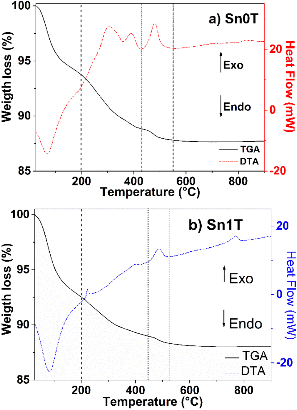 | ||
| Fig. 1 TGA/DTA analysis of photocatalysts (a) Sn0T and (b) Sn1T. | ||
(b) X-ray diffraction
Fig. 2 shows the diffraction patterns of the Sn0T, Sn100T and SnXT photocatalysts where X = 1, 3 and 5% mol of tin. For the Sn0T photocatalyst, the crystallographic planes (101), (103), (004), (112), (200), (105) (211), (213), (204) and (116) are shown, corresponding to the Bragg reflections at 2θ = 25.28°, 36.94°, 37.80°, 38.57°, 48.05°, 53.89°, 55.06°, 62.12°, 62.69° and 68.76° which are associated with the tetragonal structure of the anatase phase of TiO2 (JCPDS 12-1272 Quality: Star (*), item (b) in Fig. 2).34,35 However, at a temperature of 400 °C, the Sn0T photocatalyst presents a small peak located at 27.53° as a function of angle 2θ, which corresponds to the (110) plane of the tetragonal structure of the TiO2 rutile phase (JCPDS 21-1276 Quality: Star (*), item (c) (*) within Fig. 2), this same effect of obtaining rutile at low temperature (350 °C) has been previously reported in the literature.13 For the Sn100T photocatalyst, the crystallographic planes (110), (101), (200), (111), (210), (211), (220), (002), (310), (112) and (301) are shown, that correspond to the peaks with reflection as a function of 2θ = 26.59°, 33.88°, 37.95°, 38.99°, 42.64°, 51.78°, 54.76°, 57.85°, 61.89°, 64.76° and 65.98° which are associated with the tetragonal structure of SnO2 (cassiterite JCPDS 04-003-0649 Quality: Star (*), item (d) inside Fig. 2).36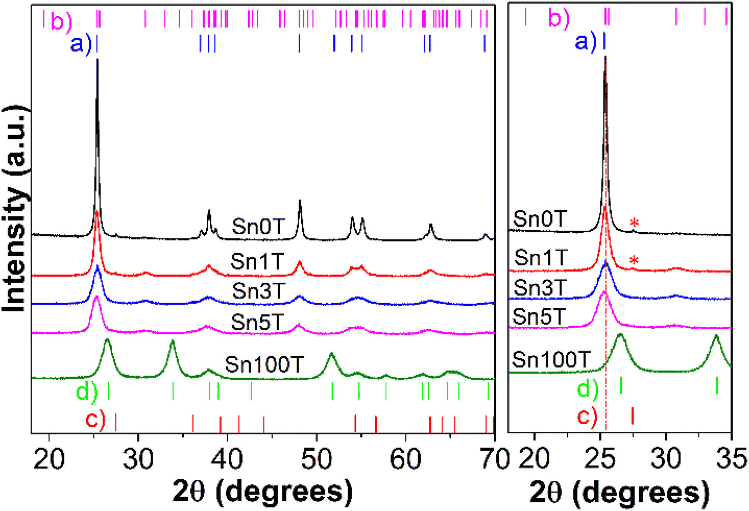 | ||
| Fig. 2 X-ray diffraction patterns of synthesized photocatalysts calculated by Rietveld refinement subsequently. | ||
For the other photocatalysts (see Fig. 2 left) SnXT, where X is 1, 3 and 5% mol tin, the reflections are observed as a function of 2θ that correspond to the anatase phase (JCPDS 12-1272 Quality: Star (*)) and to the brookite phase (JCPDS 29-1360 Quality: Star (*) item (b) Fig. 2) of TiO2 and the other characteristic reflections of SnO2 are not observed. This indicates that tin oxide is not segregated on the surface and that consequently it is incorporated into the TiO2 structure. However, only the reflection at 2θ = 27.53° of the plane (110) corresponding to the rutile phase of TiO2 for the Sn1T photocatalyst is presented, this association can be made as a result of the synthesis method, calcination temperature, and the fact that several authors report that tin promotes crystallization from anatase to rutile at low temperature.24,37
In order to determine if tin is incorporated into the TiO2 crystalline structure, it is necessary to use Rietveld refinement. The cell parameters, crystal size and the composition of the different phases (% weight) are obtained by Rietveld analysis and are shown in Table 1. The incorporation of tin into TiO2 results in the coexistence of the three polymorphs in the Sn1T photocatalyst, having a relative concentration (% weight) of approximately 75.9% (anatase), 22.0% (brookite) and 2.1% (rutile). For the Sn3T and Sn5T photocatalysts, only 65.4% and 66.8% by weight of anatase and 34.6% and 33.2% of brookite are observed, and the rutile phase is not found. It should be noted that the tin-content-dependant incorporation causes a decrease in the intensity of the anatase signal, which causes a decrease in crystal size of 41–60% for the photocatalysts Sn1T, Sn3T and Sn5T with respect to Sn0T and the cell parameters obtained from the refinement of the anatase, brookite and rutile structures were observed to be modified; distorting the lattice parameters due to the increase in the concentration and substitution of tin to the TiO2 structural lattice. This fact is consistent with the incorporation of tin probably as Sn4+ to the TiO2 structural lattice due to the total oxidation process in airflow and the change of species Sn2+ to Sn4+.16,38
| Sample | Anatase | Brookite | Rutile | ||||||||||
|---|---|---|---|---|---|---|---|---|---|---|---|---|---|
| Cell parameters (nm) | Crystal size (nm) | Rel. conc. (%) | Cell parameters (nm) | Crystal size (nm) | Rel. conc. (%) | Cell parameters (nm) | Crystal size (nm) | Rel. conc. (%) | |||||
| a | c | a | b | c | a | b | |||||||
| a The parenthesis () in the text an Table 1, represents the standard deviation and corresponds to the variation in the last digit of the values of the parameters a, b and c of the cell parameters. Rel. conc. = relative concentration of each of the phases observed in TiO2 by Rietveld refinement.b SnT100 corresponds to the SnO2 cassiterite crystalline phase which is isostructural with the TiO2-rutile phase. The cell parameters of SnO2 are larger than those corresponding to the TiO2-rutile phase, since the ionic radius (VI coordination) of Sn4+ (69.0 pm) is larger than that of Ti4+ (60.5 pm). | |||||||||||||
| Sn0T | 0.37850(12) | 0.95020(35) | 28.1(2) | 98.2(3) | — | — | — | — | — | 0.45930(10) | 0.25590(5) | 25.2(4) | 1.8(3) |
| Sn1T | 0.37893(2) | 0.95036(6) | 18.3(2) | 75.9(5) | 0.9187(4) | 0.5441(3) | 0.5183(2) | 9.2(2) | 22.0(4) | 0.46010(16) | 0.29759(19) | 24.1(2) | 2.1(1) |
| Sn3T | 0.37929(4) | 0.95128(14) | 12.4(2) | 65.4(4) | 0.9252(6) | 0.5445(4) | 0.5183(2) | 6.0(1) | 34.6(4) | — | — | — | — |
| Sn5T | 0.37958(4) | 0.95414(13) | 11.7(2) | 66.8(7) | 0.9278(8) | 0.5436(5) | 0.5198(3) | 5.0(1) | 33.2(7) | — | — | — | — |
| Sn100Tb | — | — | — | — | — | — | — | — | — | 0.47461(7) | 0.31909(6) | 8(1) | 100 |
According to what has been reported in the literature, in the anatase structure (TiO2) Ti4+ has VI coordination, for this ion to be replaced in the structure the tin ion must have the same size or the ionic radius must be 15% smaller; in this case, the ionic radius of Sn4+ and Ti4+ is 0.690 A and 0.605 Å, respectively with a VI coordination.39,40 On the other hand, the tin ion seems to have lower solubility in the brookite crystalline structure due to an increase in cell parameter a in the Sn1T and Sn3T photocatalysts and no change in the uncertainty of the Rietveld analysis is observed in lattice parameter a with increasing concentration for the Sn5T photocatalyst. For the Sn1T photocatalyst, the rutile lattice parameters are seen to be modified by the incorporation of 1% mol of tin, this is consistent with what has been reported in the literature since tin oxide crystallizes in a rutile-type structure.33 Consequently, the Rietveld analysis of Sn100T was carried out, the lattice parameters obtained from the crystal lattice constants of the cassiterite phase were: a = 0.47461(7) and c = 0.31909(6) Å and the crystal size was 8(1) nm.
(c) XPS
X-ray photoelectron spectroscopy (XPS) is used to determine and identify the chemical states of the elements found in Sn0T, Sn1T, Sn5T and Sn100T photocatalysts. Fig. 3a–c show the high-resolution XPS spectra of Ti 2p, Sn 3d and O 1s for the above mentioned photocatalysts. Fig. 3a shows the results of the deconvolution analysis of the Ti 2p core level spectrum for the Sn0T, Sn1T and Sn5T photocatalysts, in which two defined peaks are observed that correspond to titanium with different oxidation states; Ti3+ and Ti4+. The deconvolution of the high-resolution Ti 2p spectra of the photocatalysts (Sn0T, Sn1T and Sn5T) shows that the highest abundance corresponds to Ti4+, which can be associated with the present crystalline phases detected by anatase X-ray diffraction, brookite and rutile, and Ti3+ is observed in a smaller proportion. The species of Ti3+ is the product of the reduction of Ti4+ due to the chemical reactivity of titanium oxide when synthesizing the photocatalysts by the incorporation of a dopant, high vacuum conditions or ionic erosion.41 In the Sn0T photocatalyst, binding energies (BE) of the core level of Ti 2p3/2 are observed at 458.70 eV, for TiO2 (Ti4+) at 458.85 eV and for Ti2O3 (Ti3+) at 457.24 eV (Table 2). In the literature, several authors report BE very close to the values obtained in our deconvolution, for this reason in the present work the C 1s peak is calibrated at 285.00 eV.13,25,42,43 Another factor that the previously mentioned authors do not consider in deconvolution is that there are different proportions of crystalline phases with the same oxidation state (Ti4+), and this causes the distance of the central peaks of the Ti 2p core level doublet and the resolution of the peak to change (FWHM). Therefore, we associate that the modification of the BE distance between Ti 2p3/2 and Ti 2p1/2 is due to the following: (1) there is not a single crystalline phase with Ti4+ in TiO2, (2) there are symmetry and resolution effects due to the energy step (CAE) in spectrum acquisition and (3) the presence of vacancies. The present data is based on the BE obtained experimentally and corrected with the values of the core level Ti 2p according to our calibration and resolution of the spectrum. The separation of the Ti 2p doublet core level must be fixed for any oxidation state and crystalline phase, in our photocatalysts containing titanium the ΔE = 5.75 eV according to our reference Sn0T (anatase and rutile). Table 2 shows the BE of the deconvolution analysis of the Ti 2p3/2 core level of the photocatalysts. The BE centered at 458.70 eV (82.4%) and 458.85 eV (1.8%) are associated with the anatase and rutile phases in TiO2 (Ti4+) and the BE at 457.24 eV (15.8%) is attributed to Ti3+ in the Sn0T photocatalyst. On the other hand, in the Sn1T and Sn5T photocatalysts a new contribution is presented with a BE centered at 458.58 eV, which is attributed to the brookite phase of TiO2 (Ti4+) with different relative abundances (21.2% Sn1T and 30.8% Sn5T) and a BE centered at 456.99 eV is presented due to the contribution of Ti3+ (10.6% Sn1T and 13.5% Sn5T). The displacement of the Ti3+ BE in the Sn1T and Sn5T photocatalysts compared to the Sn0T reference can be associated with the oxygen vacancies generated and the possible incorporation of tin in the Ti2O3 structure.44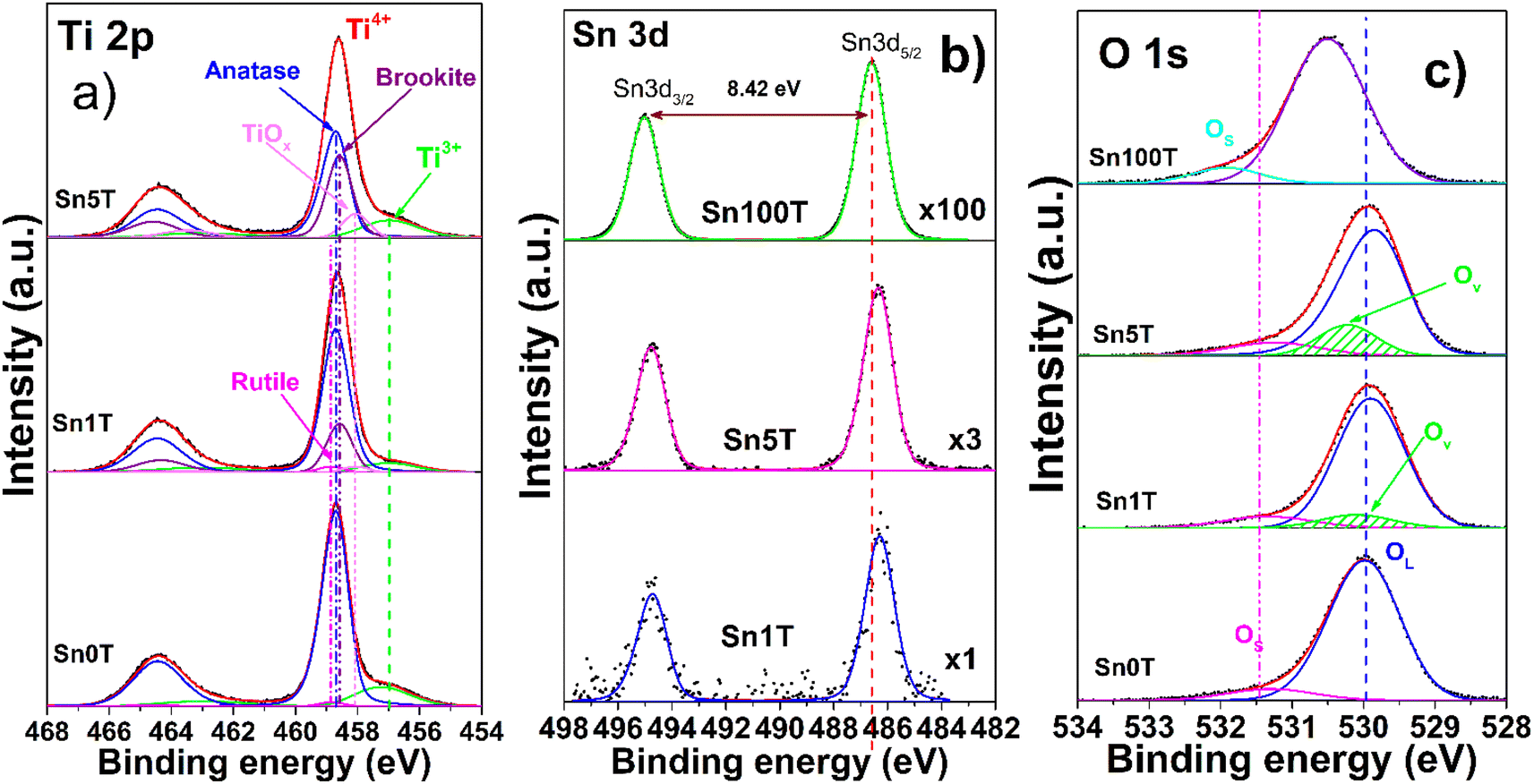 | ||
| Fig. 3 High resolution spectra of the elements Ti 2p (a), Sn 3d (b), O 1s (c) of the SnXT photocatalysts, where X = 0, 1, 5 and 100 mol% of tin. | ||
| Sample | TiO2 | Ti2O3 | TiOx | Oxygen | Tin | ||||
|---|---|---|---|---|---|---|---|---|---|
| Ti 2p3/2 | O 1s | Sn 3d5/2 | |||||||
| Anatase | Rutile | Brookite | Ti3+ | OL | Ov | Os | Sn4+ | ||
| Ti4+ | |||||||||
| (eV) | |||||||||
| Sn0T | 458.7 | 458.85 | — | 457.24 | — | 529.98 | — | 531.30 | — |
| 82.3 | 1.9 | — | 15.8 | — | 91.3 | — | 8.7 | — | |
| Sn1T | 458.7 | 458.85 | 458.58 | 456.99 | 458.06 | 529.9 | 530.1 | 531.34 | 486.30 |
| 62.2 | 2.4 | 21.5 | 10.0 | 3.9 | 81.6 | 8.8 | 9.6 | 100 | |
| Sn5T | 458.7 | — | 458.58 | 456.99 | 458.06 | 529.85 | 530.22 | 531.25 | 486.28 |
| 45.8 | — | 33.1 | 13.5 | 7.6 | 74.8 | 15.1 | 10 | 100 | |
| Sn100T | — | — | — | — | — | 530.5 | — | 531.92 | 486.6 |
| — | — | — | — | — | 91.5 | — | 8.5 | 100 | |
Fig. 3b shows the core level of the high-resolution spectrum of Sn 3d for the photocatalysts Sn100T, Sn1T and Sn5T. For the photocatalyst reference, Sn100T (SnO2), the core level shows a doublet Sn 3d5/2 and Sn 3d3/2 with BE = 486.60 eV and 495.02 eV that corresponds to SnO2 in an oxidation state Sn4+ and no other contribution associated with metallic tin was observed (Sn0 metallic tin) or (Sn2+).23,44,45 The ΔE for the core level for doublet Sn 3d5/2 and Sn 3d3/2 is 8.42 eV (see Fig. 3b). For the photocatalysts with different tin content, the core level of Sn 3d5/2 has a BE = 486.30 eV (Sn1T) and 486.28 eV (Sn5T). Tin incorporation in the Sn1T and Sn5T samples (Table 2) has a shift at low energy (0.30 eV and 0.32 eV) compared to the Sn100T reference, indicating that Sn4+ is incorporated into the TiO2 structure.13,24,32,46
The high-resolution spectra of O 1s (Fig. 3c) of the Sn0T and Sn100T photocatalysts show two contributions (see Table 2), the first is bound to oxygen from the structural lattice for each photocatalyst at 529.98 and 530.50 eV and the second is attributed to surface hydroxyl groups located at 531.30 and 531.92 eV, respectively.45,46 In the high-resolution O 1s spectra, three contributions located at 529.90, 531.34 and 530.10 eV (Sn1T) and at 529.85, 531.25 and 530.22 eV (Sn5T) were observed. These BE are associated with oxygen in the structural lattice hydroxyl groups on the surface and the vacancies generated by the incorporation of tin and interface formed between the phases present in each of the photocatalysts (anatase, brookite and rutile). Oxygen vacancies have been reported to function as an electron trap, thus delaying charge carrier recombination and enhancing photoactivity in the degradation of recalcitrant compounds.44,47
(d) Raman
Raman spectroscopy is used to evaluate the incorporation of tin into TiO2, crystallinity of the phases present, and structural defects in the different synthesized photocatalysts. Fig. 4 shows the main peaks associated with the fundamental modes of vibration of TiO2 (Sn0T) in anatase phase (A) located at 145 cm−1 (Eg), 197 cm−1 (Eg), 398 cm−1 (B1g), 519 cm−1 (A1g) and 641 cm−1 (Eg).45,48 The fundamental modes of vibration of TiO2 in rutile phase are located at 145 cm−1 (B1g), 445 cm−1 (Eg), 610 cm−1; so they are not observed in Sn0T,49 this can be attributed to the small relative proportion found, based on the Rietveld refinement and that this is totally dispersed in Sn0T. For SnXT modified photocatalysts; where X = 1, 3 and 5% mol of tin (see Fig. 4), the vibration modes mentioned above corresponding to the anatase phase (A) are observed and the vibration modes located at 245 cm−1 (A1g) are present at 322 cm−1 (B1g) and 364 (B2g) cm−1; which are associated with the brookite phase (B*) of TiO2.50 For the Sn1T photocatalyst, the vibration modes corresponding to rutile were not observed; this due to the small proportion and that the majority dominant phases are anatase and brookite, which are detected by means of XRD-Rietveld refinement. The results obtained from the SnXT photocatalysts (X = 1, 3 and 5 mol of tin) show the coexistence of crystalline phases (anatase and brookite) of TiO2 and are consistent with the results obtained by XRD-Rietveld and XPS. For the reference Sn100T (not shown), its vibration modes are located at 490 cm−1, 574 cm−1, 636 cm−1 and 776 cm−1.51 In modified materials with different tin content (Sn1T, Sn3T and Sn5T) the vibration modes corresponding to SnO2 are absent, therefore; the incorporation of Sn4+ into the TiO2 structural lattice is indicated and it is corroborated by XRD-Rietveld refinement and XPS. Also, another effect that is observed when incorporating tin (see Fig. 4 inset) is that the mode located at 145 cm−1 suffers a shift towards the blue and a broadening, this is attributed to the confinement of the phonon or non-stoichiometry. This is associated with reticular defects in the structural lattice due to the generation of oxygen vacancies caused by the incorporation of tin (doping).52,53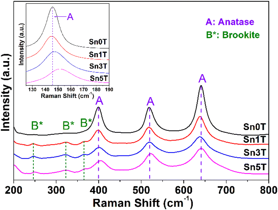 | ||
| Fig. 4 Raman spectra of SnXT photocatalysts: Sn0T, Sn1T, Sn3T, Sn5T. | ||
(e) SEM-EDS
Fig. 5 shows the SEM micrographs and EDS spectra of each one of the elements that constitute the Sn0T and Sn1T photocatalysts. Elemental composition determined by EDS-mapping of each of the samples for each of the elements, O (oxygen), Ti (titanium) and Sn (tin), contained in Sn0T (Fig. 5a) and Sn1T (Fig. 5b) are shown in Fig. 5. On the SEM-mapping images of Sn1T tin was observed to be incorporated into the TiO2 matrix without notorious segregation of SnO2 particles on the TiO2 surface, this fact is verified by XRD-Rietveld refinement and Raman spectroscopy. The elemental composition was studied by EDS in five different zones to obtain a better description for each of the elements, as shown in ESI Fig. 1s.† The composition of each one of them was observed to be variable depending on the area where the EDS spectra were recorded and that the particles do not have uniform morphology and crystal size. The outstanding information of the spectra performed was obtained from the average value with its respective standard deviation for each of the elements of the Sn1T photocatalyst (see ESI Fig. 1s†). The tin element's atomic composition values obtained were close to the value employed during the photocatalysts synthesis.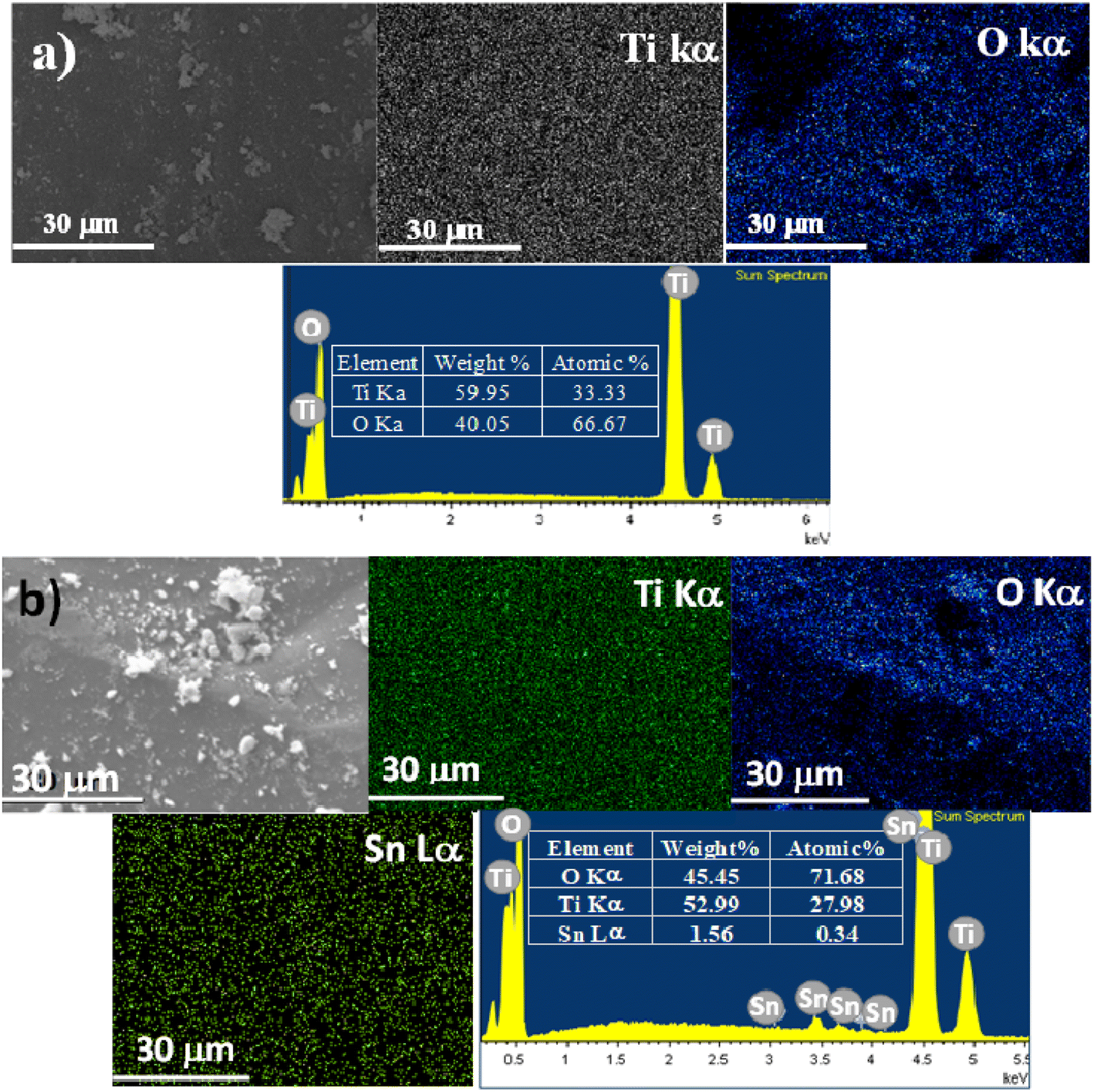 | ||
| Fig. 5 SEM analysis-mapping and elemental composition of the Sn0T (a) and Sn1T (b) photocatalysts. | ||
(f) TEM
The characterization of the photocatalysts to determine the average particle size of Sn0T and Sn1T was performed by TEM. Images of Sn0T and Sn1T are shown in Fig. 6a and b, respectively. The micrographs of the photocatalysts Sn0T and Sn1T confirm these materials have heterogeneous morphologies and crystal size. Sn0T has an average size of 23 nm and when incorporating the tin dopant at 1% mol, the average crystal size is 16 nm (Sn1T). Therefore, the incorporation of tin has the effect of inhibiting particle growth in Sn1T compared to the Sn0T reference, this fact agrees with the results obtained, which the XRD-analysis Rietveld corroborates. Incorporating a dopant into the structural lattice of a metal oxide tends to decrease the crystal size compared to the reference material; this effect has been reported in various photocatalysts for environmental applications.54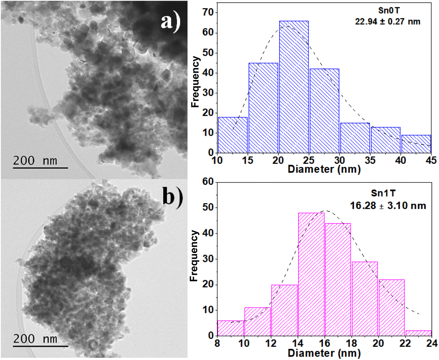 | ||
| Fig. 6 TEM image analysis and average crystal size distribution of Sn0T (a) and Sn1T (b) photocatalysts. | ||
(g) HRTEM
Fig. 7 shows HRTEM micrograph of the Sn1T photocatalyst with its respective analyzed areas (Fig. 7a–d). On the right side of Fig. 7, the different regions analyzed using the FFT-HRTEM of the Sn1T photocatalyst are observed. The planes (105), (200) and (101) are identified from FFT-HRTEM, which are associated with the interplanar distances 1.71 Å, 1.90 Å and 3.53 Å that correspond to the anatase phase (JCPDS PDF 21-1272 Quality Star (*)). The crystallographic planes (032), (111) and (120) correspond to the interplanar distances 1.97 Å, 3.49 Å and 3.51 Å, which are attributed to the brookite phase (JCPDS PDF 29-1360 Quality Star (*)). TiO2 crystallographic planes corresponding to rutile are absent, this is due to dispersion and low relative concentration according to XRD-Rietveld refinement analysis. The different zones were studied (FFT-HRTEM) consecutively and it is not possible to detect the crystallographic planes corresponding to the cassiterite phase (SnO2).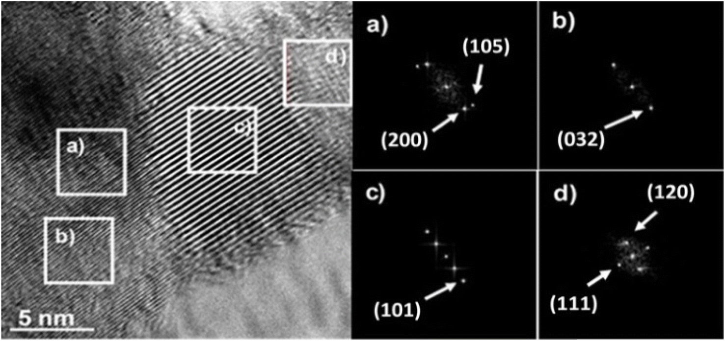 | ||
| Fig. 7 HRTEM image and their respective FFT-HRTEM images of the different areas analyzed (a–d) of the Sn1T photocatalyst. | ||
The evidence described above suggests that the dopant (tin) is incorporated into the TiO2 structural lattice for the photocatalyst (Sn1T), XRD-Rietveld, XPS and Raman corroborate this. Additionally, the coexistence of crystalline phases (anatase and brookite) in Sn1T (see Fig. 7 (left)) reveal the formation of a heterojunction between them, this phenomenon has been reported for a mixture of anatase and rutile.52
(h) UV-Vis spectroscopy (diffuse reflectance)
The optical absorption of the synthesized photocatalysts can be seen in Fig. 8. Determining the band gap value of the different photocatalysts is crucial and is regarded as an essential factor influencing the catalytic activity. Band gap spectra are transformed using the Kubelka–Munk (K–M) method. To determine and know the band gap of the photocatalysts, it is necessary to build the Tauc's graph [(K–M × hν)n vs. energy (hν)]. In the literature an indirect transition has been reported for the TiO2 semiconductor, where the value of n = 1/2.13,46,52 The calculation of the band gap of the SnXT photocatalysts (X = 1, 3 and 5 mol%) is determined by fitting the linear part of the spectrum in the Tauc's graph with the intersection with the abscissa axis (hν) (see graphic inserted in Fig. 8). The calculated band gap value of the different photocatalysts can be seen in Table 3, the value for the Sn0T reference is 3.15 eV (anatase and rutile). Some researchers consider the possible transition of the TiO2 band gap calculation differently: for example, Fresno et al.55 consider direct and indirect transitions obtaining Eg values of 2.94 eV and 3.19 eV, respectively. Marzec et al.36 report a value of 3.18 eV for an indirect transition and Majrik et al.56 mention that the Eg is in the range of 3.0–3.1 eV and other authors generally report the Eg at 3.2 eV for (anatase) TiO2. Therefore, the obtained value of Eg calculated in this work for the Sn0T photocatalyst (anatase and rutile) is within the range previously reported by the authors cited above. For the reference Sn100T (SnO2) the Eg value is 3.6 eV, which coincides with what has already been reported.51,56 On the other hand, incorporation of tin (1, 3 and 5 mol%) into TiO2 decreases the band gap to an interval between 2.90 and 2.97 eV (see Table 3), displacing the absorption edge towards visible spectrum. This modification of the band gap is attributed: (1) to the transition of charge transfer of the electrons of Sn4+ to the conduction band of TiO2,57 (2) to the incorporation of tin into the TiO2 structural lattice, and (3) to the interaction in the mixture of phases (anatase, brookite and rutile) that must form states that function as shallow traps created by oxygen vacancies causing the band gap to decrease.49,52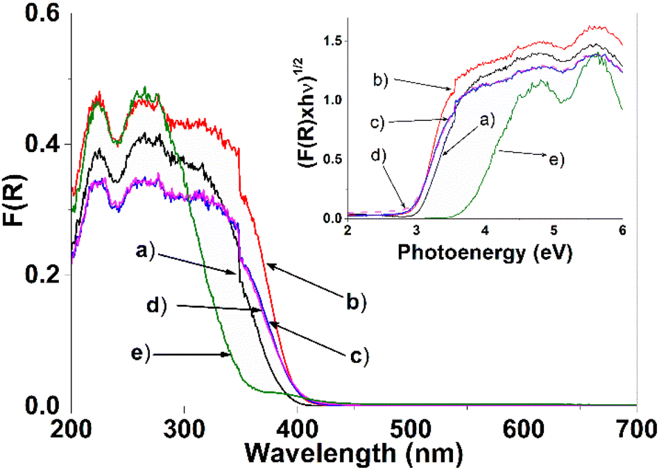 | ||
| Fig. 8 Diffuse reflectance spectra (UV-Vis) and (inset) Tauc plot of the different photocatalysts, (a) Sn0T, (b) Sn1T, (c) Sn3T, (d) Sn5T and (e) Sn100T. | ||
| Sample | Surface specific (BET, m2 g−1) | Pore size (nm) | Pore distribution (cm3 g−1) | Band gap (Eg, eV) | aTOC (%) | bKapp × 10−3 (min−1) | ct1/2 (min) | dC (%) | eTOC (%) | fKapp × 10−3 (min−1) | ct1/2 (min) | gC (%) |
|---|---|---|---|---|---|---|---|---|---|---|---|---|
| a TOC = total organic carbon of 4-chlorophenol at 180 minutes.b Kapp = apparent speed constant calculated at 180 min.c t1/2 = average life time.d C= conversion (%) to 180 minutes.e TOC = total organic carbon of phenol at 360 minutes.f Kapp = apparent speed constant calculated at 360 minutes.g C= conversion (%) at 360 minutes. | ||||||||||||
| Sn0T | 42 | 15.22 | 0.32 | 3.15 | 71.2 | 12.62 | 54.9 | 76.6 | 62 | 5.09 | 136.17 | 76.9 |
| Sn1T | 73 | 5.54 | 0.21 | 2.97 | 91.0 | 25.11 | 27.6 | 95.4 | 87 | 8.84 | 78.41 | 94.0 |
| Sn3T | 94 | 2.81 | 0.14 | 2.93 | 66.4 | 10.95 | 63.3 | 74.7 | 54 | 3.85 | 180.03 | 72.3 |
| Sn5T | 91 | 2.59 | 0.13 | 2.90 | 76.0 | 19.13 | 36.2 | 90.5 | 83 | 8.38 | 82.71 | 90.0 |
| Sn100T | 91 | 15.83 | 0.36 | 3.62 | 20.7 | 2.21 | 313.6 | 12.0 | 15 | 0.35 | — | 13.0 |
(i) BET specific surface area
The textural properties of the photocatalysts Sn0T, Sn100T and SnXT, where X = 1, 3 and 5% mol of tin, and their respective N2 adsorption–desorption isotherms are shown in Table 3 and Fig. 9. The BET area of the Sn0T and Sn100T photocatalysts are 42 m2 g−1 and 91 m2 g−1, respectively. The incorporation of tin into the TiO2 structure modifies the surface area with an increase of 73–94 m2 g−1 (see Table 3). The adsorption–desorption isotherms of the photocatalysts (see Fig. 9) are classified according to IUPAC as type IV,58 which are characteristic of mesoporous materials. Sn0T and Sn100T have the H3 type hysteresis, which is characteristic of pores between plates in the region of the mesopores. The Sn1T photocatalyst has the H1 type of hysteresis, which is typical of ordered pores. Finally, Sn3T and Sn5T photocatalysts have the H2 type of hysteresis, where there are delayed condensation phenomena and pore blocking.59 The pore size of the SnXT photocatalysts is much smaller compared to the references, 15.22 nm (Sn0T) and 15.83 nm (Sn100T) with values of 5.54, 2.81 and 2.59 nm for the contents of 1, 3 and 5% of tin, respectively. Pore volume decreased depending on the tin content of 0.21, 0.14 and 0.13 g cm−3 respectively, this may be due to the distortion of the structural lattice by the incorporation of tin into TiO2.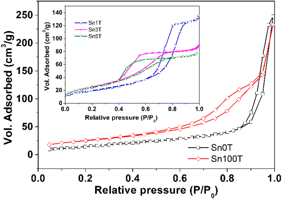 | ||
| Fig. 9 Adsorption isotherms and desorption of N2 photocatalysts SnXT where X = 0, 1, 3, 5 and 100 mol% tin. | ||
(j) Photocatalytic activity
The photocatalytic activity of the materials synthesized and calcined at 400 °C was performed by degradation of 4-chlorophenol (40 ppm, λ = 278) and phenol (50 ppm, λ = 270 nm), in an aqueous medium, using UV light irradiation. The concentration of the molecules was monitored by means of UV-Vis spectrophotometry at different times (each 30 min for 4 chlorophenol and each 60 min for phenol) during the UV irradiation. Degradation of organic compounds does not take place in the absence of a photocatalyst and UV light. The UV-Vis absorbance spectra are shown in Fig. 10 for the photocatalytic degradation for 4-chlorophenol (a) (Sn0T) and (b) (Sn1T), and phenol (c) (Sn0T) and (d) (Sn1T), the total time of reaction was 3 h and 6 h respectively. Before initiating contaminant degradation, the solution of pollutant with the photocatalyst was left in agitation for one hour to allow equilibrium of adsorption–desorption of the contaminant on the catalyst. In the photocatalytic reaction of the 4-chlorophenol at 1 hour of adsorption, without UV light, the materials Sn0T, Sn1T, Sn3T and Sn5T were observe to adsorb approximately between 18 and 22% of the pollutant and that the Sn100T absorbs approximately 20% of the pollutant (see Fig. 11a). If we observe Fig. 10a and b, where the UV absorption spectra for Sn0T and Sn1T photocatalysts is shown, when the solution is irradiated with UV light in both catalysts, absorbance intensity is detected to increase for some time before starting the photodegradation. This behavior, in which the concentration of the pollutant is higher than at the start (after adsorption), is called the photoinduction period, this effect has been reported commonly in hydroxylation reactions in which free radicals have been seen to be involved.22,60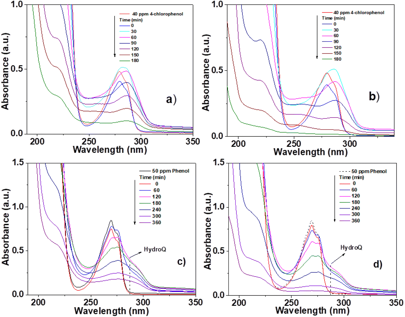 | ||
| Fig. 10 UV-Vis spectra of pollutant degradation using photocatalysts; 4-chlorophenol (a) Sn0T, (b) Sn1T and phenol (c) Sn0T, (d) Sn1T. | ||
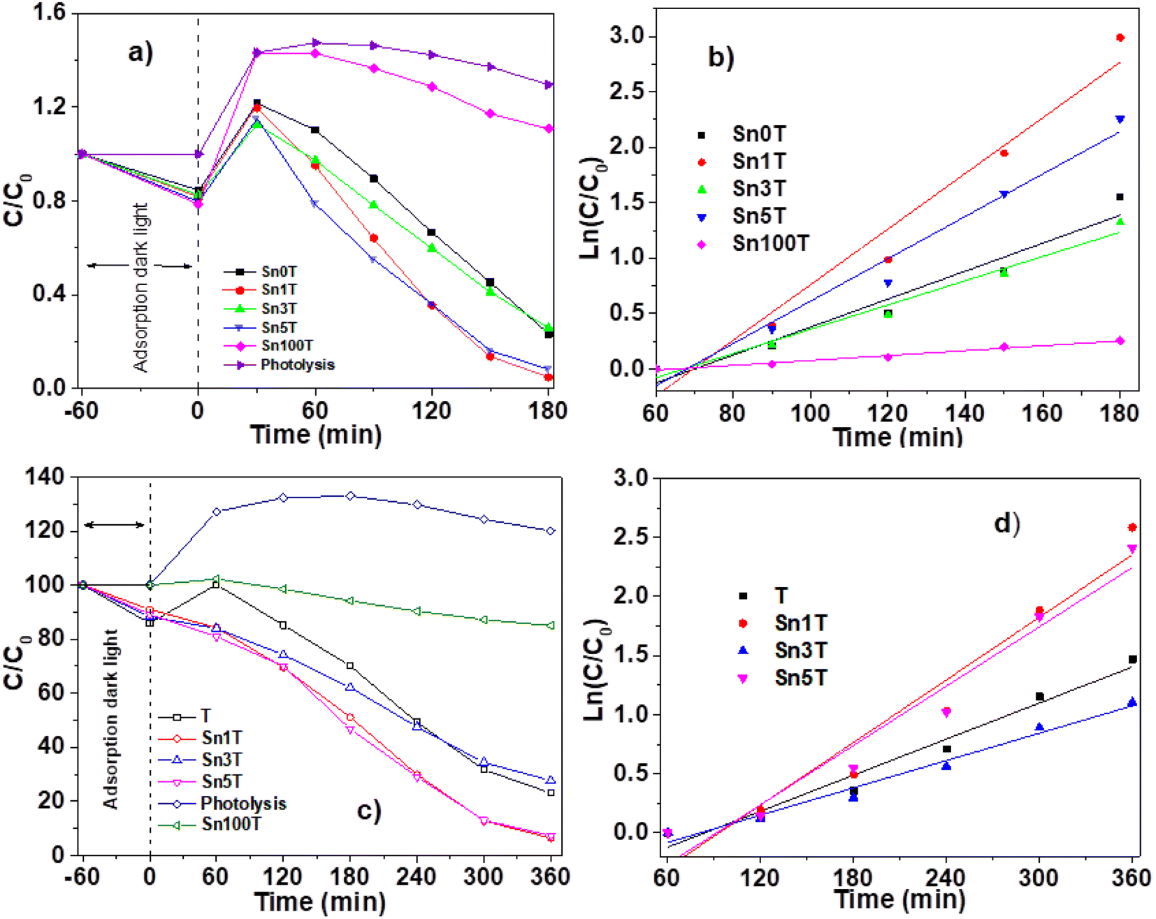 | ||
| Fig. 11 Catalytic activity of SnXT photocatalysts followed by UV-Vis spectroscopy (left) and pseudo first order kinetics (right) for the degradation of 40 ppm 4-chlorophenol (a) and (b) and 50 ppm phenol (c) and (d). | ||
It can also be observed (Fig. 10) that the absorption band after irradiation presents a red-shift forming a new absorption band, this band can be attributed to the formation of an intermediary with a different chromophore, such as hydroquinone (λ = 285 nm) or to the appearance of the ion phenolate (λ = 287 nm).15,61 In the same graph, it was observed that the transitions of the aromatic group π → π* in the range of 190–240 nm for the Sn1T photocatalyst decreases the intensity after 90 min of irradiation compared to the reference Sn0T. The photocatalytic reaction using the Sn0T and Sn1T photocatalysts (Fig. 10a and b) shows a band in the range of 250–310 nm, which decreases considerably with respect to the irradiation time in Sn1T until achieving almost the total degradation of 4-chlorophenol. This band located in the interval mentioned above was associated with the transitions π → π* and the breakdown of the C–Cl link, which is very reactive. In Fig. 11a the degradation of 4-chlorophenol as a function of the temperature for pure and doped catalysts is exposed. The photoinduction effect for all the photocatalysts at 30 minutes of irradiation can be observed. Nevertheless, at 3 h of irradiation (see Fig. 11a) the Sn1T and Sn5T exhibit more activity than the Sn3T and Sn0T photocatalysts. Whereas the pure Sn100T photocatalyst still presented the process of photoinduction.
The mineralization of 4-chlorophenol was also followed by TOC (see Table 4) and was reported for 180 minutes of reaction. The values obtained by TOC analysis for 4-chlorophenol mineralization are shown in Table 4. The most active photocatalyst in the mineralization of 4-chlorophenol was the Sn1T with 91%, a higher value than for reference Sn0T, whose value reached 71% in 3 hours of reaction. Degradation results and kinetic parameters of 4-chlorophenol in SnXT materials can be seen in the Table 4. The degradation of 4-chlorophenol was adjusted to a kinetics of pseudo-first order showing that the Sn1T has the highest Kapp value, of around double that of the Sn0T reference and the highest conversion to 180 minutes with 95.4%. The half-life time of SnXT photocatalysts degradation is lower than the respective references (see Table 4) and Sn1T photocatalyst exhibits the shortest time (27.6 min−1) compared to the Sn3T and Sn5T photocatalysts.
| Photocatalysts | Preparation method | Pollutants | Work conditions |
|---|---|---|---|
| Ti1−xSnxO2 | Hydrothermal | Phenol (10 mg L−1) | (Anatase), UV light, 0.07 g |
| TiSn3 (3% tin)62 | 70 ml solution, degradation 84.5%, 6 h | ||
| Sn modified to TiO2 (0, 5, 10 and 25%)13 | Surfactant-assisted technique | Diclofenac 3.57 mg L−1 | (Anatase/rutile) (0% Sn) 25% diclofenac, 17% acetaminophen and 25% ibuprofen (10% Sn), visible light, 5 mg and 25 ml 3 h |
| Acetaminophen 194.5 mg L−1 | |||
| Ibuprofen 2.82 mg L−1 | |||
| Black SnO2–TiO263 |
Sol–gel | Phenol (10 mg L−1) | (Anatase/rutile) xenon lamp (500 W) 25 mg, 25 ml solution 82.3% 180 minutes |
| Sn:Ti 1:2 |
|||
| SnO2 doped-TiO264 1:9 % mol |
Sol–gel | Phenol (10 mg L−1) | (Anatase/rutile) halogen lamp (400 W) 50 ml solution 50 mg, 90% after 2 h |
| Sn doped-TiO2 (1% mol Sn) in this work | Sol–gel | Phenol (50 mg L−1) | (Brookite/anatase/rutile) UV light, (4.4 mW cm−2) 200 mg, 200 ml solution 94% 6 h |
The UV-Vis spectra for the degradation of 50 ppm of phenol using the Sn0T and Sn1T materials can be seen in Fig. 10c and d and the degradation% as a function of time in Fig. 11c. For the Sn0T and Sn1T photocatalysts, around 15% and 9% of the contaminant was adsorbed, respectively, for 1 hour to reach the adsorption-equilibrium of the pollutant on the surface of the photocatalyst in the absence of UV light. After this time, the UV light was turned on and after 1 hour of irradiation, the Sn0T photocatalyst presented the photoinduction process, like that observed in the 4-chlorophenol degradation and presented a new band which is attributed to the formation of hydroquinone (285 nm) as an intermediary. For the Sn1T photocatalyst, after the adsorption process and 1 hour of irradiation, the photoinduction process does not happen, but the degradation process proceeds slower, diminishing absorbance for 1 h of irradiation and producing hydroquinone (285 nm) as an intermediary (Fig. 10c and d).
The results of the degradation, mineralization and the kinetic parameters of phenol degradation over Sn0T, Sn100T and SnXT photocatalysts are reported in Table 4. After the irradiation of the polluted solution with UV light for 6 hours was finished, the most active photocatalyst was observed to be the Sn1T doped catalyst with a degradation of 94%. The order in activity for the rest of the photocatalysts was: Sn5T > Sn0T > Sn3T > Sn100T with values of 90.0, 76.9, 72.3, 13.0 conversion%, respectively (Fig. 11c and Table 4). Similarly, the mineralization was followed by TOC during 6 hours of reaction, the most active material was Sn1T with 87% of mineralization, the SnXT and pure references of photocatalysts followed the same order that the phenol degradation (Table 4). The experimental data of phenol degradation was adjusted to kinetics of pseudo first order (see Fig. 11d). The kinetic parameters Kapp, t1/2, are reported in Table 4, where the best photocatalyst was observed to be Sn1T.
(k) Fluorescence to determine the hydroxyl radical
The main species in the degradation or decomposition of organic compounds in the photocatalytic process is the hydroxyl radical (˙OH). This species has a high oxidative potential of 2.80 eV (V vs. NHE). Photogenerated hydroxyl radicals during the photocatalytic process in an aqueous medium come from two possible routes: (1) the OH– (hydroxy) attached to the surface of the catalyst and (2) the ˙OH produced by the photogenerated holes (h+) in the valence band of the semiconductor where the water is adsorbed. For this reason, detecting the production of hydroxy radicals in the photocatalytic process in necessary to verify whether the photogenerated hydroxy radicals on the catalyst surface are responsible for the degradation of 4-chlorophenol and phenol. The detection of hydroxyl radicals in the photocatalytic process is complex under irradiation with a UV light source; however, Ishibashi et al.29 proposed a simple method to detect this species. This consists of using terephthalic acid as a probe molecule that functions as a trap of hydroxyl radicals. Terephthalic acid has no fluorescence, but when trapping radicals produces 2-hydroxyterephthalic acid that has fluorescence and an emission length of 425 nm. Fig. 12 shows the fluorescence graphics: (a) without catalyst, (b) pure Sn0T and (c) the most active catalyst Sn1T. The fluorescence intensity is observed to have a maximum at 425 nm corresponding to the formation of 2-hydroxyterephthalic acid. The concentration of 2-hydroxyterephthalic acid is directly proportional to the concentration of the hydroxyl radicals photogenerated in the process of photooxidation; therefore, the kinetics in the process of photodegradation of hydroxyl radicals is of zero order in the time interval under study.62 The detection of radicals in the photocatalysts follows the descending order; Sn1T > Sn0T > photolysis. For the above, the incorporation of tin to the TiO2 structure lattice favors the load separation photogenerated as e− (electron) and h+ (hole) in the photocatalytic process in such a way that it favors the increase of hydroxyl radicals on the surface of the catalyst improving the photocatalytic activity in the degradation of 4-chlorophenol and phenol. The results obtained are shown through the representation commonly used in Fig. 12d, which confirms that Sn0T (TiO2) and Sn1T (TiO2 doped with 1% tin) have a higher production of radicals with respect to the reaction in the absence of photocatalyst (photolysis), and at the same time it is found that Sn1T produces a greater amount of ˙OH radicals and this effect is associated with the material that has the highest photocatalytic activity. The rate of radical production is correlated with the slope and our results show that the slope for photolysis is 3.15, for Sn0T it is 6.39 and for Sn1T it is 13.45. The production of ˙OH radicals in the photocatalyst Sn1T is twice the production of Sn0T and 4 times more than photolysis, this agrees with the results obtained in the catalytic activity in the degradation of 4-chlorophenol (40 ppm) and phenol (50 ppm).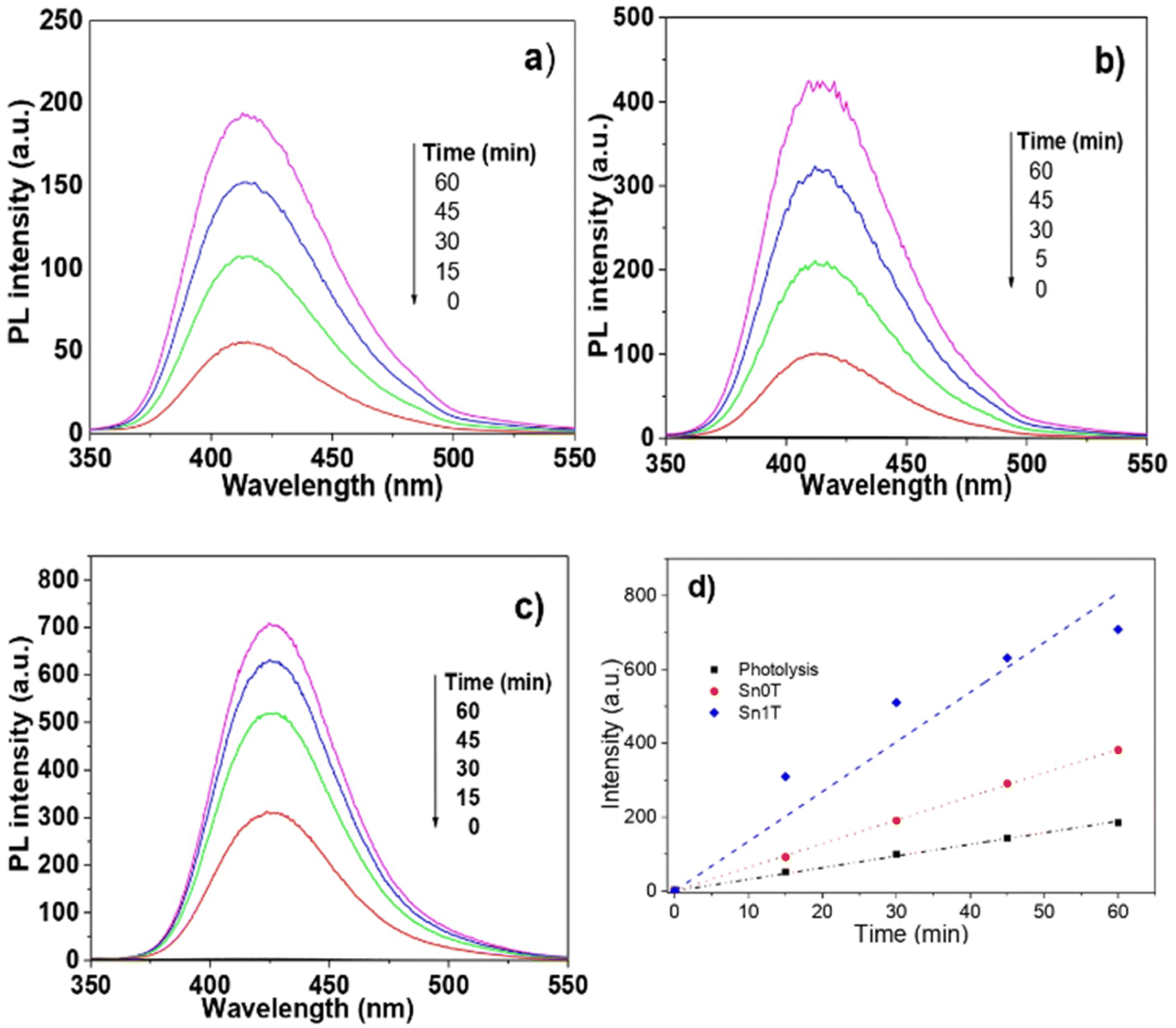 | ||
| Fig. 12 Radical detection (˙OH) by means of fluorescence using terephthalic acid and NaOH, where (a) photolysis, (b) Sn0T, (c) Sn1T and (d) representation of the relative concentration of ˙OH radical production. | ||
(l) (Photo)electrochemical characterization
(Photo)electrochemical characterization of the synthesized photocatalysts is shown in Fig. 13a. The Mott–Schottky plots for all the materials exhibit a positive slope indicating the n-type behavior of the photocatalysts; additionally, tin incorporation into de TiO2 displaces the flat band potential towards more negative values only for Sn1T. This behavior can be related to the combination of doping and the coexistence of three TiO2 polymorphs in the photocatalysts. Energetic states generated at the interfaces junction has been reported to displace the flat band potential towards values more negative than the TiO2 starting material.63 Meanwhile, when doping is performed with higher tin contents (Sn3T and Sn5T) the flat band potentials displace towards less negative values, closer to that measured for the Sn100T. This behavior suggests the generation of energetic states below the conduction band of the TiO2. As discussed previously in the text, tin incorporation into TiO2 lattice generates oxygen vacancies.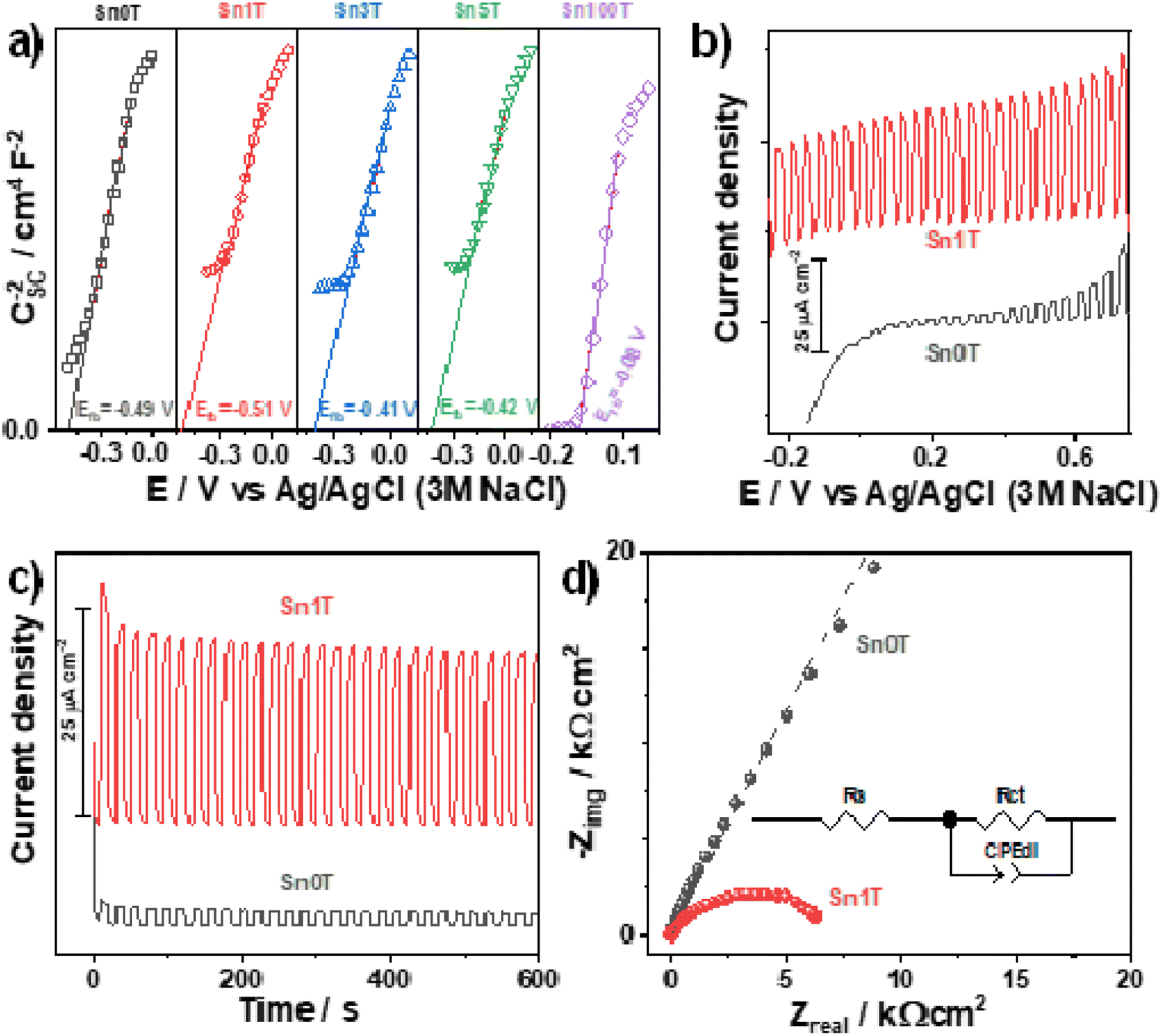 | ||
| Fig. 13 (Photo)electrochemical characterization of the photocatalysts. (a) conduction band edge position determined using Mott–Schottky plots for all the photocatalysts. Photocurrent generation for Sn0T and Sn1T measured by: (b) linear sweep voltammetry (ν = 10 mV s−1) and (c) chronoamperometry at 0.5 V. (d) EIS measured for Sn0T and Sn1T under illumination. | ||
The photocurrent generated during a linear swept voltammogram or at a constant potential is a measurement of the charge-separation process capability of the photocatalysts, particularly, when generated states or heterojunction do not trap the charge-carries. I vs. E and I vs. t plots were measured under chopped illumination for the reference material Sn100T and the oxide with the better photocatalytic behavior (Sn1T), see Fig. 13b and c. Photocurrent measured (Fig. 13b) shows that Sn1T can generate larger photocurrents than Sn0T due to the improved charge separation promoted by the formation of the anatase/brookite/rutile heterojunction and oxygen vacancies generation caused by the tin doping. It is worth mentioning that the measured photocurrent remains high even at lower or negative potentials indicating that electrons are being efficiently transported toward the current collector, leaving the holes at the surface of the photocatalysts to perform water oxidation. Additionally, Sn1T also exhibits a larger photocurrent generation at a constant potential with high stability with time.
Finally, the EIS spectra (Fig. 13d) of the semiconductors were evaluated at open circuit potential under illumination to estimate the charge transfer resistance (diameter of the formed distorted semicircle), which is inversely proportional to the initial photocatalytic rate. The experimental spectra were fitted with the equivalent circuit inserted in Fig. 13d. The continuous lines show the best fitting of the equivalent circuit to the experimental data. Rs stands for the solution resistance, Rct for the charge-transfer resistance, and CPEdl is a constant phase element for the double-layer capacitance. A CPE has been selected instead of a pure capacitor to compensate for the effect of rugosity. Sn1T shows the lowest impedance values indicating an improved charge transfer compared to Sn0T. The improved charge separation and charge transfer in Sn1T together with an efficient generation of oxidant species, are responsible for the enhanced photocatalytic performance of this material. Sn1T shows the lowest impedance values indicating an improved charge transfer compared to Sn0T. The improved charge separation and charge transfer in Sn1T together with an efficient generation of oxidant species, are responsible for the improved photocatalytic performance of this material.
(m) Photoluminescence
It is well known that the photocatalytic activity of semiconductor materials is closely correlated with the recombination of the photoinduced charge carriers, namely electrons and holes. The electron–hole recombination often gives place to photoluminescence and when it is present, the slower the recombination process is, the lower the PL intensity and the higher the photocatalytic activity are. Therefore, the photoluminescent emission spectra are an important tool to investigate the incorporation of impurity species, the migration and transfer of photoinduced charge carriers, and the surface defects, which have an impact on the recombination efficiency. Regarding the anatase based TiO2 photocatalyst, the photoluminescent emission spectra show bands ascribed to self-trapped excitons, surface states associated with defects, and oxygen vacancies,64 all of them being beneficial for the catalytic activity. Thus, in order to further support the best performance of the Sn1T photocatalyst, ESI Fig. 2s† shows the emission spectra, upon excitation at 320 nm, of the photocatalyst Sn0T, Sn1T, Sn3T and Sn5T annealed at 400 °C.Noticeably, the lowest PL intensity, implying a slower recombination rate, is observed in the emission spectrum of the Sn1T photocatalyst agreeing with its best performance among all the photocatalyst compound series. In addition, it is worth mentioning that all the spectra show bands ascribed to nanoparticle size effects49 (448 nm), self-trapped excitons associated with superficial oxygen deficiency65 (467 nm), charge transfer associated with vacancies due to Ti3+ presence (487 nm) (see XPS results), and oxygen vacancies on the TiO2 surface (520 nm). Then, the photoluminescent results explain the enhancement of the photocatalytic activity in the photocatalyst Sn1T as due to the inhibition of the charge carrier recombination and support the presence of Ti3+ and oxygen vacancies.
(n) Degradation mechanism
The results obtained above can help to propose the possible mechanism by which the degradation of 4-chlorophenol and phenol is carried out with the photocatalysts modified with different % mol of tin. In the literature, the proposed mechanism is the effect of the configuration between energy bands of different band gap.40 This could be applicable to our photocatalysts due to the coexistence of the mixed phases and the interfacial contact between them.Sn0T and Sn100T, photocatalysts with different band gaps (3.15 eV and 3.6 eV), have their own electron affinity and configuration positions between bands that are totally different (CB and VB). Particularly in Sn0T, when irradiated with an UV light source, charge carriers are generated, the electron (e−) migrates to CB and the hole (h+) remains in VB.
However, remember that in this photocatalyst there is interfacial contact because there is a mixture of anatase and rutile, CB of anatase is considered to be above (0.2 eV) the CB of rutile, therefore a type II heterojunction. In the process, interfacial electronic transfer from anatase to rutile for the degradation of contaminants, is considerable as there is a small proportion of rutile, according to the DRX-Rietveld analysis, so it is considered that there are energy states that function as electron traps.66 In Sn100T the charge carrier recombination process is very fast, so the catalytic activity is very low compared to Sn0T and Sn1T (see Table 4).
On the other hand, if both photocatalysts are considered to be bound, Sn0T (3.15 eV) and Sn100T (3.6 eV) with respect to the CB of each of them, the CB of Sn100T is below the CB of Sn0T.25,48,63 However, in SnXT photocatalysts it should be considered that the incorporation of tin affects the TiO2 structural network due to the substitution of Sn4+ for Ti4+ in the TiO2 structural network, so that the substitution adds energy states below the CB and they act as an electron trap and have the function of separating the charge carriers and thus increasing the photoactivity in the degradation of 4-chlorophenol and phenol compared to the references.
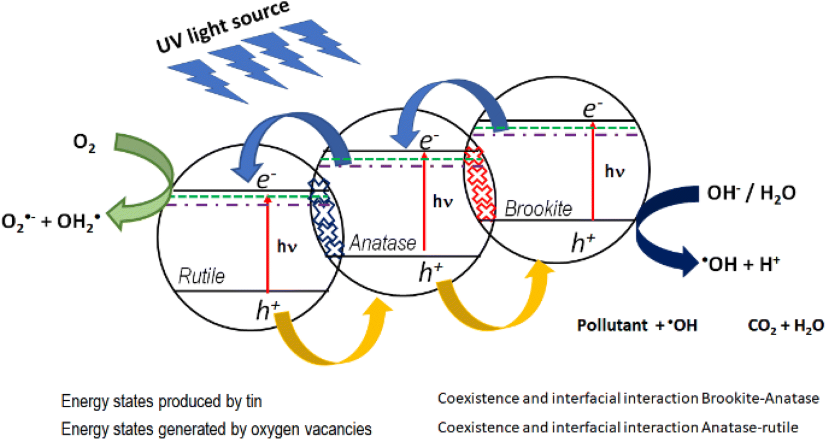
In this work, the most active photocatalyst in the photodegradation of 4-chlorophenol and phenol is Sn1T (2.97 eV). The increase in photoactivity is attributed to the interfacial electron transfer process due to the coexistence of rutile–anatase–brookite, structural defects in the interface and the generation of oxygen vacancies due to the incorporation of tin into the TiO2 structural lattice. Fig. 14 shows the diagram between bands and the interfacial electronic transfer process of the charge carriers in the Sn1T (brookite–anatase–rutile) photocatalyst and that a type II heterojunction between them is generated.
 | ||
| Fig. 14 Possible electronic transfer process for the most active catalyst (Sn1T) in the decomposition of 4-chlorophenol and phenol. | ||
In this sense, the photogenerated electrons in the brookite BC band decay to the states generated by tin and by oxygen vacancies that function as an electron trap and consecutively, due to the interfacial electronic transfer between them, they migrate to the anatase BC. Next, the electrons accumulated in anatase decay to the energy states generated by tin and by oxygen vacancies in anatase and similarly act as an electron trap and by the interfacial transfer between anatase and rutile these decay into the rutile CB. The electrons in the CB of rutile is the place where the reduction reaction takes place and the species O2˙− and OH2˙ are generated. As for the holes, they migrate from the valence band of rutile to anatase and consecutively from anatase to brookite, this process can be carried out due to the coexistence and interfacial interaction between the three TiO2 polymorphs and it is in the VB of brookite where the process of oxidation of the contaminants takes place.
The Sn1T photocatalyst, as mentioned above, presented the highest activity because it has an optimal dopant concentration, this is attributed to structural changes due to the incorporation of tin into the TiO2 structural lattice, interfacial electron transfer, and oxygen vacancies. These factors delay electron–hole recombination, favoring the trapping of charge carriers in the energetic states generated by the addition of tin, and they function as an electron trap, showing superior photocatalytic activity in the degradation of 4-chlorophenol and phenol.
For the incorporation of tin > 1% mol in the SnXT photocatalysts, the degradation of the contaminants can be observed to be greater as compared to the references, this can be attributed to an increase in the surface area, a decrease in crystal size and an increase in oxygen vacancies. However, no trend was found as regards the increase of the properties mentioned above that is a determinant in the degradation of 4-chlorophenol and phenol despite the fact that the process of coexistence and interfacial interaction between brookite–anatase also occurs compared to the more active photocatalyst (Sn1T) (see Table 4).
Conclusions
The Sn0T, Sn100T and SnXT doped with different X mol% tin photocatalysts were prepared by the sol–gel method and tested in the photocatalytic degradation of 4-chlorophenol and phenol. The incorporation of tin to the matrix of pure TiO2 has three effects: (1) the tin ion is incorporated into the TiO2 network, (2) the mixture of anatase, brookite and rutile coexists and (3) the TiO2 particle size decreases at higher tin concentrations. Through XPS the substitution of tin in the TiO2 lattice was corroborated and the binding energies of core level Ti 2p corresponding to the anatase and brookite phase were allocated at 458.70 eV and 458.58 eV. The incorporation of tin at different proportions to TiO2 modifies the surface area and band gap (Eg). The photodegradation of 4-chlorophenol and phenol was more efficient using the concentration of 1% mol, because the ion Sn generates energetic stated, interfacial interaction and oxygen vacancy that function as an electron trap by the coexistence of heterostructure brookite–anatase–rutile, both factors allow the delay of the electron–hole recombination.Author contributions
Israel Rangel-Vázquez: conceptualization, methodology, software, validation, formal analysis, investigation, writing-original draw, writing – review & editing, visualization, project administration, funding acquisition. G. Del Angel: conceptualization, methodology, software, validation, formal analysis, investigation, writing-original draw, writing – review & editing, visualization, project administration, funding acquisition. E. Ramos-Ramírez: conceptualization, methodology, validation, formal analysis, investigation, writing-original draw, writing – review & editing, visualization, project administration, funding acquisition. F. González: methodology, software, validation, formal analysis, investigation, writing-original draw, writing – review & editing, visualization. Próspero Acevedo-Peña: methodology, software, validation, formal analysis, investigation, writing-original draw, writing – review & editing, visualization. C. Martínez Gómez. methodology, formal analysis, investigation, writing-original draw, visualization, funding acquisition. F. Tzompantzi: methodology, formal analysis, investigation, writing-original draw, writing – review & editing, visualization. Norma Gutiérrez-Ortega: methodology, formal analysis, investigation, writing-original draw, writing – review & editing, visualization. J. G. Torres-Torres: methodology, formal analysis, investigation, writing-original draw, writing – review & editing, visualization.Conflicts of interest
There are no conflicts to declare.Acknowledgements
Israel Rangel Vázquez thanks to the Department of Chemistry of the Division of Natural and Exact Sciences of the University of Guanajuato and the Autonomous Metropolitan University-Iztapalapa for all the facilities granted to carry out this work.Notes and references
- R. B. Rajput, S. N. Jamble and R. B. Kale, J. Environ. Manage., 2022, 307, 1–17 CrossRef PubMed.
- F. Dal, E. Mecarelli, R. Aigotti, E. Davoli, P. Calza and C. Medana, J. Environ. Manage., 2022, 308, 114573 CrossRef PubMed.
- R. P. Barkul, R. S. Sutar, M. K. Patil and S. D. Delekar, ChemistrySelect, 2021, 6, 3360–3369 CrossRef CAS.
- U.S. Environmental Protection Agency, 2012 Edition of the Drinking Water Standards and Health Advisories, 2012 Search PubMed.
- C. Descorme, Catal. Today, 2017, 297, 324–334 CrossRef CAS.
- L. N. Costa, F. X. Nobre, A. O. Lobo and J. M. E. de Matos, Environ. Nanotechnol., Monit. Manage., 2021, 16, 100466 CAS.
- W. Shi, K. Shu, H. Sun, H. Ren, M. Li, F. Chen and F. Guo, Sep. Purif. Technol., 2020, 246, 116930 CrossRef CAS.
- Y. Liu, C. Liu, C. Shi, W. Sun, X. Lin, W. Shi and Y. Hong, J. Alloys Compd., 2021, 881, 160437 CrossRef CAS.
- F. Guo, X. Huang, Z. Chen, Y. Shi, H. Sun, X. Cheng, W. Shi and L. Chen, J. Colloid Interface Sci., 2021, 602, 889–897 CrossRef CAS PubMed.
- W. Shi, M. Li, X. Huang, H. Ren, C. Yan and F. Guo, Chem. Eng. J., 2020, 382, 122960 CrossRef CAS.
- A. Fujishima and K. Honda, Nature, 1972, 238, 37–38 CrossRef CAS PubMed.
- E. Zhang, Y. Pan, T. Lu and Z. Weiji, Appl. Phys. A, 2020, 126, 1–8 CrossRef.
- D. A. Solís-Casados, L. Escobar-Alarcón, L. M. Gómez-Oliván, E. Haro-Poniatowski and T. Klimova, Fuel, 2017, 198, 3–10 CrossRef.
- W. C. Hung, Y. C. Chen, H. Chu and T. K. Tseng, Appl. Surf. Sci., 2008, 255, 2205–2213 CrossRef CAS.
- O. Avilés-García, J. Espino-Valencia, R. Romero, J. L. Rico-Cerda, M. Arroyo-Albiter and R. Natividad, Fuel, 2017, 198, 31–41 CrossRef.
- A. K. Tripathi, M. C. Mathpal, P. Kumar, M. K. Singh, M. A. G. Soler and A. Agarwal, J. Alloys Compd., 2015, 622, 37–47 CrossRef CAS.
- A. Singh and S. Kumar, J. Alloys Compd., 2022, 925, 166709 CrossRef CAS.
- K. Bubacz, E. Kusiak-Nejman, B. Tryba and A. W. Morawski, J. Photochem. Photobiol., A, 2013, 261, 7–11 CrossRef CAS.
- W. Shi, S. Yang, H. Sun, J. Wang, X. Lin, F. Guo and J. Shi, J. Mater. Sci., 2021, 56, 2226–2240 CrossRef CAS.
- F. Guo, X. Huang, Z. Chen, L. Cao, X. Cheng, L. Chen and W. Shi, Sep. Purif. Technol., 2021, 265, 118477 CrossRef CAS.
- W. Shi, C. Liu, M. Li, X. Lin, F. Guo and J. Shi, J. Hazard. Mater., 2020, 389, 121907 CrossRef CAS PubMed.
- S. Rengaraj and X. Z. Li, J. Mol. Catal. A: Chem., 2006, 243, 60–67 CrossRef CAS.
- Y. Cao, W. Yang, W. Zhang, G. Liu and P. Yue, New J. Chem., 2004, 28, 218–222 RSC.
- Y. Cao, T. He, L. Zhao, E. Wang, W. Yang and Y. Cao, J. Phys. Chem. C, 2009, 113, 18121–18124 CrossRef CAS.
- P. D. Bhange, S. V. Awate, R. S. Gholap, G. S. Gokavi and D. S. Bhange, Mater. Res. Bull., 2016, 76, 264–272 CrossRef CAS.
- Y. Zhao, J. Liu, L. Shi, S. Yuan, J. Fang, Z. Wang and M. Zhang, Appl. Catal., B, 2011, 103, 436–443 CrossRef CAS.
- S. Mehraz, P. Kongsong, A. Taleb, N. Dokhane and L. Sikong, Sol. Energy Mater. Sol. Cells, 2019, 189, 254–262 CrossRef CAS.
- M. Huang, S. Yu, B. Li, D. Lihui, F. Zhang, M. Fan, L. Wang, J. Yu and C. Deng, Ceram. Int., 2014, 40, 13305–13312 CrossRef CAS.
- K. I. Ishibashi, A. Fujishima, T. Watanabe and K. Hashimoto, Electrochem. Commun., 2000, 2, 207–210 CrossRef CAS.
- P. Acevedo Peña, D. Ramírez Ortega, D. Guerrero Araque, A. Hernández Gordillo, R. Zanella and E. Reguera, Int. J. Hydrogen Energy, 2021, 46, 10312–10323 CrossRef.
- L. Todan, T. Dascalescu, S. Preda, C. Andronescu, C. Munteanu, D. C. Culita, A. Rusu, R. State and M. Zaharescu, Ceram. Int., 2014, 40, 15693–15701 CrossRef CAS.
- W.-C. Hung, S.-H. Fu, J.-J. Tseng, H. Chu and T.-H. Ko, Chemosphere, 2007, 66, 2142–2151 CrossRef CAS PubMed.
- Z. M. Shi, L. Yan, L. N. Jin, X. M. Lu and G. Zhao, J. Non-Cryst. Solids, 2007, 353, 2171–2178 CrossRef CAS.
- M. K. Singh and M. S. Mehata, Optik, 2019, 193, 163011 CrossRef CAS.
- N. C. Horti, M. D. Kamatagi, N. R. Patil, S. K. Nataraj and M. S. Sannaikar, Optik, 2019, 194, 163070 CrossRef CAS.
- A. Marzec, M. Radecka, W. Maziarz, A. Kusior and Z. Pędzich, J. Eur. Ceram. Soc., 2016, 36, 2981–2989 CrossRef CAS.
- S. Mehraz, P. Kongsong, A. Taleb, N. Dokhane and L. Sikong, Sol. Energy Mater. Sol. Cells, 2019, 189, 254–262 CrossRef CAS.
- N. P. Tangale, P. S. Niphadkar, V. Samuel, S. S. Deshpande, P. N. Joshi and S. V. Awate, Mater. Lett., 2016, 171, 50–54 CrossRef CAS.
- R. D. Shannon, Acta Crystallogr., Sect. A: Cryst. Phys., Diffr., Theor. Gen. Crystallogr., 1976, 32, 751–767 CrossRef.
- M. Huang, J. Yu, B. Li, C. Deng, L. Wang, W. Wu, L. Dong, F. Zhang and M. Fan, J. Alloys Compd., 2015, 629, 55–61 CrossRef CAS.
- M. Zhang, Q. Pei, W. Chen, L. Liu, T. He and P. Chen, RSC Adv., 2017, 7, 4306–4311 RSC.
- H. Khan and I. K. Swati, Ind. Eng. Chem. Res., 2016, 55, 6619–6633 CrossRef CAS.
- X. Xin, T. Xu, J. Yin, L. Wang and C. Wang, Appl. Catal., B, 2015, 176–177, 354–362 CrossRef CAS.
- L. L. Albornoz, S. W. da Silva, J. P. Bortolozzi, E. D. Banús, P. Brussino, M. A. Ulla and A. M. Bernardes, Chemosphere, 2021, 268, 128858 CrossRef CAS PubMed.
- Y. Yang, H. Li, H. Zhao, R. Qu, S. Zhang, W. Hu and X. Yu, J. Hazard. Mater., 2019, 371, 156–164 CrossRef CAS PubMed.
- G. N. Shao, S. M. Imran, N. Abbas and H. T. Kim, Mater. Res. Bull., 2017, 88, 281–290 CrossRef CAS.
- J. Li, X. Xu, X. Liu, C. Yu, D. Yan, Z. Sun and L. Pan, J. Alloys Compd., 2016, 679, 454–462 CrossRef CAS.
- A. Singh and S. Kumar, J. Alloys Compd., 2022, 925, 166709 CrossRef CAS.
- K. Santhi, S. Harish, M. Navaneethan and S. Ponnusamy, J. Mater. Sci.: Mater. Electron., 2022, 33, 9066–9084 CrossRef CAS.
- G. A. Tompsett, G. A. Bowmaker, R. P. Cooney, J. B. Metson, K. A. Rodgers and J. M. Seakins, J. Raman Spectrosc., 1995, 26, 57–62 CrossRef CAS.
- K. Wongsaprom, R. A. Bornphotsawatkun and E. Swatsitang, Appl. Phys. A: Mater. Sci. Process., 2014, 114, 373–379 CrossRef CAS.
- R. Verma and S. K. Samdarshi, J. Alloys Compd., 2015, 629, 105–112 CrossRef CAS.
- M. He, J. Ji, B. Liu and H. Huang, Appl. Surf. Sci., 2019, 473, 934–942 CrossRef CAS.
- S. M. Adyani and M. Ghorbani, J. Rare Earths, 2018, 36, 72–85 CrossRef CAS.
- F. Fresno, D. Tudela, J. M. Coronado and J. Soria, Catal. Today, 2009, 143, 230–236 CrossRef CAS.
- K. Majrik, E. Tálas, Z. Pászti, I. Sajó, J. Mihály, L. Korecz, E. Drotár and A. Tompos, Appl. Catal., A, 2013, 466, 169–178 CrossRef CAS.
- Y. F. Tu, S. Y. Huang, J. P. Sang and X. W. Zou, J. Alloys Compd., 2009, 482, 382–387 CrossRef CAS.
- S. Lowell, J. E. Shields, M. A. Thomas and M. Thommes, Characterization of Porous Solids and Powders: Surface Area, Pore Size and Density, Springer, Dordrecht, 2004, pp. 11–14 Search PubMed.
- R. A. W. Sing, K. S. W. Everet and D. H. Haul, Reporting physisorption data for gas/solid systems with special reference to the determination of surface area and porosity, 1985, vol. 57 Search PubMed.
- J. S. Valente, F. Tzompantzi and J. Prince, Appl. Catal., B, 2011, 102, 276–285 CrossRef CAS.
- C. Castañeda, F. Tzompantzi, R. Gómez and H. Rojas, J. Chem. Technol. Biotechnol., 2016, 91, 2170–2178 CrossRef.
- V. R. de Mendonça, W. Avansi, R. Arenal and C. Ribeiro, J. Colloid Interface Sci., 2017, 505, 454–459 CrossRef PubMed.
- D. Ramírez-Ortega, A. M. Meléndez, P. Acevedo-Peña, I. González and R. Arroyo, Electrochim. Acta, 2014, 140, 541–549 CrossRef.
- A. K. Tripathi, M. K. Singh, M. C. Mathpal, S. K. Mishra and A. Agarwal, J. Alloys Compd., 2013, 549, 114–120 CrossRef CAS.
- D. Li, X. Cheng, X. Yu and Z. Xing, Chem. Eng. J., 2015, 279, 994–1003 CrossRef CAS.
- M. F. Abdel-Messih, M. A. Ahmed and A. S. El-Sayed, J. Photochem. Photobiol., A, 2013, 260, 1–8 CrossRef CAS.
Footnote |
| † Electronic supplementary information (ESI) available. See DOI: https://doi.org/10.1039/d3ra01910a |
| This journal is © The Royal Society of Chemistry 2023 |