
 Open Access Article
 This Open Access Article is licensed under a Creative Commons Attribution-Non Commercial 3.0 Unported Licence
Ultralow-iridium content NiIr alloy derivative nanochain arrays as bifunctional electrocatalysts for overall water splitting†
Zhengyang Cai ab,
Ping Wang*b,
Xianglong Zhaoc,
Xiuming Bub,
Jiajia Zhangb,
Yuhao Chenab,
Jingcheng Xua,
Ya Yanb,
Aiying Chen*a and
Xianying Wang*b
ab,
Ping Wang*b,
Xianglong Zhaoc,
Xiuming Bub,
Jiajia Zhangb,
Yuhao Chenab,
Jingcheng Xua,
Ya Yanb,
Aiying Chen*a and
Xianying Wang*b
aSchool of Materials and Chemistry, University of Shanghai for Science and Technology, 200093, Shanghai, P. R. China. E-mail: aychen@usst.edu.cn
bEnergy Materials Research Center Institute of Ceramics, Chinese Academy of Sciences, 200050, Shanghai, P. R. China. E-mail: wangping@mail.sic.ac.cn; wangxianying@mail.sic.ac.cn
cSchool of Science, Shandong Jianzhu University, Jinan, 250101, P. R. China
First published on 8th June 2023
Abstract
The development of low-cost and high-durability bifunctional electrocatalysts is of considerable importance for overall water splitting (OWS). This work reports the controlled synthesis of nickel–iridium alloy derivative nanochain array electrodes (NiIrx NCs) with fully exposed active sites that facilitated mass transfer for efficient OWS. The nanochains have a self-supported three-dimensional core–shell structure, composed of a metallic NiIrx core and a thin (5–10 nm) amorphous (hydr)oxide film as the shell (e.g., IrO2/NiIrx and Ni(OH)2/NiIrx). Interestingly, NiIrx NCs have bifunctional properties. Particularly, the oxygen evolution reaction (OER) current density (electrode geometrical area) of NiIr1 NCs is four times higher than that of IrO2 at 1.6 V vs. RHE. Meanwhile, its hydrogen evolution reaction (HER) overpotential at 10 mA cm−2 (η10 = 63 mV) is comparable to that of 10 wt% Pt/C. These performances may originate from the interfacial effect between the surface (hydr)oxide shell and metallic NiIrx core, which facilitates the charge transfer, along with the synergistic effect between Ni2+ and Ir4+ in the (hydr)oxide shell. Furthermore, NiIr1 NCs exhibits excellent OER durability (100 h @ 200 mA cm−2) and OWS durability (100 h @ 500 mA cm−2) with the nanochain array structure well preserved. This work provides a promising route for developing effective bifunctional electrocatalysts for OWS applications.
Introduction
Electrocatalysts with low-cost, high-efficiency and excellent-durability for industrial-scale overall water splitting (OWS) application are urgently required.1–5 Especially for the anode's oxygen evolution reaction (OER), the kinetics of which is about 5 times slower than that of cathode's hydrogen evolution reaction (HER).6–8 Platinum group metal based materials are realized as efficient electrocatalysts like iridium (Ir), ruthenium (Ru) for OER and platinum (Pt), palladium (Pd) for HER. However, their large-scale applications are limited by their scarcity and high cost.9–11 Thus, it is necessary to develop low-cost and bifunctional electrocatalysts with facile strategies. Although, a great deal of research has been performed in order to investigate non-noble metal-based electrocatalysts for the OER and HER,12,13 their overpotentials are still not satisfactory, and their long-term durability is usually tested at low current density, mostly less than 100 mA cm−2, and these assessment criteria can't meet the requirement for industrial applications.14–18 On the other hand, as the precious IrO2 is considered to have excellent OER activity and durability,19–21 researchers have devoted tremendous effort to minimizing the Ir loading on the electrode and improving its utilization through various modification strategies. For example, improving active sites exposure via hierarchical architecture designing,22–24 improving noble metal atom utilization via single-atom electrocatalysts development,25,26 and compounding non-noble metal elements to ensure the satisfactory durability and improving the electrocatalytic activity.27,28 However, more research is needed to further reduce the content of noble metals to achieve a balance between high OER activity and excellent durability. In terms of HER, no matter from the DFT-calculated HER volcano plot or the experiment, it is verified that Ir is also an element with HER activity.29–32 Therefore, it would be advantageous if an electrocatalyst with low Ir content was bifunctional for OER and HER. In addition, it is also necessary to develop high-efficiency bifunctional electrocatalysts to improve production efficiency in terms of time and cost.Herein, we report a series of bifunctional self-supported three-dimensional core–shell structured NiIrx alloy derivative nanochain array electrodes (NiIrx NCs, x = 0, 0.01, 0.1, 0.5, 0.9, 1, 5, 10, 20, molar ratio between Ni and Ir) for efficient OWS, which were synthesized via a facile one-step chemical reduction method. The NiIrx NCs composed of a metallic NiIrx core and with a thin amorphous (hydr)oxide shell (5–10 nm) on the surface and thus forming a three-dimensional core–shell structure. The diameter of NiIrx NCs (x ≠ 0) is significantly reduced compared to NiIr0 NCs, thus resulting in a high electrochemical surface area (ECSA), which benefits the exposure of active sites, and provides a large number of mass transfer channels. In addition, the in situ growth of nanochains on nickel foam provides good charge transfer ability and structural stability. Benefiting from the unique three-dimensional core-shelled nanochain array architecture and interfacial effect between surface thin (hydr)oxide shell and the metallic NiIrx core (e.g., IrO2/NiIrx and Ni(OH)2/NiIrx) along with the synergistic effect between Ni2+ and Ir4+ in the (hydr)oxide shell, NiIrx NCs achieve excellent electrocatalytic OER and HER activities. Especially for NiIr1 NCs its OER current density is four times higher than that of commercial IrO2 at 1.6 V vs. RHE. In addition, NiIr1 NCs also exhibits excellent HER activity, with a low overpotential at current density of 10 mA cm−2 (η10 = 63 mV) which is close to that of commercial 10 wt% Pt/C. Furthermore, NiIr1 NCs exhibited negligible OER activity change after durability test (100 h @ 200 mA cm−2) and self-supporting nanochain arrays structure was maintained after OWS long-term durability test at large current density (100 h @ 500 mA cm−2). Therefore, NiIr1 NCs are promising bifunctional electrocatalysts for OWS with high electrocatalytic activity, good durability and low cost. These findings would provide new opportunities for the design of industrial requirement meetable electrocatalysts with efficient bifunctional OWS performance.
Experimental section
Chemicals
The chemicals are used as received without further purification. Hydrochloric acid (HCl, AR, Adamas, China), ethanol (C2H5OH, ≥99.7%, Adamas, China), 2-propanol (C3H8O, ≥99.7%, Greagent, China), sodium citrate dehydrate (C6H5Na3O7·2H2O, ≥99.0%, Aladdin Co., China), nickel chloride hexahydrate (NiCl2·6H2O, AR, Aladdin Co., China), dihydrogen hexachloroiridate(IV) hydrate (H2Cl6Ir·xH2O, Ir ≥ 35.0%, Adamas, China), hydrazine monohydrate (N2H4 H2O, >98.0%, Aladdin Co., China), iridium(IV) oxide (IrO2, 99.9%, Adamas, China), platinum on carbon (10 wt% Pt/C, Sigma-Aldrich, Germany), potassium hydroxide (KOH, trace metal basis 99.99%, Acros, Belgium), Nafion D-521 solution (5 wt%, Alfa Aesar, USA), Ni foam (0.5 mm in thickness, Tianjin EVS Co., China), anion exchange membrane (Fumasep® FAA-3-50) and deionized (DI) water (∼18.2 MΩ cm) is used throughout all experiments.Fabrication of nickel–iridium alloy nanochains (NiIrx NCs, x = 0, 0.01, 0.1, 0.5, 0.9, 1, 5, 10, 20)
The in situ growth of NiIrx NCs array on Ni foam (NF) was carried out via a magnetic field-assisted chemical reduction method. Typically, a piece of NF with a dimension of 3 × 3 cm2 was cleaned with hydrochloric acid (37 wt%) to remove the surface oxide layer and rinsed with ethanol and DI water for several times sequentially. Specifically, 50 mL aqueous solutions containing different molar ratios of H2Cl6Ir·xH2O (0, 0.01, 0.1, 0.5, 0.9, 1, 5, 10 and 20%) with a total metal atomic (Ni + Ir) concentration of 0.1 M were heated at 70 °C, followed by adding 5 wt% of N2H4·H2O. Taking NiIr1 NCs as an example, the ratio of each component in the 50 mL precursor solution is NiCl2·6H2O (0.099 M), H2Cl6Ir·xH2O (0.001 M) and Na3C6H5O7·2H2O (0.02 M). The beaker containing precursor solution was placed on a magnet, and the Ni foam at the bottom of the beaker was oriented vertically to the direction of the magnetic field lines. The reduced Ni nanoparticles will be attracted by the magnet and grow into nanochains along the direction of the magnetic field lines. This allowed the NiIrx NCs to grow perpendicular to the surface of the foam Ni. The mixture was kept at 70 °C for 60 min. The obtained NiIrx NCs were washed sequentially by ethanol and DI water and dried in vacuum overnight.Preparation of IrO2 and Pt/C electrodes
The control electrodes of IrO2 and Pt/C were prepared by drop-coating catalyst ink onto NF. For example, to prepare the IrO2 electrode, 20 mg IrO2, 40 μL Nafion solution, 540 μL 2-propanol and 400 μL DI water were mixed together and ultrasonicated for forming a homogeneous dispersion, in which the solid content was about 2 wt%. Then, the suspension was coated onto NF, which was then dried at room temperature. The loading amount of IrO2 and Pt/C electrode on NF was kept the same amount of 1.5 mg cm−2 with the NiIr1 NCs.Characterizations
The morphology and structure of the as-synthesized samples are detected with scanning electron microscopy (SEM, Zeiss Gemini 300), transmission electron microscope (TEM, FEI Tecnai F20) coupled with energy dispersive X-ray spectroscopy (EDX). The phase composition and chemical bonding nature in the samples are characterized by X-ray diffraction (XRD, D8 Advance) and X-ray photoelectron spectroscopy (XPS, Thermo fisher Scientific K-Alpha+). The Ni and Ir dissolved contents were analyzed by inductively coupled plasma-mass spectrometry (ICP-MS, Aglient 7800).Electrochemical measurements
Electrochemical measurements are carried out on an electrochemical workstation (Ivium Technologies, Vertex.1A, The Netherlands) in a standard three-electrode system equipped with the as-prepared samples as the working electrode, a Φ6 mm graphite rod as the counter electrode, and a Hg/HgO electrode as the reference electrode. The OER and HER activities are evaluated using cyclic voltammetry (CV) and linear sweep voltammetry (LSV) methods in 1 M KOH aqueous solution. The stability tests are performed by chronopotentiometry method at a constant current density in 1 M KOH aqueous solution. Electrochemical impedance spectra (EIS) are measured at a potential of 1.53 V vs. RHE for OER and −0.15 V vs. RHE for HER from 100 kHz to 0.1 Hz with an amplitude of 10 mV. The double-layer capacitance values (Cdl) were obtained from CV measurements, which carried out at different scan rates (from 10 to 100 mV s−1) in a potential range from 0.927 V to 1.027 V vs. RHE. All the measured potentials vs. Hg/HgO are converted to RHE by the Nernst equation (ERHE = EHg/HgO + 0.0592pH + 0.098) and except where otherwise stated, an iR compensation of 90% are applied to all the CV and LSV curves.Results and discussions
Synthesis and structural characterization
The fabrication of self-supporting NiIrx NCs on the nickel foam (NF) substrate was achieved via a simple one-step chemical reduction method. Typically, a precursor solution containing a desired atomic ratio of Ni and Ir was heated to 70 °C in a water bath, followed by adding a reducing agent under the vigorous stirring condition, and then the result homogeneous mixture was kept at 70 °C for 1 h. Detailed synthetic procedure is given in Experimental section. Firstly, the morphology and structure of NiIrx NCs were examined via scanning electron microscopy (SEM) and transmission electron microscopy (TEM) characterizations. As shown in Fig. S1a–e, g and h† the nanochains arrays of NiIrx NCs (x = 0, 0.01, 0.1, 0.5, 0.9, 1) are grown uniformly on Ni foam. Moreover, it can be observed from high-magnification images that the nanochains are assembled by stacking nanoparticles (Fig. 1a–d and S1†). This interconnected assembly has the potential to improve durability by preventing particle agglomeration and particle separation. However, with the increase of Ir content (for the NiIrx NCs (x = 5, 10, 20)), the nanoparticles were dispersed on the surface of NF and could not be stacked and assembled into nanochains (Fig. S1g and h†). This may be due to the different magnetic properties of Ni and Ir. Ni is a ferromagnetic material and has a strong magnetic property.33 However, Ir is an antiferromagnetic material and has a weak magnetic property.34 Therefore, when the Ir content in the precursor is low (NiIrx NCs, x = 0.01, 0.1, 0.5, 0.9, 1), the freshly reduced Ni nanoparticles will be attracted by the magnet and stack into nanochains along the direction of the magnetic field lines during the magnetic field-assisted chemical reduction process. This allowed the NiIrx NCs can grow perpendicular to the surface of the Ni foam. However, when the Ir content in the precursor is high (NiIrx NCs, x = 5, 10, 20), since the Ir nanoparticles cannot be attracted by the magnetic field, and the Ni nanoparticles are insufficient, resulting in the collapse of nanochain structure. Interestingly, when compared with NiIr0 NCs, the nanochain diameter of NiIr1 NCs is significantly reduced, which will be more clearly demonstrated in the TEM results (Fig. 1e, g, S4a and c†). And a similar phenomenon was also observed in other control samples (Fig. S1a–d and S2a†). Due to more nanochains with a smaller diameter can grow per unit area, the exposure of active surface area can be facilitated greatly. The energy dispersive X-ray spectroscopy (EDX) results show that the Ni is uniformly distributed in NiIr0 NCs and with a very small portion of surface oxygen (2.37 at%) (Fig. S2b†). It can be observed that the atomic ratio of Ir in NiIr1 NCs is about 0.87 at%, which is close to 1 at% in the precursor, indicating a high Ir atom utilization in NiIr1 NCs (Fig. S1f†). And the oxygen atomic ratio is similar to that in NiIr0 NCs (2.22 at%) (Fig. S2b†). To further reveal the detailed structural information, TEM characterization was performed. It is clear that the nanochain diameter of NiIr1 NCs is about 210 nm which is about 5 times smaller than that of NiIr0 NCs (∼960 nm) (Fig. 1e, g, S4a and c†). The well-resolved high-resolution TEM (HRTEM) images show a distinct interface in both NiIr0 NCs and NiIr1 NCs (yellow dashed lines in Fig. 1f and h), which formed at the junction of metallic NiIrx core and thin (5–10 nm) amorphous (hydr)oxide shell. In NiIr0 NCs, the metallic Ni formed the inner core, with an interplanar spacing of 0.203 nm of Ni (111) plane can be observed. The surface layer mainly contains nickel hydroxide, and the interplanar spacing of 0.218 nm corresponds to the (011) plane of Ni(OH)2 (Fig. 1f). For NiIr1 NCs case (Fig. 1h), the core is composed of metallic NiIrx alloy, which is mostly Ni-rich NiIr solid solution phase with NiIr (111) planes with a plane spacing of 0.208 nm. A small fraction of the Ir-rich NiIr solid solution phase can also be observed, with NiIr (111) planes with a plane spacing of 0.216 nm. This may be due to the composition segregation near the surface.35 In addition to Ni(OH)2 (d(012) = 0.176 nm) in the surface amorphous shell, the existence of IrO2 (d(101) = 0.258 nm) near the Ir-rich NiIr solid solution phase is also observed. Thus, the interface is confirmed to be formed between metallic NiIrx core and the surface (hydr)oxide shell composed of Ni(OH)2 and IrO2. The selected area electron diffraction (SAED) pattern also confirmed the existence of metallic Ni and Ni(OH)2 in NiIr0 NCs (Fig. S4b† and inset in Fig. 1f) and NiIr alloy and Ni(OH)2 in NiIr1 NCs (Fig. S4d† and inset in Fig. 1h), respectively. The elemental mapping results in Fig. 1i, j, S4e and f† for NiIr1 NCs and NiIr0 NCs, respectively, show that the Ni and Ir elements are uniformly distributed. A small amount of oxygen is present at the surface, corresponding to the surface amorphous (hydr)oxide layer. Therefore, the core–shell structure has been further confirmed. And from the atomic ratio results, it can be seen that the oxygen content in NiIr0 NCs and NiIr1 NCs is 1.99 at% and 1.56 at% (Fig. S4g and h†), respectively, and the atomic ratio of Ir in NiIr1 NCs is 1.03 at%. These are consistent with the SEM-EDX results.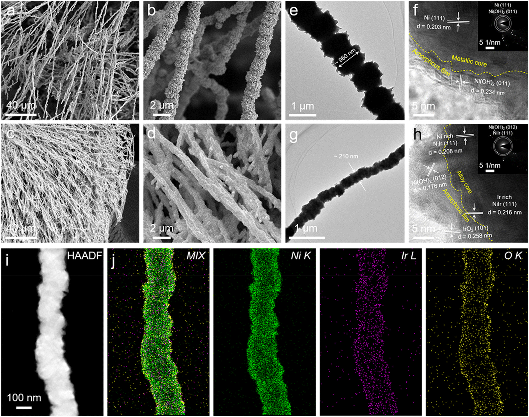 | ||
| Fig. 1 SEM images with different magnifications of (a and b) NiIr0 NCs, (c and d) NiIr1 NCs. TEM and HRTEM images with inset SAED images of (e and f) NiIr0 NCs, (g and h) NiIr1 NCs. HAADF-STEM image (i) and corresponding elemental mapping of Ir, Ni and O in NiIr1 NCs (j). | ||
The crystal structure of NiIrx NCs were further examined via X-ray diffraction (XRD) characterization. As shown in Fig. 2a, the characteristic peaks in NiIr0 NCs located at 44.7° and 52.1° are related to the (111) and (200) low-index crystal planes of Ni (JCPDS #70-0989). For NiIrx NCs (x = 0.01, 0.1, 0.5, 0.9, 1, 5, 10, 20), although the presence of Ir is clearly shown in the EDX results as discussed above, no diffraction peaks associated with the Ir or IrO2 phases are observed in the XRD pattern, which suggests that Ir is distributed atomically into the Ni lattice, or exists in the form of IrO2 clusters, rather than a highly ordered crystal phase. As can be clearly observed in NiIrx NCs (x = 0.01, 0.1, 0.5, 0.9, 1, 5, 10, 20) the diffraction peaks have negative shifts in different degrees. And negative shifts of 0.2 and 0.7° were observed in NiIr1 NCs and NiIr20 NCs, respectively. This is consistent with the fact that the volume expansion of the unit cell due to the incorporation of Ir into the Ni lattice to form the NiIr alloy solid solution, and the diffraction peak have negative shifts to lower 2θ values, which is consistent with HRTEM results.
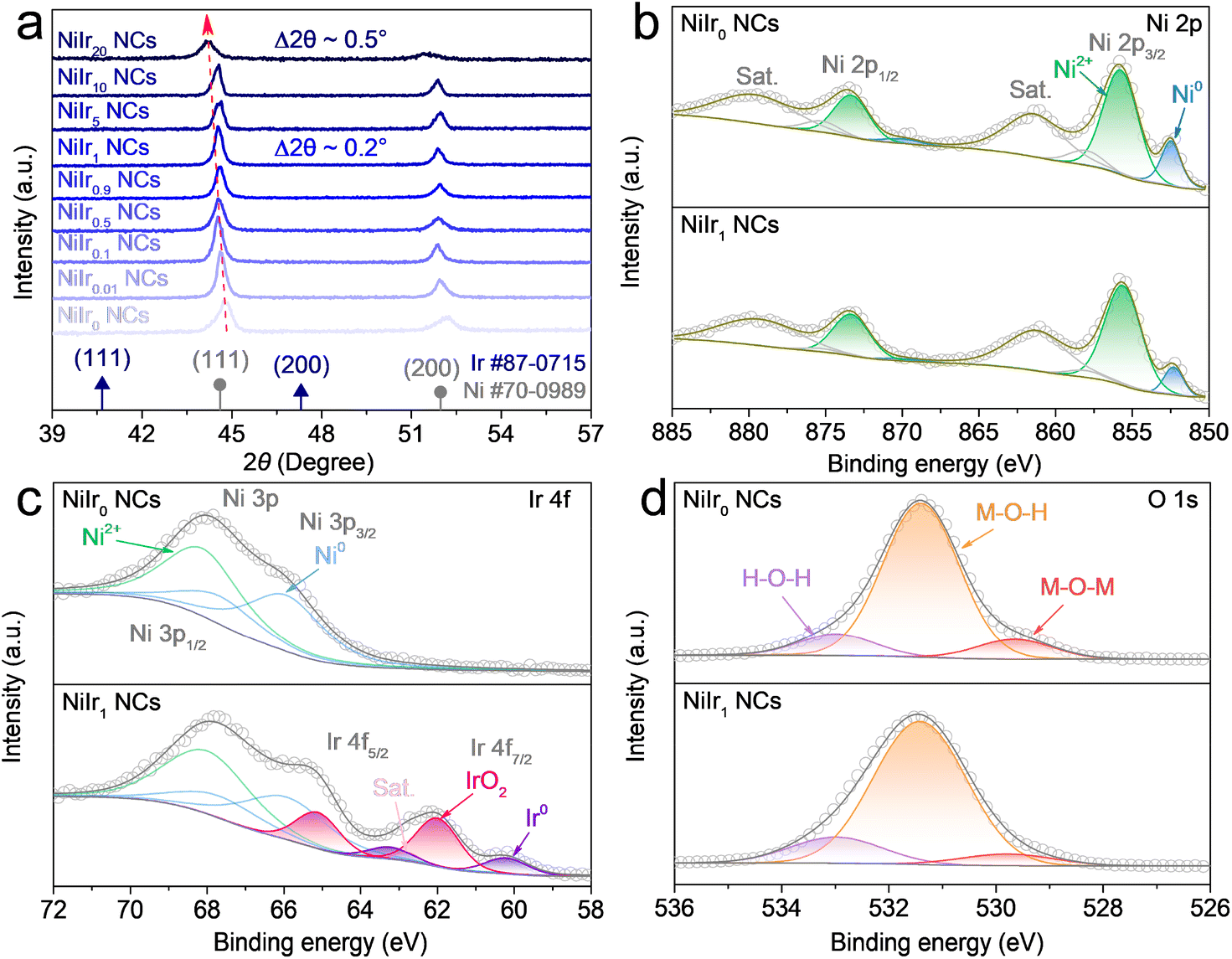 | ||
| Fig. 2 (a) XRD patterns of NiIrx NCs (x = 0, 0.01, 0.1, 0.5, 0.9, 1, 5, 10, 20). High-resolution XPS spectra of Ni 2p (b), Ir 4f (c) and O 1s (d) of NiIr0 NCs and NiIr1 NCs. | ||
The chemical states and surface species of NiIrx NCs (x = 0, 0.01, 0.1, 0.5, 0.9, 1, 10) are further investigated by X-ray photoelectron spectroscopy (XPS). As displayed in the wide-scan XPS survey in Fig. S5a,† the existence of Ni, Ir, C, and O elements is obviously observed. The binding energy positions of different species and the corresponding peak area data derived from the high-resolution XPS spectra of all elements are listed in Table S1.† As seen from the Ni 2p deconvolution spectra, a distinct Ni2+ phase, which belongs to Ni(OH)2, can be observed in all samples, and the presence of a metallic Ni phase can also be detected (Fig. 2b and S5b†). This further proves that Ni(OH)2 exists in the nanochain surface thin layer. The peaks of the metallic Ni phase are the most obvious in NiIr0 NCs and NiIr1 NCs, which also verifies that the thickness of the surface (hydr)oxide shell is within 10 nm, which is consistent with the TEM results. The deconvoluted XPS spectra of Ir 4f show that Ir exists in two oxidation states, Ir4+ and Ir0 representing the IrO2 and Ir metallic phases, respectively (Fig. 2c and S5c†).36–38 The surface Ir atomic ratio obtained from XPS shows that the Ir content in NiIrx NCs (x = 0, 0.01, 0.1, 0.5, 0.9, 1, 10) increases with the Ir doping amount (Table S1†), which are 0.00, 0.00, 0.02, 0.02, 0.19, 0.38 and 0.75 at%, respectively. The content of IrO2 is higher than that of the metallic Ir. This means the surface of NiIrx NCs are uniformly coated with (hydr)oxide shell, with little exposure of the internal metallic NiIrx core.
This further proves the existence of IrO2 in the (hydr)oxide shell on the surface of nanochains. Notably, no Ir signal can be detected in NiIr0.01 NCs and NiIr0.1 NCs, which may be due to the fact that the doping content is below the detection limit of XPS. The Ni 3p orbital partially overlaps with the Ir 4f orbital, also showing the presence of metallic Ni and Ni2+. The O 1s spectra (Fig. 2d and S5d†) further confirmed that the surface oxygen species of NiIrx NCs (x = 0, 0.01, 0.1, 0.5, 0.9, 1, 10) are mainly in the form of M–O–H (M = Ni) species39–41 with a low amount of M–O–M species (M = Ni and Ir) in the Ni(OH)2 and IrO2 lattice.42–44
Electrocatalytic activity toward OER, HER and OWS
The electrocatalytic performance of prepared NiIrx NCs (x = 0, 0.01, 0.1, 0.5, 0.9, 1, 5, 10, 20) was investigated in an electrolyte (1 M KOH) with a standard three-electrode system. As shown in the cyclic voltammetry (CV) curves, the OER overpotential plot at a current density of 10 mA cm−2 (η10) (Fig. 3a, S6a and c†), with the increase of Ir content in NiIrx NCs, η10 has a trend with great decrease first and then slowly increase. It is worth noting that since the SEM results show that the nanochains cannot grow well in NiIrx NCs (x = 5, 10, 20), the reason for the better performance when x = 5, 10, 20 may come from the increase of Ir content, which has higher intrinsic activity than Ni, rather than the exposure of more active sites by the nanochain array since the nanoparticles were dispersed on the surface of NF as discussed in SEM results. But such a high Ir content will cause a cost limit for large-scale applications. Therefore, NiIr1 NC was selected as the optimal sample. Interestingly, the η10 of NiIr1 NCs (253 mV) is significantly lower than that of NiIr0 NCs (363 mV) and also better than that of commercial IrO2 (300 mV). In addition, the current density of NiIr1 NCs at 1.6 V vs. RHE (189 mA cm−2) is four times higher than that of IrO2 (44 mA cm−2). This excellent OER activity may be attributed to both the interfacial effect between the surface Ni(OH)2/IrO2 thin film and the beneath metallic NiIrx core, which facilitates the charge transfer from the (hydr)oxide shell to the metallic NiIrx core, and the synergistic effect between Ni2+ and Ir4+ in the (hydr)oxide shell, which can regulate the local electronic configuration to optimize the adsorption and desorption energy of the OER intermediates.45–50 In contrast, although there is also an interface formed by Ni(OH)2 and Ni in NiIr0 NCs, Ir is missing and thus results in a lack of synergistic enhancement and the poor conductivity of Ni(OH)2.45,48 And similar reasons can also be found in IrO2 where the synergistic effect between Ni and Ir and the interface effect between IrO2/Ir are both absent. Since the OER mechanism is a complex four-electron transfer step, the Tafel slope is employed to theoretically analyze the rate-determining step (RDS) of the reaction on electrocatalysts. As shown in Fig. 3b and S6f,† NiIr1 NCs have a Tafel slope of 74.9 mV dec−1, which is smaller than that of NiIr0 NCs (75.8 mV dec−1) and IrO2 (109.4 mV dec−1). The other NiIrx NCs control groups have Tafel slopes close to 60 mV dec−1 (Fig. S6b and f†), which indicates that the OER process on NiIrx NCs has faster charge transfer and the RDS is the second step (*OH to *O).51,52 The RDS on IrO2 is the first electron transfer reaction.51 | ||
| Fig. 3 Electrochemical characterization in 1 M KOH electrolyte. (a) OER LSV curves of NiIr0 NCs, NiIr1 NCs and IrO2 at a scan rate of 5 mV s−1. (b) The corresponding OER Tafel slopes. (c) OER Nyquist plots. (d) HER LSV curves of NiIr0 NCs, NiIr1 NCs and Pt/C at a scan rate of 5 mV s−1. (e) The corresponding HER Tafel slopes. (f) HER Nyquist plots. (g) Calculations of Cdl for NiIr0 NCs and NiIr1 NCs. (h) OER CV curves before and after the durability test at a scan rate of 5 mV s−1. (i) OER chronopotentiometry test of NiIr1 NCs and the inset shows the three-electrode system used for the test. | ||
In addition to the interfacial effect, the fast charge transfer on NiIrx NCs also benefits from the in situ grown self-supporting structure, which makes a strong combination between nanochains and the support NF. Furthermore, since the η10 of NiIr0 NCs is much larger than that of NiIr1 NCs, the Nyquist plot shows that its OER charge transfer resistance (Rct) is much larger than that of NiIr1 NCs (Fig. 3c), which confirms the fast charge transfer on NiIr1 NCs. NiIr1 NCs also shows excellent OER durability with negligible potential change at current density of 200 mA cm−2 for 100 h (Fig. 3i). And the CV curves tested before and after the durability test overlap well in the OER part, except that the redox peaks belonging to Ni2+/3+ at 1.4 V vs. RHE are enhanced and shifted to the anodic direction after the durability test. This is due to the oxidation of Ni and the aging effect of Ni(OH)2 on the surface of the nanochain in the alkaline environment, which partially converts the redox couple of α-Ni(OH)2/γ-NiOOH to β-Ni(OH)2/β-NiOOH (Fig. 3h).53,54
To investigate the bifunctional properties of the prepared samples, the electrochemical HER test was also performed. As shown in the CV curve and η10 plot of HER (Fig. 3d, S6d and c†). Compared to NiIr0 NCs, the HER activities of NiIrx NCs (x = 0.01, 0.1, 0.5, 0.9, 1, 5, 10, 20) were improved. And the η10 of NiIr1 NCs (63 mV) is comparable to that of commercial 10 wt% Pt/C (49 mV). Interestingly, even trace amounts of Ir in NiIr alloy (NiIr0.01 NCs) can dramatically improve the HER activity. In addition, the HER activity of NiIrx NCs (x = 0.01, 0.1, 0.5, 0.9, 1) was observed to slowly increase with increasing Ir content. But when x = 5, 10 and 20, which is different from the OER case, the activity of NiIrx NCs decreased significantly. The η10 of NiIr5 NCs, NiIr10 NCs and NiIr20 NCs are 109, 86 and 86 mV, respectively. These findings indicate that Ir does not play a dominant role in the promotion of HER activity of NiIrx NCs. And this will be explained further below. The HER Tafel slopes of NiIrx NCs (x = 0, 0.01, 0.1, 0.5, 0.9, 1, 5, 10, 20) are all close to 120 mV dec−1 (Fig. 3e, S6e and f†), indicating that the Volmer step acts as the RDS.55 Notably, the estimated Tafel slope of NiIr1 NCs (96 mV dec−1) is significantly lower than those of NiIr0 NCs (139.5 mV dec−1) and NiIr5 NCs (142.7 mV dec−1). Since the Ir content does not dominate the HER, the large difference of the Tafel slope is most likely due to the difference in mass transfer rate, which affects the intermediate adsorption of the Volmer step. And NiIr1 NCs also had a smaller HER Rct than that of NiIr0 NCs (Fig. 3f). It can be seen from the insets of Fig. 3c and f that the solution resistance (Rs) for OER and HER are similar (about 1.5 Ω).
To further reveal the origin of the high HER activity, we characterized the ECSA of NiIr0 NCs and NiIr1 NCs (Fig. S7†). The results show that the double-layer capacitance (Cdl) of NiIr1 NCs (59.8 mF cm−2) is nearly 30 times higher than that of NiIr0 NCs (2.1 mF cm−2) (Fig. 3g). And Cdl is proportional to ECSA. As predicted from the SEM and TEM morphologies, the smaller nanochain diameter of NiIr1 NCs enables more nanochains to grow per unit area, resulting in a larger ECSA. In addition, the presence of Ir makes the nanochains grow thinner, so the HER η10 of NiIr0.01 NCs decreases abruptly compared with NiIr0 NCs. A further comparison of OER and HER performance on recently reported low noble-metal-based electrocatalysts is given in Table S2.†
By a combination of the outstanding OER and HER performance of NiIr1 NCs, benefiting from the unique self-supporting structure of nanochain arrays and reinforced with (hydr)oxide/metal interfacial effect and the synergistic effect between Ni and Ir (Fig. 4a), we tested the OWS performance in a two-electrode configuration using NiIr1 NCs as both the anode and cathode. As shown in Fig. 4b, the NiIr1 NCs//NiIr1 NCs electrode pair exhibited good OWS performance of small cell voltages of 1.481 and 1.769 V to deliver current densities of 10 and 100 mA cm−2, respectively. These cell voltages outperform the Pt/C//IrO2 electrode pair, which needs 1.570 and 1.975 V to achieve 10 and 100 mA cm−2, respectively. To eliminate the influence of side reactions such as oxygen reduction reaction (ORR) and hydrogen oxidation reaction (HOR), we also performed OWS tests of the NiIr1 NCs//NiIr1 NCs electrode pair in an H-type electrolysis cell separated by an anion exchange membrane (Fig. S8†). The results showed that its OWS activity has no significant difference with that in a normal electrolysis cell. It is worth noting that in a normal electrolysis cell, the current fluctuation in the high potential region due to gas diffusion is alleviated in the H-type electrolysis cell.56,57 More importantly, a negligible increase in cell voltage can be observed after 100 h durability test at a large current density of 500 mA cm−2 (Fig. 4c). In addition, as shown in Fig. 4b that the overpotentials achieved from LSV curves of OWS before and after durability testing only has a slight increase of ∼7 mV for both 10 and 100 mA cm−2, which is within the error range. From the SEM images of NiIr1 NCs which were employed as anode after the durability test (Fig. S3a† and 4d), it can be seen that the self-supporting nanochain arrays are well preserved, the high magnification image shows the surface of the nanochain becomes rough (Fig. 4d), which may be due to the oxidation of Ni and the aging effect of Ni(OH)2 during the OER process as discussed above. And according to the EDX analysis, the atomic ratio of O after the durability test was increased to 6.25 at% (Fig. S3†), which is higher than that of freshly prepared (2.22 at%). Furthermore, the ICP-MS results (Table S3†) of the electrolyte after 100 h OWS stability test showed that only trace amounts of Ni (58.3 ppb) and Ir (1.6 ppb) ions were present in the electrolyte, further demonstrating the excellent electrochemical stability of NiIr1 NCs.
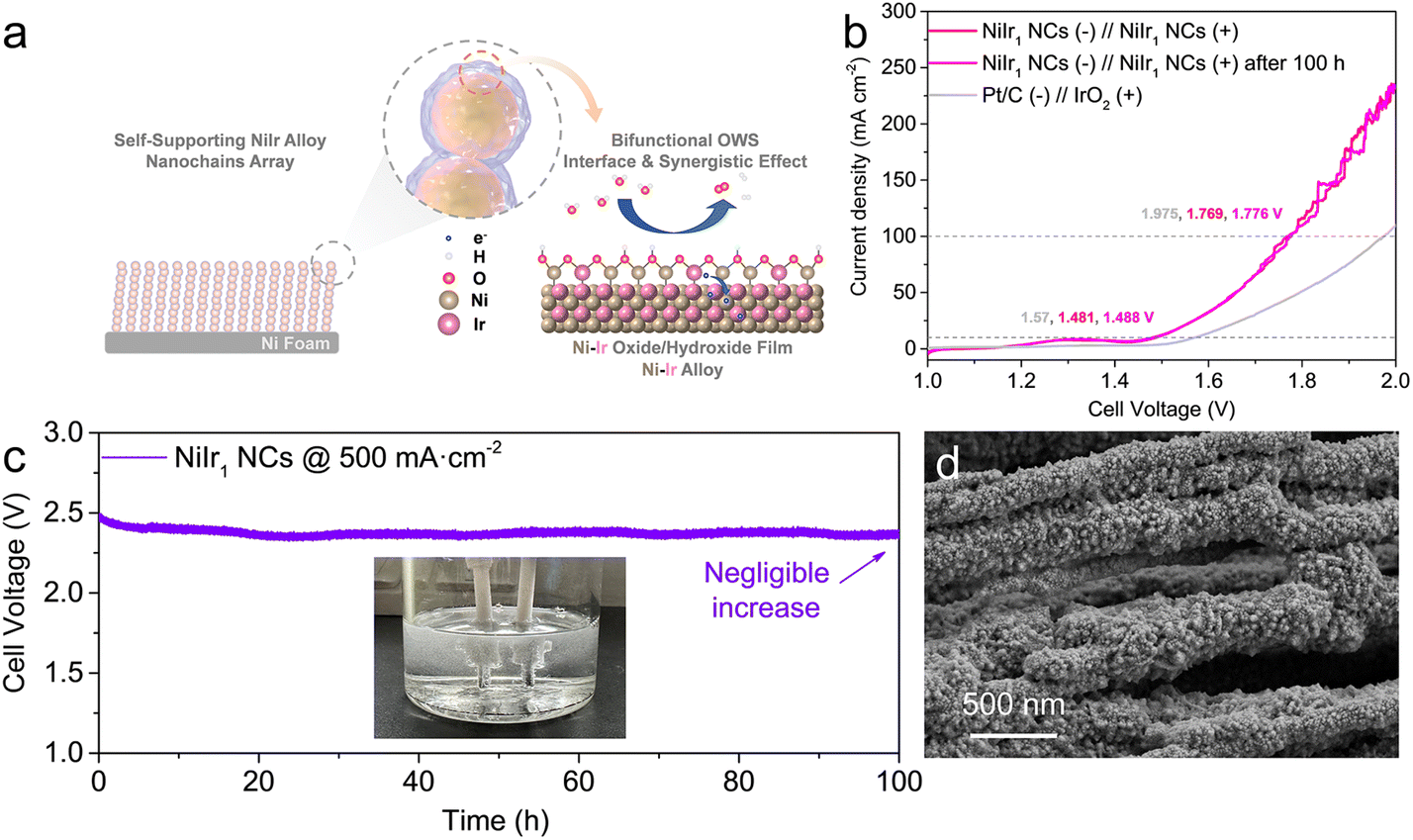 | ||
| Fig. 4 (a) Schematic illustration of the nanochains array electrode with self-supported three-dimensional core–shell structure and the bifunctional OWS process. (b) OWS LSV curves before and after the durability test at a scan rate of 5 mV s−1. (c) OWS chronopotentiometry test of NiIr1 NCs (−)//NiIr1 NCs (+) electrode pair the inset shows the two-electrode configuration used for the tests. (d) High magnification SEM image of NiIr1 NCs serves as anode after 100 h OER process. | ||
Conclusions
In summary, this work highlights the designs of a self-supporting ultralow-iridium containing NiIrx NCs with three-dimensional core–shell structure for efficient OWS. This unique structure has high ECSA, thus the active sites can be fully exposed and facilitate the mass transfer. And the in situ-growth of alloy nanochain arrays also provide high structural stability and good conductivity. In addition, NiIrx NCs have bifunctional properties that can not only promote the OER activity, but also the HER. Especially, the OER activity (electrode geometrical area) of NiIr1 NCs is four times higher than that of commercial IrO2 at 1.6 V vs. RHE, and the HER η10 (63 mV) is comparable to that of 10 wt% Pt/C. A thin amorphous (hydr)oxide shell (5–10 nm) can arouse the interfacial effect with the metallic NiIrx core (e.g., IrO2/NiIrx and Ni(OH)2/NiIrx). And combining with the synergistic effect between Ni2+ and Ir4+ in the (hydr)oxide shell, the excellent electrocatalytic can be achieved. Furthermore, NiIr1 NCs exhibited excellent OER durability (100 h @ 200 mA cm−2) and excellent OWS durability (100 h @ 500 mA cm−2). These findings represent a possible advance towards the low-cost, high-efficiency, and high-durability bifunctional electrocatalysts for large-scale OWS applications.Conflicts of interest
There are no conflicts to declare.Acknowledgements
The work was financially supported by the Carbon Peak & Carbon Neutrality Project (Grant Number: 21DZ1207900). The National Natural Science Foundation of China (Grant Number: 21902011). The Natural Science Foundation of Shanghai (Grant Number: 22ZR1471900). The Shanghai Qimingxing Project (Grant Number: 22QA1410300).Notes and references
- S. Chu and A. Majumdar, Nature, 2012, 488, 294–303 CrossRef CAS PubMed.
- C. Hu, L. Zhang and J. Gong, Energy Environ. Sci., 2019, 12, 2620–2645 RSC.
- S. Sultan, J. N. Tiwari, A. N. Singh, S. Zhumagali, M. Ha, C. W. Myung, P. Thangavel and K. S. Kim, Adv. Energy Mater., 2019, 9, 1900624 CrossRef.
- S. Chandrasekaran, M. Khandelwal, F. Dayong, L. Sui, J. S. Chung, R. D. K. Misra, P. Yin, E. J. Kim, W. Kim, A. Vanchiappan, Y. Liu, S. H. Hur, H. Zhang and C. Bowen, Adv. Energy Mater., 2022, 12, 2200409 CrossRef CAS.
- C. Pang, X. Ma, Y. Wu, S. Li, Z. Xu, M. Wang and X. Zhu, RSC Adv., 2022, 12, 22931–22938 RSC.
- S. M. Alia, B. Rasimick, C. Ngo, K. Neyerlin, S. S. Kocha, S. Pylypenko, H. Xu and B. S. Pivovar, J. Electrochem. Soc., 2016, 163, F3105 CrossRef CAS.
- S. M. Alia, S. Shulda, C. Ngo, S. Pylypenko and B. S. Pivovar, ACS Catal., 2018, 8, 2111–2120 CrossRef CAS.
- K. Neyerlin, W. Gu, J. Jorne and H. A. Gasteiger, J. Electrochem. Soc., 2007, 154, B631 CrossRef CAS.
- P. Farràs, P. Strasser and A. J. Cowan, Joule, 2021, 5, 1921–1923 CrossRef.
- S. A. Grigoriev, V. N. Fateev, D. G. Bessarabov and P. Millet, Int. J. Hydrogen Energy, 2020, 45, 26036–26058 CrossRef CAS.
- Z.-Y. Yu, Y. Duan, X.-Y. Feng, X. Yu, M.-R. Gao and S.-H. Yu, Adv. Mater., 2021, 33, 2007100 CrossRef CAS PubMed.
- S. Chandrasekaran, D. Ma, Y. Ge, L. Deng, C. Bowen, J. Roscow, Y. Zhang, Z. Lin, R. D. K. Misra, J. Li, P. Zhang and H. Zhang, Nano Energy, 2020, 77, 105080 CrossRef CAS.
- R. Ramachandran, T.-W. Chen, P. Veerakumar, G. Anushya, S.-M. Chen, R. Kannan, V. Mariyappan, S. Chitra, N. Ponmurugaraj and M. Boominathan, RSC Adv., 2022, 12, 28227–28244 RSC.
- G. Fu and J.-M. Lee, J. Mater. Chem. A, 2019, 7, 9386–9405 RSC.
- A. Parra-Puerto, K. L. Ng, K. Fahy, A. E. Goode, M. P. Ryan and A. Kucernak, ACS Catal., 2019, 9, 11515–11529 CrossRef CAS.
- D. S. Raja, X.-F. Chuah and S.-Y. Lu, Adv. Energy Mater., 2018, 8, 1801065 CrossRef.
- F. Zheng, W. Zhang, X. Zhang, Y. Zhang and W. Chen, Adv. Funct. Mater., 2021, 31, 2103318 CrossRef CAS.
- J. Zhou, Y. Wang, X. Su, S. Gu, R. Liu, Y. Huang, S. Yan, J. Li and S. Zhang, Energy Environ. Sci., 2019, 12, 739–746 RSC.
- S. Cherevko, S. Geiger, O. Kasian, N. Kulyk, J.-P. Grote, A. Savan, B. R. Shrestha, S. Merzlikin, B. Breitbach, A. Ludwig and K. J. J. Mayrhofer, Catal. Today, 2016, 262, 170–180 CrossRef CAS.
- R. V. Genova-Koleva, F. Alcaide, G. Álvarez, P. L. Cabot, H.-J. Grande, M. V. Martínez-Huerta and O. Miguel, J. Energy Chem., 2019, 34, 227–239 CrossRef.
- R. Li, H. Wang, F. Hu, K. C. Chan, X. Liu, Z. Lu, J. Wang, Z. Li, L. Zeng, Y. Li, X. Wu and Y. Xiong, Nat. Commun., 2021, 12, 3540 CrossRef CAS PubMed.
- Z. Cui and R. Qi, Appl. Surf. Sci., 2021, 554, 149591 CrossRef CAS.
- R. Samanta, P. Panda, R. Mishra and S. Barman, Energy Fuels, 2022, 36, 1015–1026 CrossRef CAS.
- X. Zhao, Y. Chang, J. Ji, J. Jia and M. Jia, RSC Adv., 2021, 11, 33179–33185 RSC.
- W.-H. Lai, L.-F. Zhang, W.-B. Hua, S. Indris, Z.-C. Yan, Z. Hu, B. Zhang, Y. Liu, L. Wang, M. Liu, R. Liu, Y.-X. Wang, J.-Z. Wang, Z. Hu, H.-K. Liu, S.-L. Chou and S.-X. Dou, Angew. Chem., Int. Ed., 2019, 58, 11868–11873 CrossRef CAS PubMed.
- Q. Wang, X. Huang, Z. L. Zhao, M. Wang, B. Xiang, J. Li, Z. Feng, H. Xu and M. Gu, J. Am. Chem. Soc., 2020, 142, 7425–7433 CrossRef CAS PubMed.
- J. Liu, J. Xiao, Z. Wang, H. Yuan, Z. Lu, B. Luo, E. Tian and G. I. N. Waterhouse, ACS Catal., 2021, 11, 5386–5395 CrossRef CAS.
- X. Yang, Y. Liu, R. Guo and J. Xiao, Chem. Rec., 2022, e202200176 CAS.
- Y. Tong, H. Mao, Q. Sun, P. Chen, F. Yan and J. Liu, ChemCatChem, 2020, 12, 5720–5726 CrossRef CAS.
- S. Trasatti, J. Electroanal. Chem. Interfacial Electrochem., 1972, 39, 163–184 CrossRef CAS.
- Q. Wang, C.-Q. Xu, W. Liu, S.-F. Hung, H. B. Yang, J. Gao, W. Cai, H. M. Chen, J. Li and B. Liu, Nat. Commun., 2020, 11, 4246 CrossRef CAS PubMed.
- Z.-J. Wang, M.-X. Li, J.-H. Yu, X.-B. Ge, Y.-H. Liu and W.-H. Wang, Adv. Mater., 2020, 32, 1906384 CrossRef CAS PubMed.
- P. Huang, P. Zhang, S. Xu, H. Wang, X. Zhang and H. Zhang, Nanoscale, 2020, 12, 2309–2327 RSC.
- A. Hirohata, T. Huminiuc, J. Sinclair, H. Wu, M. Samiepour, G. Vallejo-Fernandez, K. O'Grady, J. Balluf, M. Meinert, G. Reiss, E. Simon, S. Khmelevskyi, L. Szunyogh, R. Y. Díaz, U. Nowak, T. Tsuchiya, T. Sugiyama, T. Kubota, K. Takanashi, N. Inami and K. Ono, J. Phys. D: Appl. Phys., 2017, 50, 443001 CrossRef.
- F. Godínez-Salomón, L. Albiter, S. M. Alia, B. S. Pivovar, L. E. Camacho-Forero, P. B. Balbuena, R. Mendoza-Cruz, M. J. Arellano-Jimenez and C. P. Rhodes, ACS Catal., 2018, 8, 10498–10520 CrossRef.
- P. A. Zhdan, G. K. Boreskov, W. F. Egelhoff and W. H. Weinberg, Surf. Sci., 1976, 61, 377–390 CrossRef CAS.
- X. Zhou, I. Hwang, O. Tomanec, D. Fehn, A. Mazare, R. Zboril, K. Meyer and P. Schmuki, Adv. Funct. Mater., 2021, 31, 2102843 CrossRef CAS.
- R. Badam, M. Hara, H.-H. Huang and M. Yoshimura, Int. J. Hydrogen Energy, 2018, 43, 18095–18104 CrossRef CAS.
- A. N. Mansour, Surf. Sci. Spectra, 1994, 3, 239–246 CrossRef CAS.
- A. N. Mansour and C. A. Melendres, Surf. Sci. Spectra, 1994, 3, 255–262 CrossRef CAS.
- X. Yan, L. Tian and X. Chen, J. Power Sources, 2015, 300, 336–343 CrossRef CAS.
- S. J. Freakley, J. Ruiz-Esquius and D. J. Morgan, Surf. Interface Anal., 2017, 49, 794–799 CrossRef CAS.
- Y. Sun, Y. Li, S. You, X. Li, Y. Zhang, Z. Cai, M. Liu, N. Ren and J. Zou, Chem. Eng. J., 2021, 424, 130460 CrossRef CAS.
- F.-F. Zhang, C.-Q. Cheng, J.-Q. Wang, L. Shang, Y. Feng, Y. Zhang, J. Mao, Q.-J. Guo, Y.-M. Xie and C.-K. Dong, ACS Energy Lett., 2021, 6, 1588–1595 CrossRef CAS.
- M. Bernt, C. Schramm, J. Schröter, C. Gebauer, J. Byrknes, C. Eickes and H. A. Gasteiger, J. Electrochem. Soc., 2021, 168, 084513 CrossRef CAS.
- K. Conder, Electronic and ionic conductivity in metal oxides, Paul Scherrer Institute, Switzerland, 2012, pp. 1–44 Search PubMed.
- Z. Liu, G. Wang, J. Guo, S. Wang and S.-q. Zang, Nano Res., 2023, 16, 334–342 CrossRef CAS.
- S. A. Mahmoud, S. M. Al-Shomar and A. A. Akl, Adv. Condens. Matter Phys., 2010, 2010, 518209 Search PubMed.
- Y. Xu, M. Liu, M. Wang, T. Ren, K. Ren, Z. Wang, X. Li, L. Wang and H. Wang, Appl. Catal., B, 2022, 300, 120753 CrossRef CAS.
- H. You, D. Wu, D. Si, M. Cao, F. Sun, H. Zhang, H. Wang, T.-F. Liu and R. Cao, J. Am. Chem. Soc., 2022, 144, 9254–9263 CrossRef CAS PubMed.
- N.-T. Suen, S.-F. Hung, Q. Quan, N. Zhang, Y.-J. Xu and H. M. Chen, Chem. Soc. Rev., 2017, 46, 337–365 RSC.
- L. Tang, T. Fan, Z. Chen, J. Tian, H. Guo, M. Peng, F. Zuo, X. Fu, M. Li, Y. Bu, Y. Luo, J. Li and Y. Sun, Chem. Eng. J., 2021, 417, 129324 CrossRef CAS.
- S. Klaus, Y. Cai, M. W. Louie, L. Trotochaud and A. T. Bell, J. Phys. Chem. C, 2015, 119, 7243–7254 CrossRef CAS.
- M. W. Louie and A. T. Bell, J. Am. Chem. Soc., 2013, 135, 12329–12337 CrossRef CAS PubMed.
- C. G. Morales-Guio, L.-A. Stern and X. Hu, Chem. Soc. Rev., 2014, 43, 6555–6569 RSC.
- B. Bernard, S. Huaneng, P. Sivakumar and L. Vladimir, in Electrolysis, ed. L. Vladimir and K. Janis, IntechOpen, Rijeka, 2012, ch. 3, DOI:10.5772/52947.
- X. Xie, L. Du, L. Yan, S. Park, Y. Qiu, J. Sokolowski, W. Wang and Y. Shao, Adv. Funct. Mater., 2022, 32, 2110036 CrossRef CAS.
Footnote |
| † Electronic supplementary information (ESI) available. See DOI: https://doi.org/10.1039/d3ra01845h |
| This journal is © The Royal Society of Chemistry 2023 |