
 Open Access Article
 This Open Access Article is licensed under a Creative Commons Attribution-Non Commercial 3.0 Unported Licence
Proton conducting metal–organic frameworks with light response for multistate logic gates†
Kainan Xuea,
Shabab Hussaina,
Shuaikang Fana and
Xinsheng Peng *ab
*ab
aState Key Laboratory of Silicon Materials, School of Materials Science and Engineering, Zhejiang University, Hangzhou 310027, P. R. China. E-mail: pengxinsheng@zju.edu.cn
bWenzhou Key Laboratory of Novel Optoelectronic and Nanomaterials, Institute of Wenzhou, Zhejiang University, Wenzhou 325006, P. R. China
First published on 24th April 2023
Abstract
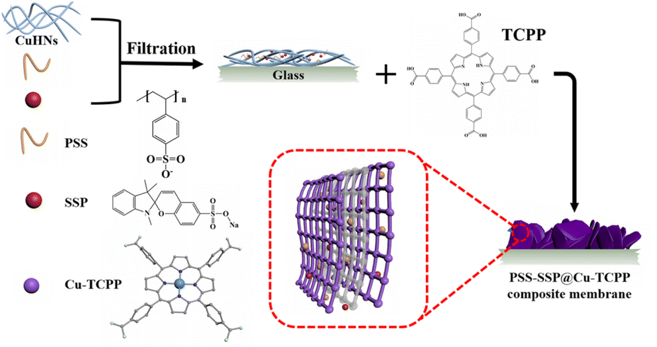
The simulation of neurons receiving stimulation and transmitting signals by proton conduction has great potential applications in electrochemistry and biology. In this work, copper tetrakis(4-carboxyphenyl)porphyrin (Cu-TCPP), which is a proton conductive metal organic framework (MOF) with photothermal response, is adopted as the structural framework, with the in situ co-incorporation of polystyrene sulfonate (PSS) and sulfonated spiropyran (SSP) to prepare the composite membranes. The resultant PSS–SSP@Cu-TCPP thin-film membranes were used as the logic gates i.e., NO gate, NOR gate and NAND gate because of the photothermal effect of Cu-TCPP MOFs and the photoinduced conformational changes of SSP. This membrane exhibits the high proton conductivity of 1.37 × 10⁻⁴ S cm−1. Under the conditions of 55 °C and 95% relative humidity (RH), using 405 nm laser irradiation with 400 mW cm−2 and 520 nm laser irradiation with 200 mW cm−2 as inputs, the device can be adjusted between various steady states, and the value of the conductivity is regarded as the output with different thresholds in different logic gates. Before and after laser irradiation, the electrical conductivity changes dramatically, and the ON/OFF switching ratio reached 1068. The application of three logic gates is realized by constructing circuits with LED lights. Depending on the convenience of light and the easy measurement of conductivity, this kind of device with light source as input and electrical signal as output provides the possibility to realize the remote control of chemical sensors and complex logic gates devices.
Introduction
In biological neuron systems, the transmission and reception of information (called electrical impulses) mainly depends on the transportation and interaction of ions and neurotransmitters.1–5 The transmission and reception of information in the axon of neurons mainly depends on the proton transmission.6 Proton hopping is the fastest chemical reaction, while only relying on the slow diffusion of sodium and potassium ions, which cannot achieve the fast transmission of information.7 In order to study and mimic the work of biological brains and neurons, materials that can receive external stimuli and convert them into electrical signals are essential. Therefore, this biomimetic material has great prospects in the field of electrochemistry, biology and bionics. In recent years, such materials have been widely used in energy conversion, biosensing, etc.8–9The mechanism of proton conduction has been extensively studied and has a relatively mature theoretical basis.10–13 Among many solid materials with proton conducting, metal organic frameworks (MOFs) have attracted the attention of researchers due to their high porosity, large specific surface area, adjustable pore size and diverse structure.14–15 Due to these advantages, there are potential opportunities for MOFs in catalysis,16 fuel cells,17 gas separation,18 optoelectronic devices,19 and medicine.20 Recently, many researchers used light, heat voltage or ions, such as Fe3+, Ag+, Na+ as input stimulus, and output in other forms of signals, such as color, fluorescence etc.21–26 Although these signals have the advantages of obvious phenomena and easy observation by eye, they are not conducive to the further input of signals and find difficult in achieving continuous transmission between signals. Therefore, MOFs with electrical signals, such as electrical conductivity have attracted certain attention. On the one hand, MOFs with electrical signals as output are easier to be captured by instruments, easy to quantify and free from interference. On the other hand, the output electrical signal can be further used as the input source for the next reaction, which is in favor of the transmission of more complex information.27 By introducing specific objects into the framework of MOFs, the proton transport ability can be improved. As the most basic signals, logic gates can be combined to achieve specific requirements, it is necessary to design basic logic gates. The design of most logic gates requires two or more inputs to realize the possibility of multiple stable states. Light source, as a simple, convenient and easily regulated external stimulus, has been used in many studies of logic gate design.28–29 The design of materials should also be reversible after being stimulated by inputs, such as light source to achieve repeated application of materials. Therefore, the proton-conducting MOF with optical signal as input and electrical signal as output is desirable.27–30 In the proton conduction of the MOF, there are usually certain requirements regarding humidity and temperature to ensure proton conduction.29,31
In recent years, copper tetrakis(4-carboxyphenyl)porphyrin (Cu-TCPP), as an optical response MOFs for proton conduction, has received attention in the design of logic gate circuits.32 Cu-TCPP is formed by the coordination of Cu2+ ions and porphyrin, which is a famous light responsive precursor, and provides the basis of photothermal reaction for Cu-TCPP.33 Benefitting from a large number of dangling COOH groups and good water absorption, Cu-TCPP is a proton-conducting MOF with good photothermal effect.34 Because of the d–d energy band transition of Cu2+ ions, the nanosheets have strong near-infrared absorption.35–36 When Cu-TCPP is irradiated by visible light, the local temperature rises tremendously, so that the water molecules in the void/pore escape without destroying the crystal structure and affecting the conduction of protons. At the same time, in the absence of a light source, the water molecules re-enter the void/pore and realize reversible changes.32 This kind of photothermal effect can realize simple switching function, which has great advantages for remote control. Polystyrene sulfonate (PSS) is a linear polymer with a large number of SO3− groups, with an average of 4 SO3− groups within 1 nm, can enhance the conductivity of thin membranes when loaded into MOFs.37 As a photochromic dye, sulfated spiropyran (SSP) has the characteristics of photoinduced structural changes, and the reversible transformation between the two structures can be achieved under the irradiation of about 506 nm and 368 nm light, with fast response speed.38–43 The different groups before and after the two forms affect the proton transport efficiency.44 If SSP is loaded into Cu-TCPP, it can not only promote proton conduction within the MOFs framework, but also control the conductivity and realize the function of light controlled switch.
In order to realize the construction of multistate logic gates, in this paper, SSP and PSS were co-loaded into Cu-TCPP, and 405 nm and 520 nm lasers are used as input sources to construct a composite membrane device with optical response and proton conduction. When the membrane is placed at 55 °C and 95% relative humidity (RH) in the dark, the conductivity of the composite membrane is 1.37 × 10⁻⁴ S cm−1; when the composite membrane is irradiated by a 405 nm laser irradiation with 400 mW cm−2, the conductivity decreases and the switching ratio is 62.8. Under 520 nm laser irradiation with 200 mW cm−2 irradiation, the switching ratio is 93.6, and when both light sources are illuminated at the same time, the switching ratio is 1068. When light is removed, the conductivity reversibly returns to its original dark state. The large change in conductivity when changing the input source makes it possible to implement logic gates. According to the Boolean logic language, we design the corresponding circuits and use the device to realize the function of three logic gates (NO gate, NOR gate, and NAND gate), and further prove the realization of the function by light-emitting diode (LED).
Experimental section
Materials and reagents
Cupper II nitrate trihydrate [Cu(NO3)2·3H2O] and 1,2,3,3-tetramethyl-3H-indolium iodide were bought from Sigma-Aldrich. Tetrakis(4-carboxyphenyl)porphyrin (TCPP), 2-aminoethanol (AE), and polystyrene sulfonate (PSS) were bought from Aladdin. Dimethyl formamide, ethanol, ethyl ether, benzene, chloroform, piperidine and methanol were purchased from Merck. Sodium salicylaldehyde-5-sulfonate was bought from Jilin Forest Science and Technology Co., Ltd. Polycarbonate (PC) membranes with a pore diameter of 200 nm and an effective diameter of 20 mm were provided by Whatman and were used to filter the precursors. Ultrapure water of 18.2 MΩ was obtained from Millipore direct-Q system and was used in all the experiments. All reagents and solvents were used as received.Synthesis of PSS–SSP@Cu-TCPP composite membranes
PSS–SSP@Cu-TCPP MOFs was synthesized by in situ solid-confinement method employing copper hydrogen nanostrands (CuHNs) as metallic source. Briefly, Cu(NO3)2·3H2O (4 mM) and AE (1.4 mM) aqueous solutions were mixed in a breaker and stirred for 10 min and then left standing for 12 h at room temperature to synthesize the CuHNs. PSS and SSP aqueous solutions with a concentration of 1 mg mL−1 were also prepared for the in situ loading. 30 mL of CuHNs suspension with a specified amount of PSS and SSP solution were first mixed evenly and then filtered out on a PC membrane with a pore size of 200 nm using pressure filtration assembly. The detailed information of PSS and SSP amount (mL) is mentioned in the Table S1 (ESI†). After filtration, the resulted PSS–SSP loaded CuHNs were transferred to the glass-substrate using ethanol. Next, the CuHNs thin layer was immersed in a sealed glass Petri dish containing 4 mL TCPP solution (0.005 mM, dissolved in 4 mL of DMF and ethanol with a volume ratio of 3![[thin space (1/6-em)]](https://www.rsc.org/images/entities/char_2009.gif) :1). The Petri dish was placed in the already hot oven for 24 h at 80 °C. Finally, the PSS–SSP@Cu-TCPP composite membranes were obtained and washed with ethanol for several times. Referred to Table S1,† the different Cu-TCPP composite membranes are named as Cx–y, where x and y represent the amount (mL) of PSS and SSP, respectively. The whole process of membrane preparation is shown schematically in the Scheme 1.
:1). The Petri dish was placed in the already hot oven for 24 h at 80 °C. Finally, the PSS–SSP@Cu-TCPP composite membranes were obtained and washed with ethanol for several times. Referred to Table S1,† the different Cu-TCPP composite membranes are named as Cx–y, where x and y represent the amount (mL) of PSS and SSP, respectively. The whole process of membrane preparation is shown schematically in the Scheme 1.
 | ||
| Scheme 1 Schematic illustration of the synthesis of PSS–SSP@Cu-TCPP composite membranes. | ||
Characterization and instruments
The morphologies of Cu-TCPP pristine and composite membranes were characterized by scanning electron microscopy (SEM) [SU-70/Hitachi S-4800] equipped with X-ray energy dispersive analysis and TEM (Ht7700). The zeta potential of the pristine Cu-TCPP and PSS–SSP@Cu-TCPP ethanolic dispersion were measured by Zetasizer Nano-ZS [Malvern, UK]. The X-ray diffraction (XRD) patterns of the composite membranes were assessed through X'Pert PRO [PANalytical, The Netherlands] with Cu Kα radiation from 3.0 to 50.0° with 0.02° step. The Fourier transform infrared (FTIR) spectrum were recorded from 400 cm−1 to 4000 cm−1 frequency range with KBr pellets by FTIR TENSOR 27 equipment. The X-ray photoelectron spectroscopy (XPS, Thermo Fisher Scientific ESCALAB Xi+) was employed to confirm the existence of PSS and SSP. The N2 sorption isotherms were recorded by Micromeritics instrument (ASAP-2460) at 88 K. The ultraviolet-visible (UV-Vis) spectrum of the MOFs ethanolic dispersion was recorded by a UV-Vis spectrophotometer [Shimadzu UV-3600]. UV-Vis-near infrared (UV-Vis-NIR) spectrums of the composite membrane were assessed through a UV-Vis-NIR spectrophotometer [Agilent Cary5000] and the solar absorption percentage (A) was obtained according to the following eqn (1):| A = 1 − R − T | (1) |
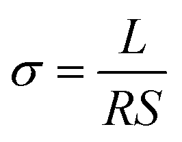
Conductivity measurement
Silver electrodes (three pairs) were evaporated onto the surface of the resulted composite membranes using electrodes preparation system [Beijing Technol Co. Ltd, China] with a current of 65 A for 30 min. The silver glue was used to connect the silver electrodes with the copper wires (refer to Fig. S1(c)†). In order to measure the conductivity of the composite membranes under different conditions, electrochemical workstation [CHI 660D, Shanghai, China] was employed to measure the alternating current (AC) impedance in the frequency range of 100 Hz to 1 MHz with AC amplitude of 0.1 V. Programmable temperature and humidity controller (BC1300, Shanghai YIHENG) was used to achieve the constant temperatures and humidity. The programmable controller was given a time of at least 3 h to stabilize the required temperature and humidity. Different light sources e.g., visible light source (Perfect Light), ultraviolet laser (405 nm) and green lasers (520 nm) were placed outside the temperature and humidity controller's window to pass the required light. The optical power density was determined by PLS-MW2000 (Perfect Light). The conductivity values were measured after 10 min of the sample's light irradiation.The protonic conductivity (σ) of the membrane was calculated by the following eqn (2):
 | (2) |
Results and discussion
Morphological and structural characterization
Fig. 1(a) shows the surface morphology of pristine CuHNs, which were used as Cu metallic source. The CuHNs present longer strip shaped structures with length of several micrometers. The PSS–SSP loaded CuHNs present similar morphology to that of pristine ones with no significant differences as shown in Fig. 1(d). After chemical reaction of TCPP ligand with the Cu2+, the pristine Cu-TCPP and PSS–SSP@Cu-TCPP MOFs are synthesized on the top of the glass substrate with average MOFs layer thickness 10.9 and 8.1 μm shown in Fig. 1(b), (c) and (e), (f), respectively. The surface of the pristine Cu-TCPP membrane “C0–0” is iso-structural to the PSS–SSP@Cu-TCPP membrane “C1–1”, with well intergrown MOFs nanosheets. The surface morphologies of all the membranes i.e., C0–0, C1–0, and C1–1 are similar, exhibiting smooth petal-like nanosheets structures Fig. 1(b), (e) and S1(a).† Moreover, the TEM images also confirm the ultrathin nature of pristine Cu-TCPP and PSS–SSP@Cu-TCPP MOFs nanosheets Fig. 1(g) and (h). The addition of PSS and SSP has no significant morphological influences on the nanosheets morphology. In addition, these membranes exhibit better interface contact with the silver (Ag) electrodes Fig. 1(i) and (inserted). The EDX elemental mapping illustrates the uniform distribution of constituting elements i.e., C, O, N and Cu of the Cu-TCPP MOFs. The existence and uniform distribution of S in the C1–1 membrane additionally confirm the successful loading of PSS and SSP, Fig. S1(d) and (e).† Furthermore, the zeta potential of C0–0 i.e., −3.23 mV negatively increased to −13.1 mV, ascribed to the more electronegative PSS and SSP, resultingly makes the C1–1 composite membrane more negative Fig. S2(a) and (b).† | ||
| Fig. 1 (a) SEM surface and corresponding cross-sectional images of (a) pristine CuNHs; (b) and (c) pristine Cu-TCPP membrane “C0–0”; (d) PSS–SSP@CuNHs, (e) and (f) PSS–SSP@Cu-TCPP membrane “C1–1”; TEM images of (g) C0–0; (h) C1–1 and (i) SEM surface image of C1–1 membrane with deposited Ag electrodes (the picture of C1–1 membrane with attached Ag electrodes). | ||
Fig. 2(a) and S3(a)† shows the XRD patterns of Cu-TCPP composite membranes. All patterns show distinct peaks at 7.5°, 12° and 19.4°. The peak at 19.4° corresond to the (004) plane evincing the layered crystal structure of Cu-TCPP. While the incorporation of PSS and SSP does not affect the crystal structure of Cu-TCPP composite membranes. FTIR spectra shows two distinct peaks at 1402 and 1605 cm−1 correspond to the O![[double bond, length as m-dash]](https://www.rsc.org/images/entities/char_e001.gif) C–O–Cu bonds, proving successful coordination between TCPP ligand and Cu2+ ions Fig. 2(b). This co-ordinate covalent bond is further verified by XPS Cu deconvoluted peaks at 933.1 eV and 953.1 eV representing Cu–O bonds. While the emerging peak at 1049 cm−1 corresponds to the SO symmetric stretching vibrations of SO3− groups of PSS and SSP. Moreover, a characteristic peak appeared at 1095 cm−1 in the SSP loading membranes correspond to the C–O bonds of SSP. The existence of PSS and SSP can be further verified by XPS. The peaks at 168.2 and 163.9 eV correspond to the S 2p1/2 and 2p3/2, respectively Fig. 2(c). According to Fig. 2(d) and (e), the porosity of Cu-TCPP nanosheets were evaluated by N2 adsorption–desorption experiments. The pristine and PSS–SSP incorporated MOFs displayed similar type-I Langmuir isotherms with BET surface area of 127.8 m2 g−1 and 54.4 m2 g−1. Moreover, the pore size distribution data in Fig. 2(e) and S3(d)† shows that the Cu-TCPP and PSS–SSP@Cu-TCPP have macro and mesoporous structure.
C–O–Cu bonds, proving successful coordination between TCPP ligand and Cu2+ ions Fig. 2(b). This co-ordinate covalent bond is further verified by XPS Cu deconvoluted peaks at 933.1 eV and 953.1 eV representing Cu–O bonds. While the emerging peak at 1049 cm−1 corresponds to the SO symmetric stretching vibrations of SO3− groups of PSS and SSP. Moreover, a characteristic peak appeared at 1095 cm−1 in the SSP loading membranes correspond to the C–O bonds of SSP. The existence of PSS and SSP can be further verified by XPS. The peaks at 168.2 and 163.9 eV correspond to the S 2p1/2 and 2p3/2, respectively Fig. 2(c). According to Fig. 2(d) and (e), the porosity of Cu-TCPP nanosheets were evaluated by N2 adsorption–desorption experiments. The pristine and PSS–SSP incorporated MOFs displayed similar type-I Langmuir isotherms with BET surface area of 127.8 m2 g−1 and 54.4 m2 g−1. Moreover, the pore size distribution data in Fig. 2(e) and S3(d)† shows that the Cu-TCPP and PSS–SSP@Cu-TCPP have macro and mesoporous structure.
 | ||
| Fig. 2 (a) XRD patterns; (b) FTIR spectra; (c) XPS wide spectra (inserted S 2p spectra); (d) N2 sorption isotherms and (e) pore size distributions of C0–0 and C2–1 membranes; (f) UV-Vis absorption spectra. | ||
In order to explore the absorption characteristics of light by composite membranes, UV-Vis analysis was carried out. According to Fig. 2(f), the Cu-TCPP has obvious absorption peaks around 434 nm and 546 nm, and the UV-Vis-NIR absorption spectra of Cu-TCPP composite membranes in Fig. S3(c)† also has obvious absorption peaks near 439 nm and 538 nm. Compared with the absorption peak of TCPP (414 nm and 513 nm) as shown in Fig. S3(d),† the absorption peak of Cu-TCPP is shifted, mainly due to the addition of Cu2+ ions. With the addition of PSS and SSP, the absorption peak did not change significantly. SSP has strong absorption peaks near 368 nm and 506 nm. As SSP has two conformational structures: SP-form and MC-form. Therefore, light sources with wavelengths of 405 nm and 520 nm are selected as lighting conditions to trigger the photothermal effect of Cu-TCPP and the photoinduced structural change of SSP, respectively, to affect the conductivity. PSS acts as a carrier for SO3− group to improve the proton conductivity of the membrane.
Proton conductivity and ON/OFF ratio performance
In order to study the effect to light on the proton conductivity of the composite membranes, Xe lamp with 100 mW cm−2 was used to simulate the sunlight irradiation for 10 min. Fig. 3(a) illustrates the effect of temperature on the protonic conductivity of the C1–1 membrane. With the increase in temperature, the proton conductivities of the C1–1 increase. At 95% RH and darkness, the proton conductivity increases from 1.05 × 10⁻⁵ S cm−1 to 1.1 × 10⁻³ S cm−1 with the increase in temperature from 40 to 80 °C. After exposure to light, the impedance of the C1–1 membrane increases and the proton conductivity decreases. At 95% RH and 80 °C, the proton conductivity switches from 1.10 × 10⁻³ S cm−1 (without light) to 4.12 × 10⁻⁴ S cm−1 (with light), owing to the MOFs photothermal effect and SSP structural conformational changes. While Fig. 3(b) shows that with the increase in relative humidity, the protonic conductivity increases, showing hydration-based conductivity. Combined with Fig. S5(a) and (b),† under the darkness, the proton conductivity of C1–1 at 80 °C and 95% RH is 1.10 × 10⁻³ S cm−1, which is 100 times higher than the 1.09 × 10⁻⁵ S cm−1 at 80 °C and 65% RH. | ||
| Fig. 3 Proton conductivities of C1–1 membrane in the dark and 100 mW cm−2 light with Xe lamp source (a) under different temperatures at 95% RH; (b) under different relative humidity at 80 °C; (c) ON/OFF ratio of proton conductivities of the nanocomposite membranes under 60 °C and 95% RH (with optical power density of 100 mW cm−2); (d) proton conductivities of C2–1 membranes with different optical power density under 50 °C and 95% RH; (e) ON/OFF ratio of proton conductivities of C2–1 membranes with different temperature under 50 °C and 95% RH and (f) Nyquist plots of C2–1 under different light conditions at 55 °C and 95% RH. | ||
The proton transport mechanism in response to 405 and 520 nm lasers are showed in Scheme 2. In Cu-TCPP composite membrane, proton conduction mainly depends on hydrogen bonding network, in which proton conductivity mainly depends on four factors; (i) the –COO− dangling groups in Cu-TCPP (ii) SO3− groups in PSS and SSP (iii) the phenolic (OH−) groups in MC-form of SSP and (iv) large number of water molecules absorbed in the pores of the Cu-TCPP. These charged groups and water molecules in the Cu-TCPP MOFs construct dynamic hydrogen bonding network, resultingly provide transport channels for protons conduction. An increase in temperature accelerates the proton transportation, resulting in an increase in proton conductivity. The change of humidity is closely related to the water absorption. Cu-TCPP has a microporous structure, which can absorb a large number of water molecules.34 The water uptake of Cu-TCPP composite membrane are showed in Fig. S4.† When the humidity is increased from 90% RH to 95% RH, the amount of absorbed water molecules will be maximum enough.34 These water molecules enrich the hydrogen bonding network, thus the proton conductivity increases with increasing in humidity. The illumination of specific wavelength of light i.e., 405 nm and 520 nm, decreased the proton conductivity. On the one hand, Cu-TCPP convert light into heat under 405 nm and 520 nm laser radiation. The increase of temperature in the composite membrane causes a large number of water molecules to escape, resulting in the narrowing of hydrogen bonding network. The 520 nm light intensity transforms the MC form of SSP into SP form. In the dark, SSP attains a hydrophilic MC form,35 provides phenol groups to participate in the construction of hydrogen bonding network, resultingly enhances the proton conduction and overall increases the conductivity of the PSS–SSP@Cu-TCPP composite membrane. However, after the laser irradiation at 520 nm, the SSP undergoes photoinduced structural changes, transforming from MC form to hydrophobic SP form, thus blocking the phenolic groups to take part in the hydrogen bonding, this conducts lesser proton. The proton conductivities of PSS–SSP@Cu-TCPP decrease under 520 nm light. Due to the photothermal effect of Cu-TCPP and photoinduced structural changes in SSP, the proton conductivities can be controlled by 405 nm and 520 nm laser radiation.
 | ||
| Scheme 2 Schematic illustration of the proton transport mechanism in the dark and under 405 and 520 nm lasers in the light-responsive PSS–SSP@Cu-TCPP composite membrane. | ||
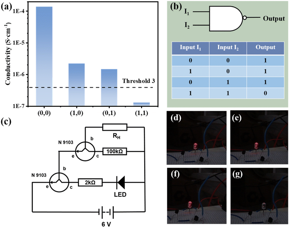
In order to achieve efficient optical logic circuits, the ON/OFF ratio is particularly important. Under the same illumination condition, different composite membranes have different ON/OFF ratios, as shown in Fig. 3(c). C2–1 has a ON/OFF ratio of 10.1 at 60 °C and 95% RH, which is higher than other types of composite membranes (the ratio of C0–0, C1–0, C1–1, C1–2 and C2–2 are 2.1, 3.7, 4.8, 2.8, 3.7, 8.5, respectively). Therefore, C2–1 was selected as the composite membrane to perform the optical-controlled logic gate, and was irradiated with 405 nm and 520 nm wavelength lasers. The intensity of the light has obvious effects on the SSP structural conformers. According to Fig. 3(d), it can be found that different light intensities have a great influence on the conductivity. At 50 °C and 95% RH, the conductivity of 405 nm laser irradiation with 400 mW cm−2 (σ = 6.97 × 10⁻⁷ S cm−1) is 7.7 times of that under the condition of 100 mW cm−2 (σ = 5.37 × 10⁻⁶ S cm−1). The electrical conductivity of 520 nm laser irradiated by 200 mW cm−2 (σ = 3.57 × 10⁻⁷ S cm−1) is ten times of that under 100 mW cm−2 (σ = 3.92 × 10⁻⁶ S cm−1), and has little change with that under 400 mW cm−2 (σ = 3.32 × 10⁻⁷ S cm−1). Therefore, a 405 nm laser of 400 mW cm−2 and a 520 nm laser of 200 mW cm−2 were selected as input light sources in the experimental conditions.
In Fig. 3(e), the conductivity switching ratio of C2–1 composite membrane at different temperatures at 95% RH is tested by using a 405 nm laser of 400 mW cm−2 and a 520 nm laser of 200 mW cm−2 as input light source. It can be found that the ON/OFF ratio reached 1067.7 at 55 °C. At 50 °C (137.0) and 60 °C (421.0), the ON/OFF ratio both decreased. According to Fig. S5(c) and (d),† at 55 °C and 95% RH, the proton conductivity in the dark (σ = 1.37 × 10⁻⁴ S cm−1) is 62 times higher than the conductivity with the 405 nm laser radiation (σ = 2.19 × 10⁻⁶ S cm−1) and 93 times higher the conductivity with the 520 nm laser radiation (σ = 1.47 × 10⁻⁶ S cm−1). When the 405 nm and 520 nm laser are on work together, the proton conductivity is 1.29 × 10⁻⁷ S cm−1. At the same time, the stability of the composite membrane was tested (showed in Fig. S5(f)†). During three cycles of 190 min, the conductivity of the composite membrane could still be transformed with different lighting conditions, basically maintaining the original ON/OFF ratio. It shows the stability of the composite membrane and the reversibility of the light induced conductivity change.
Fig. 3(f) illustrate the relationship between the logarithmic conductivity and temperature following Arrhenius-like behavior in the different optical control condition. In the dark state of C2–1, both Grotthuss mechanism and vehicle mechanism is followed in the proton transport, and the activation energy is greater than 0.4 eV, indicating that vehicle mechanism dominates.12 Since the temperature affect the vehicle mechanism with the adhesion of water molecules on the composite membrane and the Grotthuss mechanism by influencing the hopping activity of the proton. The temperature range in Fig. 3(f) is 45 °C to 60 °C, and the activation energy of C2–1 is relatively higher than the activation energy in Fig. S4(b)† (temperature range: 50 °C to 80 °C). With the increase of temperature, a small part of water molecules will escape, and block the vehicle mechanism which affects the proton transmission mechanism by H3O+ as the carrier in the membrane, resulting in a lower activation energy. Under the irradiation of 405 nm light source, the activation energy is 0.25 eV, which is due to the photothermal effect of Cu-TCPP. The sudden rise of temperature promotes the overflow of water molecules, greatly reduces the water molecular carrier, and destroys the original hydrogen bond network. The vehicle mechanism is more affected although both mechanisms are inhibited, resulting in that the activation energy decreases greatly. At 520 nm, light not only causes water molecules to overflow, but also converts SSP into MC form, further destroying hydrogen bond network. The photoinduced structural changes of SSP cause influence the Grotthuss mechanism. The activation energy (0.42 eV) decreased in a small amount under two proton transport mechanisms. When the two light sources were irradiated on the composite membrane at the same time, the activation energy is 0.23 eV under the combined action of photothermal effect and photoinduced structural changes.
Design and construction of multistate logic gates
As discussed above, humidity has significant effects on the protonic conductivity. The current generated by conductivity at 80% RH is not enough to construct a logic circuit. Hence, 95% RH was selected as the best RH for the experimentation. According to Fig. 3(e), 55 °C and 95% RH are selected as the realization conditions and C2–1 is chosen as the device for constructing the logic circuit with 405 nm laser of 400 mW cm−2 and 520 nm laser of 200 mW cm−2 as lighting conditions. According to the above research and analysis, some basic logic gate circuits are designed according to Boolean logic library. 405 nm and 520 nm lasers were used as the two input terms I1 and I2, and the light and dark of the LED were used as the output terms. The 1 and 0 of the input represent the presence and absence of the corresponding light source, respectively. And I1 and I2 are defined to describe the situation of the input end. 1 and 0 of the output are defined as light and dark, which are determined by the threshold value.If the value exceeds the threshold, status of LED is light and the output is 1. Otherwise, status of LED is dark and the output is 0. In the experiment, the threshold value can be controlled by simply changing the design of the circuit to achieve the effect of adjusting the brightness and darkness of the LED. The key to realize the function of logic circuit is the obvious change of conductivity before and after illumination, what is mean that the ON/OFF ratio has a larger value.
Fig. 4(a) and (b) shows the NOT gate design and its realization. As the most basic logic circuit, NOT gate realizes more complex circuits by combining with other basic logic gates. In the experiment, two resistors (100 kΩ and 47 kΩ), two transistors to amplify the current and one LED were used to form a circuit together (shown in Fig. 4(e)). I1 and I2 were used as inputs, and the threshold 1 of output is set to 4.0 × 10⁻⁶ S cm−1. In the dark, the conductivity of the composite membrane is large and the resistance is small, causes the LED lamp to glow red (Fig. 4(f)) and output is 1. In the illumination state, the resistance is large and the conductivity of the membrane is small, which makes the LED light dim (Fig. 4(i)) and output is 0.
 | ||
| Fig. 4 (a) Proton conductivity of C2–1 with I1 plus I2 as input with threshold 1 at 55 °C and 95% RH; (b) logic circuit symbols and truth table of NOT gate; (c) proton conductivity of C2–1 with I1 and I2 as input with threshold 2 at 55 °C and 95% RH; (d) logic circuit symbols and truth table of NOR gate; (e) schematic of the two-stage amplification circuit; RH represents the C2–1 composite membranes; N9013 is a transistor used to amplify current, where b is a base electrode, c is a collector electrode, e is a emitter electrode. The photographs of LED in the designed circuit under different lighting conditions: (f) in the dark; (g) with 520 nm light; (h) with 405 nm light; (i) with 520 nm and 405 nm light simultaneously. | ||
When only I1 or I2 is allowed to be input, the logic circuit may implement a NOR gate, a combination of a OR gate and a logic symbol for a NOT gate, as shown in Fig. 4(d). Similar to the NOT gate, the same circuit with the threshold 2 (σ = 2.0 × 10⁻⁵ S cm−1) is adopted. When both I1 and I2 are absent (input = (0, 0)), the LED will emit red light (output = 1). As shown in Fig. 4(f)–(i), when either laser or both are present (input = (1, 0), (0, 1), (1, 1)), the light is dimmed to go out (output = 0). The whole process is recorded in the Video S1.†
The composite membrane can also be realized with the design of NAND logic gates. As shown in Fig. 5(b) NAND gate is a combination of NO gate and AND gate. Modified on the basis of the previously designed line, different resistors (100 kΩ and 2 kΩ) are selected for the experiment, and NAND gate can be obtained, as shown in Fig. 5(c). At this time, the value of threshold 3 is 4.0 × 10⁻⁷ S cm−1. As shown in Fig. 5(d)–(g), when both I1 and I2 exist (input = (1, 1)), the LED light goes out (output = 0). When only one input item exists or none exists (input = (0, 0), (1, 0), (0, 1)), the LED light emits red light (output = 1). The whole process is recorded in the Video S2.†
 | ||
| Fig. 5 (a) Proton conductivity of C2–1 with I1 plus I2 as input with threshold 1 at 55 °C and 95% RH; (b) logic circuit symbols and truth table of NAND gate; (c) schematic of the two-stage amplification circuit. RH represents the C2–1 composite membranes. N9013 is a transistor used to amplify current, where b is a base electrode, c is a collector electrode, e is emitter electrode. The photographs of LED in the designed circuit under different lighting conditions; (d) without light; (e) with 520 nm light; (f) with 405 nm light; (g) with 520 nm and 405 nm light simultaneously. | ||
Conclusion
In summary, PSS and SSP were in situ co-incorporated into Cu-TCPP MOFs by solid-confinement method and resulting light-responsive proton-conducting membranes were prepared. The addition of PSS and SSP introduced sulfonic acid and phenolic groups, increasing the proton conductivity to 1.37 × 10⁻⁴ S cm−1 (at 55 °C and 95% RH). The device realizes the function of multistate logic gate through the photothermal effect of Cu-TCPP and the photoinduced structural changes of SSP. At 55 °C and 95% RH, 405 nm laser of 400 mW cm−2 and 520 nm laser of 200 mW cm−2 were used as inputs to make the conductivity of the device exist in multiple stable states, and the ON/OFF ratio is huge (1068). By adjusting the threshold, three kinds of basic logic gates (NOT gate, NOR gate, and NAND gate) can be constructed. The simple application of these three logic gates is realized through LED lights and current amplifying circuit with the light and dark state of LED. The simple light source provides convenience for the design of remote chemical sensors as the output, and the electrical signal as the output is easier to detect and directly carry out subsequent information transmission, which provides the possibility for the construction of complex logic gates.Author contributions
Kainan Xue: primary investigation, methodology, formal analysis and original draft writing and editing. Shabab Hussain: methodology, reviewing and editing. Shuaikang Fan: methodology. Xinsheng Peng: conceptualization, supervision, reviewing, resources, funding acquisition.Conflicts of interest
The authors declare no competing financial interest.Acknowledgements
This work was financially supported by the National Natural Science Foundation of China 218751212.Notes and references
- A. Fletcher, Anaesth. Intensive Care Med., 2019, 20, 243 CrossRef.
- L. B. Kier, R. Tombes, L. H. Hall and C. K. Cheng, Chem. Biodiversity, 2013, 10, 338 CrossRef CAS PubMed.
- O. D. Uchitel, C. G. Inchauspe and C. Weissmann, Synapse, 2019, 73, e22120 CrossRef PubMed.
- C. G. Inchauspe, F. J. Urbano, M. N. D. Guilmi and O. D. Uchitel, J. Neurosci., 2017, 37, 2589 CrossRef PubMed.
- M. J. Buch-Pedersen, B. P. Pedersen, B. Veierskov, P. Nissen and M. G. Palmgren, Pfluegers Arch., 2009, 457, 573 CrossRef CAS PubMed.
- L. B. Kier, Curr. Comput.-Aided Drug Des., 2021, 17, 333 CrossRef CAS PubMed.
- L. B. Kier and R. M. Tombes, Chem. Biodiversity, 2013, 10, 596 CrossRef CAS PubMed.
- G. M. Roozbahani, X. H. Chen, Y. W. Zhang and L. Wang, Small Methods, 2020, 4, 2000266 CrossRef CAS PubMed.
- K. Zhan, Z. Y. Li, J. Chen, Y. Q. Hou, J. Zhang, R. Q. Sun, Z. X. Bu, L. Y. Wang, M. Wang, X. Y. Chen and X. Hou, Nano Today, 2020, 33, 100868 CrossRef CAS.
- K. D. Kreuer, A. Rabenau and W. Weppner, Angew. Chem., Int. Ed. Engl., 1982, 21, 208 CrossRef.
- N. Agmon, Chem. Phys. Lett., 1995, 244, 456 CrossRef CAS.
- K. D. Kreuer, Chem. Mater., 1996, 8, 610 CrossRef CAS.
- W. H. Li, W. H. Deng, G. E. Wang and G. Xu, EnergyChem, 2020, 2, 100029 CrossRef.
- D. W. Lim and H. Kitagawa, Chem. Rev., 2020, 120, 8416 CrossRef CAS PubMed.
- Y. Ye, L. Gong, S. Xiang, Z. Zhang and B. Chen, Adv. Mater., 2020, 4, 1907090 CrossRef PubMed.
- L. Zhu, X. Q. Liu, H. L. Jiang and L. B. Sun, Chem. Rev., 2017, 117, 8129 CrossRef CAS.
- X. D. Wen, Q. Q. Zhang and J. Q. Guan, Coord. Chem. Rev., 2020, 409, 213214 CrossRef CAS.
- E. Adatoz, A. K. Avci and S. Keskin, Sep. Purif. Technol., 2015, 152, 207 CrossRef CAS.
- X. H. Ren, G. C. Liao, Z. J. Li, H. Qiao, Y. Zhang, X. Yu, B. Wang, H. Tan, L. Shi, X. Qi and H. Zhang, Coord. Chem. Rev., 2021, 435, 213781 CrossRef CAS.
- W. T. Dang, B. Ma, B. Li, Z. G. Huan, N. Ma, H. B. Zhu, J. Chang, Y. Xiao and C. T. Wu, Biofabrication, 2020, 12, 025005 CrossRef CAS PubMed.
- Y. Zhang and B. Yan, ACS Appl. Mater. Interfaces, 2019, 11, 20125 CrossRef CAS PubMed.
- J. M. Fang, P. F. Gao, X. L. Hu and Y. F. Li, RSC Adv., 2014, 4, 37349 RSC.
- J. Andréasson and U. Pischel, Chem. Soc. Rev., 2015, 44, 1053 RSC.
- X. Lian and B. Yan, ACS Appl. Mater. Interfaces, 2018, 10, 29779 CrossRef CAS PubMed.
- Y. Purusothaman, N. R. Alluri, A. Chandrasekhar, V. Venkateswaran and S. J. Kim, Nat. Commun., 2019, 10, 4381 CrossRef PubMed.
- X. N. Qi, Y. Q. Xie, Y. M. Zhang, H. Yao, Q. Lin and T. B. Wei, Sens. Actuators, B, 2021, 329, 129170 CrossRef CAS.
- S. K. Fan, S. L. Wang, X. B. Wang, X. Y. Wan, Z. Fang, X. P. Dong, Z. Z. Ye and X. Peng, Sci. China Mater., 2022, 65, 1076 CrossRef CAS.
- K. Müller, J. Helfferich, F. L. Zhao, R. Verma, A. B. Kanj, V. Meded, D. Bléger, W. Wenzel and L. Heinke M, Adv. Mater., 2018, 30, 1706551 CrossRef PubMed.
- F. Xiang, S. Chen, Z. Yuan, L. Li, Z. Fan, Z. Yao, C. Liu, S. Xiang and Z. Zhang, JACS Au, 2022, 6, 1043 CrossRef PubMed.
- H. Liang, Y. Guo, Y. Shi, X. Peng, B. Liang and B. Chen, Angew. Chem., Int. Ed., 2020, 59, 7732 CrossRef CAS PubMed.
- F. Xiang, S. Chen, S. Zheng, Y. Yang, J. He, Q. Lin, L. Wang, S. Xiang and Z. Zhang, ACS Appl. Mater. Interfaces, 2021, 9, 41363 CrossRef PubMed.
- S. Hussain, Z. Deng, A. Khan, P. P. Li, Z. Y. Li, Z. Fang, X. Y. Wan and X. Peng, J. Membr. Sci., 2021, 620, 118888 CrossRef CAS.
- M. Tian, F. Pei, M. S. Yao, Z. H. Fu, L. L. Lin, G. D. Wu, G. Xu, H. Kitagawa and X. L. Fang, Energy Storage Mater., 2019, 21, 14 CrossRef.
- G. Xu, K. Otsubo, T. Yamada, S. Sakaida and H. Kitagawa, J. Am. Chem. Soc., 2013, 135, 7438 CrossRef CAS PubMed.
- B. Li, X. Y. Wang, L. Chen, Y. L. Zhou, W. T. Dang, J. Chang and C. T. Wu, Theranostics, 2018, 8, 4086 CrossRef CAS PubMed.
- J. E. Cun, X. Fan, Q. Q. Pan, W. X. Gao, K. Luo, B. He and Y. J. Pu, Adv. Colloid Interface Sci., 2022, 305, 102686 CrossRef CAS PubMed.
- G. M. Geise, D. R. Paul and B. D. Freeman, Prog. Polym. Sci., 2014, 39, 1 CrossRef CAS.
- R. Klajn, Chem. Soc. Rev., 2014, 43, 148 RSC.
- E. A. Dolgopolova, V. A. Galitskiy, C. R. Martin, H. N. Gregory, B. J. Yarbrough, A. M. Rice, A. A. Berseneva, O. A. Ejegbavwo, K. S. Stephenson, P. Kittikhunnatham, S. G. Karakalos, M. D. Smith, A. B. Greytak, S. Garashchuk and N. B. Shustova, J. Am. Chem. Soc., 2019, 141, 5350 CrossRef CAS PubMed.
- Z. Y. Tian, W. W. Wu, W. Wan and A. D. Q. Li, J. Am. Chem. Soc., 2011, 133, 16092 CrossRef CAS PubMed.
- S. Garg, H. Schwartz, M. Kozlowska, A. B. Kanj, K. Müller, W. Wenzel, U. Ruschewitz and L. Heinke, Angew. Chem., Int. Ed., 2019, 58, 1193 CrossRef CAS PubMed.
- H. A. Schwartz and U. Ruschewitz, Struct. Bonding, 2020, 183, 105 CrossRef CAS.
- X. W. Xiong, M. S. Xiao, W. Lai, L. Li, C. H. Fan and H. Pei, Angew. Chem., Int. Ed., 2021, 60, 3397 CrossRef CAS PubMed.
- S. Kumar, J. T. V. Herpt, R. Y. N. Gengler, B. L. Feringa, P. Rudolf and R. C. Chiechi, J. Am. Chem. Soc., 2016, 138, 12519 CrossRef CAS PubMed.
Footnote |
| † Electronic supplementary information (ESI) available: Experimental details, SEM, EDX, zeta potential, XPS and UV-Vis-NIR data, Arrhenius plots, Nyquist plots and proton conductivity curve, etc. See DOI: https://doi.org/10.1039/d3ra01252b |
| This journal is © The Royal Society of Chemistry 2023 |