DOI:
10.1039/D3RA01118F
(Paper)
RSC Adv., 2023,
13, 16837-16849
Study on preparation and thermal properties of new inorganic eutectic binary composite phase change materials
Received
19th February 2023
, Accepted 2nd May 2023
First published on 5th June 2023
Abstract
It is important to improve phase change materials (PCMs) with appropriate temperature and excessive latent heat to accelerate the application of latent heat energy storage technology in solar energy storage systems. In this paper, the eutectic salt of NH4Al(SO4)2·12H2O (AASD) and MgSO4·7H2O (MSH) was prepared and the performance was studied. The DSC results show that the optimum content of AASD in the binary eutectic salt is 55 wt%, the melting point was 76.4 °C, and the latent heat is up to 189.4 J g−1, which is suitable for solar power storage systems. Four nucleating agents (KAl(SO4)2·12H2O, MgCl2·6H2O, CaCl2·2H2O, CaF2) and two thickening agents (sodium alginate, soluble starch) are added to the mixture in varying proportions to improve its supercooling. The best combination system was 2.0 wt% KAl(SO4)2·12H2O/1.0 wt% sodium alginate with a supercooling degree of 24.3 °C. After thermal cycling tests, the best formulation of the AASD–MSH eutectic salt phase change material was determined to be 1.0 wt% CaCl2·2H2O/1.0 wt% soluble starch. The latent heat was 176.4 J g−1 and the melting point was 76.3 °C. The supercooling was still lower than 30 °C after 50 thermal cycles, which served as a benchmark for the next investigation.
1. Introduction
Energy storage technology can temporarily store energy for rational distribution, which is an important way to achieve the dual-carbon goal.1 In the process of converting and utilizing energy, there are frequently inconsistencies between supply and demand for energy in time and space distribution, for example the difference in the power grid's peak-valley load,2 the intermittence and volatility of the solar energy distribution over time,3 the waste heat of the power plant across time and space utilization,4 etc. Energy storage technologies can play a key role. One of the most promising energy storage technologies among the several energy storage options is thermal energy storage.5 Technologies for storing thermal energy can be categorized into three groups: thermochemical energy storage, phase change energy storage, and sensible thermal energy storage. Sensible thermal energy storage has a poor heat storage density. Thermochemical energy storage has a far higher energy storage density than the other two types of energy storage, but it has several practical application restrictions because of the complexity of its system design and upkeep. However, the energy storage density of phase change energy storage is larger than that of sensible heat storage because it constantly releases or absorb a large amount of latent heat at a steady temperature during the phase change process. Moreover, PCMs have higher adaptability to the system than thermochemical energy storage materials.6 As an important part of phase change energy storage materials, inorganic hydrated salts have a wide range of applications in heat storage.7–9 Compared with organic PCMs, inorganic hydrated salts are less costly, higher heat storage density and higher thermal conductivity than it,10 so they are frequently utilized for thermal management, such as building energy conservation,11 industrial waste heat utilization,12 solar energy storage13 and other fields for large-scale use. The application temperature zone of most hydrated salt phase change heat storage overlaps with the sensible heat storage temperature zone of traditional water. While hydrated salt has higher heat storage density and better comprehensive performance in the range of medium and low temperature (70–100 °C). However, issues like phase separation and supercooling affect inorganic hydrated salts. Currently, the cold finger approach is frequently used by researchers to address the issue of supercooling,14 microcapsule encapsulation,15 adding nucleating agent16 and other methods. Although cold fingering improves the supercooling phenomenon obviously, it will reduce the heat storage capacity. Microcapsule fragile, coating rate is not high, latent heat value is low, weak mechanical properties; the most efficient and cost-effective technique to address this issue is to use nucleating agents, which can significantly decrease the supercooling of hydrated salt phase change thermal storage materials by adding suitable nucleating agents to provide nucleation sites for the solution. Researchers have vigorously promoted the study of different hydrated salt nucleating agents. Zhang et al.17 found that Na4P2O7·10H2O (TSPP) as a nucleating agent significantly decreased the supercooling of Na2S2O3·5H2O. When mixed with 0.08% Na4P2O7·10H2O (TSPP) nucleating agent and 2% sodium polyacrylate (PAAS) thickener, the phase change material has good cycling stability and can be subcooled to 3.6 °C. Putri et al.18 selected 12 nucleating agents, by adding 1 wt% of each nucleating agent to the solution, the enhancement impact of each nucleating agent on the supercooling of Ca(NO3)2·4H2O was ascertained. The findings demonstrated that BaCO3 was the most effective and appropriate nucleating agent for Ca(NO3)2·4H2O. The average supercooling degree decreased to 1.45 °C. At present, to solve the problem of phase separation, researchers often use mechanical stirring,19 adding excessive water,20 adding thickening agent21 and other methods. Mechanical stirring method makes the precipitated inorganic salts evenly distributed into the crystalline water by physical agitation, but its operation method is too complicated. The addition of excessive water can prevent the formation of saturated solution after the melting of hydrated salts, thus preventing the occurrence of phase separation at the source, but this method will increase the heat loss of PCM,22 thus reducing its application value. Thickener method is the most effective and economical measure to solve this problem by adding the right amount of thickener to prevent the aggregation and settlement of inorganic salts due to the density difference, so that the water is evenly distributed and the contact area between inorganic salts and water is maximized as much as possible during solidification. By adding thickening agent, such as disodium hydrogen phosphate dodecahydrate,23 hydroxyethyl cellulose (HEC)24–26 and carboxymethylcellulose sodium (CMC),27–29 it can successfully resolve the issue of hydrated salts' phase separation, and improve the nucleating agent's dispersion in hydrated salts. Thus, the subcooling is further reduced. Compared with elemental hydrated salts, eutectic salts can promote crystallization of each other, improve phase separation and supercooling. In some eutectic salt systems, in addition to facilitating phase separation and lowering supercooling, it also can control the melting point of hydrated salts. Xie et al.30 studied a binary eutectic mixture of oxalic acid dihydrate/boric acid (OCD–BA) containing 88 wt% oxalic acid dihydrate and 12 wt% boric acid, additionally established was the binary system's solid–liquid phase diagram. The outcomes demonstrated that mixture of the two hydrated salts reduced the melting point while retaining the majority of the melting enthalpy.
When PCMs is used in low-temperature fields such as solar domestic hot water systems and solar collectors, the melting temperature requirement is 40–80 °C.31 The hydrated salts in the medium and low temperature range are mainly barium hydroxide octahydrate (Tm: 78 °C),32 magnesium nitrate hexahydrate (Tm: 89 °C),33 ammonium aluminium sulphate dodecahydrate (Tm: 93.5 °C),34 magnesium sulphate heptahydrate (Tm: 95.4 °C), etc. But barium hydroxide octahydrate has very high toxicity,32 magnesium nitrate hexahydrate has low latent heat, and the supercooling situation is very serious.35 Ammonium aluminium sulphate dodecahydrate (NH4Al(SO4)2·12H2O) is an non-toxic and low price inorganic hydrated salt with excellent heat storage performance. It has a latent heat of 269 J g−1, a melting point of 93.5 °C, a high thermal conductivity of 0.55 W (m−1 K−1), and a small volume change of 7%.36,37 As a kind of congruent melting PCM, there is no phase separation during repeated cooling and solidification. However, there are serious supercooling problems in the application.12,38,39 Additionally, because of its melting temperature being so close to the temperature at which water evaporates, it is easy for crystalline water to evaporate during the cycling process, which leads to poor stability and reusability and restricts the use of phase change energy storage,40 to our knowledge, very few studies have looked into eutectic mixtures made of NH4Al(SO4)2·12H2O. Sun et al.41 studied the phase transition properties of NH4Al(SO4)2·12H2O–MgCl2·6H2O and KAl(SO4)2·12H2O–MgCl2·6H2O mixtures. According to the results of DSC analysis, the optimum content of magnesium chloride in the two mixed salts was determined to be 30 wt%. The melting points were 64.15 °C and 60.15 °C, and the latent heat of phase change was 192.1 J g−1 and 198.1 J g−1, respectively. However, due to its comparatively low melting point, there is a problem of insufficient sensible heat storage in solar energy applications. Magnesium sulphate heptahydrate (MgSO4·7H2O) is easily soluble in water, and the aqueous solution is less corrosive. It is a by-product of salt processing and has the advantages of low cost and easy availability.42 However, MgSO4·7H2O has a very serious phase separation in application. The eutectic salt formed by mixing the two can reduce its melting point, MgSO4·7H2O can reduce the supercooling degree of NH4Al(SO4)2·12H2O, while NH4Al(SO4)2·12H2O can alleviate the serious phase separation of MgSO4·7H2O, therefore, we choose to mix NH4Al(SO4)2·12H2O and MgSO4·7H2O to obtain a new binary eutectic salt phase change material with suitable melting point, low supercooling degree, no phase separation, excellent thermal performance and low cost. From the reviewed papers, many eutectic PCMs are currently developed for different applications, but only a few inorganic eutectic salt PCMs have been found in the temperature range of 60–80 °C. As shown in Table 1, the eutectic salt in this paper has a suitable phase transition temperature as well as a higher phase transition enthalpy compared to other eutectic salts in the literature, which reflects its novelty and can be applied in latent heat storage systems.
Table 1 Eutectic salt hydrates used as PCM
| Eutectic salt hydrate composition |
Melting point (°C) |
Latent heat (J g−1) |
Reference |
| 53% Mg(NO3)2·6H2O + 47% Al(NO3)2·9H2O |
61 |
148 |
43 |
| 80% Mg(NO3)2·6H2O + 20% MgCl2·6H2O |
60 |
150 |
44 |
| 41.3% MgCl2·6H2O + 58.7% Mg(NO3)2·6H2O |
61.4 |
127.45 |
45 |
| 15% MgCl2·6H2O + 85% Mg(NO3)2·6H2O |
70 |
142.8 |
46 |
| 10% Ca(NO3)2·4H2O + 90% Mg(NO3)2·6H2O |
70 |
145 |
46 |
| 40% MgCl2·6H2O + 60% Mg(NO3)2·6H2O |
62 |
132.5 |
47 |
| 55% NH4Al(SO4)2·12H2O + 45% MgSO4·7H2O |
76.4 |
189.4 |
Present study |
In the current work, a binary hydrated salt phase change material was explored, which combines ammonium aluminium sulphate dodecahydrate (NH4Al(SO4)2·12H2O) magnesium and sulphate heptahydrate (MgSO4·7H2O) by melt blending. Two hydrated salts with various mass fractions were tested for their characteristics in order to ascertain the composition of eutectic salts. Four nucleating agents and two thickening agents were added to further reduce the supercooling degree of the eutectic salt. In this study, a novel eutectic salt PCM with low supercooling, no phase separation, excellent thermal performance, suitable melting point and low cost was prepared by a simple melt blending method, which is suitable for solar thermal storage or waste heat recovery. The research results have certain guiding significance for the design and construction of latent heat storage system of PCMs.
2. Materials and methods
2.1 Materials and reagents
Aluminium ammonium sulphate dodecahydrate (NH4Al(SO4)2·12H2O, AASD), magnesium sulphate heptahydrate (MgSO4·7H2O, MSH) was purchased from Shanghai Macklin Biochemical Co. Ltd. (Shanghai, China). The parameters of the four nucleating agents and two thickening agents and the crystal parameters of the thickening agents are shown in Tables 2 and 3, respectively.
Table 2 Material details
| Material |
Abbreviation |
Chemical formula |
Function |
Manufacturer |
| Aluminum potassium sulfate dodecahydrate |
APSD |
KAl(SO4)2·12H2O |
Nucleating agent |
Shanghai Macklin Biochemical Co. Ltd |
| Magnesium chloride hexahydrate |
MCH |
MgCl2·6H2O |
Nucleating agent |
Kemio Chemical Reagent Co., Ltd |
| Calcium chloride dihydrate |
CCD |
CaCl2·2H2O |
Nucleating agent |
Kemio Chemical Reagent Co., Ltd |
| Calcium fluoride |
CF |
CaF2 |
Nucleating agent |
Shanghai Macklin Biochemical Co. Ltd |
| Sodium alginate |
SA |
C6H7NaO6 |
Thickening agent |
Shanghai Macklin Biochemical Co. Ltd |
| Soluble starch |
SS |
C12H22O11 |
Thickening agent |
Kemio Chemical Reagent Co., Ltd |
Table 3 Crystal parameters
| Substance |
Crystal form |
a (Å) |
b (Å) |
c (Å) |
α (deg) |
β (deg) |
γ (deg) |
| APSD |
Cubic system |
12.18 |
12.18 |
12.18 |
90.0 |
90.0 |
90.0 |
| MCH |
Monoclinic system |
9.87 |
7.11 |
6.08 |
90.0 |
93.7 |
90.0 |
| CCD |
Tetragonal system |
7.21 |
7.21 |
5.86 |
90.0 |
90.0 |
90.0 |
| CF |
Cubic system |
5.46 |
5.46 |
5.46 |
90.0 |
90.0 |
90.0 |
2.2 Sample preparation
2.2.1 Preparation of AASD–MSH mixtures. A series of AASD–MSH mixtures with different mass fractions of AASD (90 wt% to 10 wt%) were prepared to determine the optimal proportion of AASD and MSH. The steps of the experiment are as follows: a reagent bottle was filled with AASD and MSH after they had been weighed. The two hydrated salts were briefly stirred before being heated to 100 °C in an oven and held there for 3 h. The two hydrated salts were then heated while being stirred intermittently to ensure thorough mixing. The AASD–MSH mixture was then obtained by cooling the solution to room temperature.
2.2.2 Preparation of composite phase change materials (CPCMs). The mixture was heated to 90 °C in a water bath and magnetic stirring for 1 h simultaneously. After melting, 40 kinds of CPCMs were prepared by mixture with 0.5, 1, 1.5, 2 wt% nucleating agent (KAl(SO4)2·12H2O, MgCl2·6H2O, CaCl2·2H2O, CaF2) and 0.5, 1, 1.5 wt% thickening agent (sodium alginate, soluble starch) magnetic stirring at 90 °C for 15 min, which can be seen from Tables 6–9 (the total mass of CPCMs samples was controlled at 20 g). The optimum mass fraction of the four nucleating agents and two thickening agents were obtained by the investigation of step cooling curve.
2.3 Characterization
The phase transition temperature and latent heat of the specimens were quantified using a Differential Scanning Calorimeter (DSC, Model Q100, manufactured in the United States). To ensure accurate DSC measurements, the mass of each specimen was kept within the range of 5 to 8 mg. The instrument was calibrated using a blank aluminium pan prior to analysis. Each specimen was enclosed within an aluminium pan and subjected to a controlled heating process, with a temperature increase from 30 °C to 140 °C at a rate of 5 °C per minute, while being subjected to a constant nitrogen flow of 50 mg per minute.
The structural characterization of AASD, MSH, and their mixture was performed using Fourier Transform Infrared Spectroscopy (FT-IR) and X-ray Diffraction (XRD) techniques. The FT-IR spectra were recorded using a Vertex70 spectrometer over a spectral range of 500 to 4000 cm−1. XRD patterns of the samples were acquired using a D8 ADVANCE X-ray diffractometer, with a measurement range of 5° to 80°. The thermal conductivity of the samples was measured utilizing a LFA 467 Thermal Constants Analyzer manufactured by Germany.
2.4 Measurement of cooling curves
In this study, crystallization properties of the mixed samples were characterized by measuring the cooling curve. Place the sample in a 50 ml sealed glass bottle and a k-type thermocouple is placed in the centre of the glass bottle to monitor the temperature change of each sample, and the measurement error is ±0.1 °C. In addition, the temperature measuring points in different tests are located at the same depth (10 mm from the bottom of the glass bottle) to ensure that the input heat flux from the top to bottom have the same effect on them. During the measurement, the sealed glass bottle is placed in a thermostatic water bath at 90 °C for 2 h until the sample is completely melted. Constant temperature water bath can freely control the temperature accuracy with ±0.01 °C. Then, take the sealed glass bottle out of the thermostatic water bath and cool to the room temperature. The temperature change of the sample during the whole process was recorded by a data acquisition instrument (Agilent 34970A, Santa Clara, CA, USA).
2.5 Theoretical determination of AASD–MSH eutectic salt
The molar ratios of each substance of binary eutectic salt were evaluated using the Schroder–van Laar equation.| |
 | (1) |
where Xk is the molar ratio of the k-component, ΔHkm is the melting enthalpy in J mol−1, T and Tkm are melting temperatures of components in kelvin and R is the universal gas constant in 8.31 J (mol−1 K−1).
3. Results and discussion
3.1 Determining the optimal mixture composition
In order to determine the mass fraction of eutectic point, the thermal physical properties of mixtures with different AASD are obtained by camera photography and DSC. As shown in Fig. 1, the solution gradually changes from clear to turbid with the decrease of mass fraction of AASD. When the mass fraction of AASD are 20 wt% and 10 wt%, respectively, there is a very obvious phase separation at the bottom of the solution. This is due to the fact that the MSH content is too high to have a serious phase separation, and the salt cannot be dissolved in the precipitated crystal water after reaching the phase change temperature. Therefore, the two samples of AASD with mass ratio of 20 wt% and 10 wt% are directly not considered. Fig. 2a shows the DSC curves of the pure AASD and MSH. The latent heat of AASD is 296.5 J g−1, and the phase change temperature is 93.3 °C. There are three endothermic peaks in the DSC curves of MSH. The latent heat of MSH is 202.6 J g−1, and the phase change temperature is 95.4 °C. Fig. 2b is the DSC curves of AASD–MSH mixture containing different mass fractions of AASD. It can be seen from the diagram that with the decrease of the content of AASD, the DSC curve mainly shows two peaks, one large and one small. The first endothermic peak is mainly located at about 55 °C, which is basically the same as the first endothermic peak position of MSH. The second peak is mainly located at 75 °C to 95 °C, which should be the result of the interaction between the endothermic peak of AASD and the second and third endothermic peaks of MSH. The second endothermic peak of the mixture exhibits two broad peaks which are slowly approaching with the increase of mass fraction of MSH, indicating that the mixture at this ratio is close to the eutectic point of the two hydrous salt.48 When the mass fraction of AASD is 60 wt%, the two peaks change into a single main peak. When the mass fraction of AASD is 50 wt%, the DSC curve shows a sharp single peak, indicating that the eutectic point of the mixture is near this ratio.
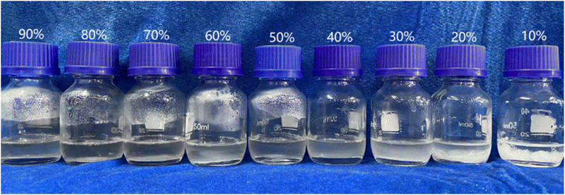 |
| | Fig. 1 Photographs of mixtures with different mass fraction of AASD (90 wt% to 10 wt%). | |
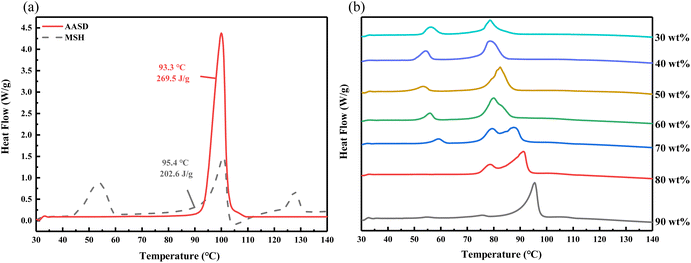 |
| | Fig. 2 DSC curves of the pure AASD and MSH (a) and mixtures with different mass fraction of AASD (b). | |
In order to obtain the exact mass ratio of the two hydrated salts, Fig. 3 shows the DSC curves with an interval of 5 wt% near the AASD content of 50 wt% and 60 wt%. It can be seen that when the mass fraction of AASD decreased to 55 wt%, the main peak of the mixed hydrated salt changes from a weak broad peak to a single peak, which indicating the formation of the eutectic salt. There is a single peak of the mixture with 50 wt% AASD, but the degree of the sharpness is weaker. Therefore, the eutectic salt with 55 wt% AASD was selected as the optimal mass ratio.
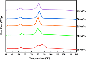 |
| | Fig. 3 DSC curves of mixtures with different mass fraction of AASD (65 wt% to 45 wt%). | |
From the theoretical calculation of eqn (1), the mass ratio of AASD and MSH can be obtained as 57.09 wt%:42.91 wt%. It is very close to the experimental results, which proves the scientific validity of the experiment. The eutectic salt mentioned below are of this proportion.
Table 4 shows the phase transition temperature and latent heat of six samples of mixed salts with different contents. It can be seen that due to the mixing of two hydrated salts, the phase transition temperature is lower than that of the individual hydrated salt, and is much lower than the boiling temperature of water, which can effectively avoid the evaporation of crystal water in the eutectic salt. The latent heat of phase transition decreases with the decrease of AASD content, but it is still as high as 189.4 J g−1. In summary, AASD–MSH eutectic salt has the advantages of suitable phase transition temperature and high latent heat. It has the possibility of application in the field of solar thermal storage.
Table 4 Thermal characteristics of mixtures with different mass fractions of AASD
| FAASD (wt%) |
Tmelt (°C) |
ΔH (J g−1) |
| 65 |
Two peaks |
212.0 |
| 60 |
75.6 |
189.3 |
| 55 |
76.4 |
189.4 |
| 50 |
78.9 |
191.0 |
| 45 |
78.2 |
178.3 |
| 40 |
75.4 |
178.5 |
3.2 Structure of the eutectic salt
XRD and FT-IR patterns of AASD, MSH and the eutectic salt were attached in Fig. 4. As shown in Fig. 4a, it can be seen that the main characteristic peaks of AASD appear at 12.7°, 16.4°, 20.7° and 27.4°, and the main characteristic peaks of MSH appear at 20.4°, 21.2°, 23.6° and 43.0°. The characteristic peaks of AASD and MSH appear in the eutectic salt. At the same time, several smaller new characteristic peaks appear in the eutectic salt XRD pattern, which may be due to the aggregation crystals formed by the mixing of AASD and MSH.
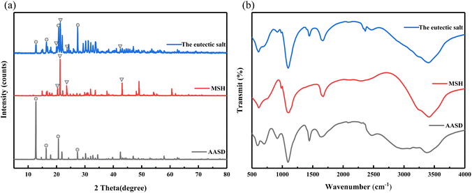 |
| | Fig. 4 XRD (a) and FT-IR patterns (b) of AASD, MSH and the eutectic salt. | |
Fig. 4b presents the FT-IR spectra of AASD, MSH, and the eutectic salt. The spectra of AASD and MSH exhibit the H–O–H stretching vibration peaks at 3362 and 2950 cm−1 and bending vibration peaks at 1625 cm−1. A characteristic O–H stretching vibration peak appears at 2460 cm−1. The peak observed at 1105 cm−1 is attributed to the asymmetric stretching of SO42−, and the peak at 595 cm−1 corresponds to the asymmetric deformation absorption of SO42−. Furthermore, AASD and MSH exhibit an asymmetric deformation absorption peak of NH4+ at 1441 cm−1. In the FT-IR spectra of the eutectic salt, all the peaks correspond to those of AASD and MSH, with no additional peaks being formed, which suggests that AASD and MSH have good compatibility and that their mixing is only a simple physical process, devoid of any chemical reactions.
3.3 Thermal reliability of the eutectic salt
Fig. 5 is the DSC curve of the eutectic salt after 100 heating and cooling cycles. It can be seen from Fig. 5 that the phase transition temperature of the eutectic salt changed from 76.4 °C to 76.3 °C after 100 cycles of heating and cooling, while the latent heat of phase transition decreased from 189.4 J g−1 to 181.3 J g−1, with only 4.28% loss. These phase change characteristics show that the phase transition characteristics of the eutectic salt have little change before and after the cycles. In addition, there was no obvious precipitation at the bottom of the glass bottle after 100 cycles of the eutectic salt. All the results illustrated that the eutectic salt have high thermal reliability.
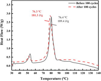 |
| | Fig. 5 DSC result of the eutectic salt before and after tests. | |
3.4 Study on subcooling characteristics of the eutectic salt
As AASD has high supercooling degree, MSH was added to form eutectic salt to accelerate its nucleation rate and then decrease the supercooling degree. Fig. 6 is the step cooling curve of AASD, MSH and the eutectic salt. Table 5 is the melting crystallization and supercooling temperature of AASD, MSH and the eutectic salt. As shown in Fig. 6, the blue dotted line is the melting temperature of the eutectic salt obtained from the DSC curve, ΔTm is the melting temperatures of the eutectic salt, and the melting temperatures of AASD and MSH are 93.3 °C and 95.4 °C, respectively, which can be seen from Fig. 3. ΔTs is the supercooling degree of AASD, this supercooling criterion is used below. It can be seen that AASD, MSH and the eutectic salt have serious supercooling degree. Through the mixing of two hydrated salts, the problem of excessive supercooling degree of single AASD has been slightly improved. Fig. 6 provides a comprehensive analysis of the characteristics of the eutectic salt, including: (1) a supercooling degree of 34.9 °C; (2) a maximum crystallization temperature of 48.9 °C, which is 27.5 °C lower than its melting point; (3) no discernible phase transition platform during the exothermic process. These characteristics (1), (2), and (3) of the eutectic salt are a result of a low nucleation rate, low crystal growth rate, and imbalanced exothermic and solidification latent heat.49 In order to address the issue of low nucleation rate and high supercooling degree in the eutectic salt, nucleating agents and thickening agents were introduced as solutions.
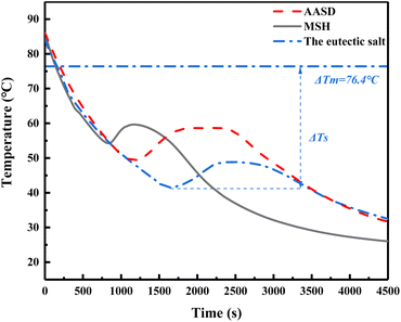 |
| | Fig. 6 Step cooling curves of AASD, MSH and the eutectic salt. | |
Table 5 Melting/crystallization temperature and supercooling degree of AASD, MSH and the eutectic salt
| Hydrated salts |
Tmelt (°C) |
Tmin-crystal (°C) |
Tmax-crystal (°C) |
Supercooling (ΔT/K) |
| AASD |
93.3 |
49.4 |
58.6 |
43.9 |
| MSH |
95.4 |
54.3 |
59.7 |
41.1 |
| The eutectic salt |
76.4 |
41.5 |
48.9 |
34.9 |
Table 6 Supercooling degree of adding different proportions of APSD, SA and SS
| Sample |
FAPSD (wt%) |
Thickening agent |
Supercooling (ΔT/K) |
| 1 |
0.5 |
1.0 wt% SA |
31.5 |
| 2 |
1.0 |
1.0 wt% SA |
27.8 |
| 3 |
1.5 |
1.0 wt% SA |
27.6 |
| 4 |
2.0 |
1.0 wt% SA |
24.3 |
| 5 |
0.5 |
1.0 wt% SS |
27.7 |
| 6 |
1.0 |
1.0 wt% SS |
28.1 |
| 7 |
1.5 |
1.0 wt% SS |
28.0 |
| 8 |
2.0 |
1.0 wt% SS |
28.7 |
| 9 |
2.0 |
0.5 wt% SA |
27.9 |
| 10 |
2.0 |
1.5 wt% SA |
30.6 |
Table 7 Supercooling degree of adding different proportions of MCH, SA and SS
| Sample |
FMCH (wt%) |
Thickening agent |
Supercooling (ΔT/K) |
| 11 |
0.5 |
1.0 wt% SA |
30.4 |
| 12 |
1.0 |
1.0 wt% SA |
30.6 |
| 13 |
1.5 |
1.0 wt% SA |
29.4 |
| 14 |
2.0 |
1.0 wt% SA |
33.8 |
| 15 |
0.5 |
1.0 wt% SS |
32.6 |
| 16 |
1.0 |
1.0 wt% SS |
30.3 |
| 17 |
1.5 |
1.0 wt% SS |
31.0 |
| 18 |
2.0 |
1.0 wt% SS |
33.0 |
| 19 |
1.5 |
0.5 wt% SA |
31.4 |
| 20 |
1.5 |
1.5 wt% SA |
29.6 |
Table 8 Supercooling degree of adding different proportions of CCD, SA and SS
| Sample |
FCCD (wt%) |
Thickening agent |
Supercooling (ΔT/K) |
| 21 |
0.5 |
1.0 wt% SA |
30.4 |
| 22 |
1.0 |
1.0 wt% SA |
31.0 |
| 23 |
1.5 |
1.0 wt% SA |
31.9 |
| 24 |
2.0 |
1.0 wt% SA |
33.0 |
| 25 |
0.5 |
1.0 wt% SS |
28.1 |
| 26 |
1.0 |
1.0 wt% SS |
28.0 |
| 27 |
1.5 |
1.0 wt% SS |
29.7 |
| 28 |
2.0 |
1.0 wt% SS |
30.9 |
| 29 |
1.0 |
0.5 wt% SS |
31.9 |
| 30 |
1.0 |
1.5 wt% SS |
32.6 |
3.4.1 Effect of APSD on the supercooling degree of the eutectic salt. To study the effect of APSD and two thickening agents on the heat storage/release performance of the eutectic salt, Fig. 7 shows the step cooling curves of the eutectic salt with 0.5 wt%, 1 wt%, 1.5 wt%, 2 wt% nucleating agent APSD and 0.5 wt%, 1 wt%, 1.5 wt% thickening agent SA and SS. It can be seen from Fig. 7a that with 1 wt% SA, the supercooling degree of the eutectic salt gradually decreases with the increase of APSD content. The addition of 2 wt% nucleating agent APSD has the best improvement effect, and the supercooling degree is reduced to 24.3 °C. As can be seen from Fig. 7b, with 1 wt% SS, the supercooling degree of the eutectic salt is lower than that of the pure eutectic salt, but with the increase of APSD content, the supercooling degree is always about 28 °C. The effect of APSD–SS is not as good as that of APSD–SA. It can be seen from Fig. 7d that after the content of APSD was determined to be 2 wt%, the content of SA was used as a variable. When the content of SA was 0.5 wt%, the degree of supercooling was higher than that when the content of SA was 1 wt%. When the amount of thickening agent was too small, the thickening suspension effect was not obvious, resulting in the deposition of APSD at the bottom, which could not fully act as a nucleating agent. When the content of SA increased to 2 wt%, too much thickening reduced the crystallization temperature, and the degree of supercooling was too large.
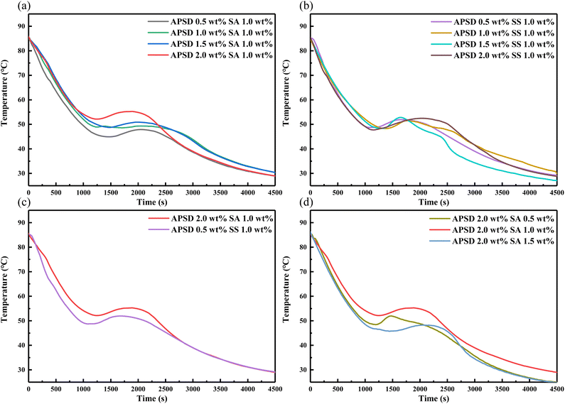 |
| | Fig. 7 Step cooling curves of the eutectic salt with 0.5, 1, 1.5, 2 wt% APSD and 0.5, 1, 1.5 wt% thickening agent (SA and SS). | |
3.4.2 Effect of MCH on the supercooling degree of the eutectic salt. To study the effect of MCH and two thickening agents on the heat storage/release performance of the eutectic salt, Fig. 8 shows the cooling curves of the eutectic salt with 0.5 wt%, 1 wt%, 1.5 wt%, 2 wt% nucleating agent MCH and 0.5 wt%, 1 wt%, 1.5 wt% thickening agent SA and SS. According to the previous steps, with the ratio of MCH as the variable, with the same content of 1 wt% SA and SS, it can be seen that the supercooling degree of the eutectic salt reaches the lowest when the content of MCH is 1.5 wt% and 1.0 wt%, respectively. Although different thickening agents are used, with the gradual increase of MCH content, the content of thickening agent is small, which leads to insufficient suspension of nucleating agent, resulting in its accumulation at the bottom of the container, and the supercooling degree decreases first and then increases. After determining the type of thickening agent and the content of nucleating agent, the content of SA was used as a variable. When the content of thickening agent was increased to 1.5 wt%, the improvement of supercooling degree was not obvious. After comprehensive comparison, 1.5 wt% nucleating agent MCH and 1% thickening agent SA had the best improvement of supercooling degree, and the supercooling degree was 29.4 °C.
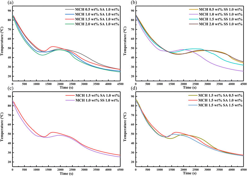 |
| | Fig. 8 Heat release curves of the eutectic salt with 0.5, 1, 1.5, 2 wt% MCH and 0.5, 1, 1.5 wt% thickening agent (SA and SS). | |
3.4.3 Effect of CCD on the supercooling degree of the eutectic salt. To study the effect of CCD and two thickening agents on the heat storage/release performance of the eutectic salt, Fig. 9 shows the cooling curves of the eutectic salt with 0.5 wt%, 1 wt%, 1.5 wt%, 2 wt% nucleating agent CCD and 0.5 wt%, 1 wt%, 1.5 wt% thickening agent SA and SS. According to the previous steps, the ratio of CCD was used as a variable, with the same content of 1 wt% SA and SS. When the content of CCD was 0.5 wt%, the SA was the best, and the supercooling degree was the smallest. With the increase of nucleating agent content, there was also a reason for insufficient suspension strength. When mixed with SS, the optimum addition ratio of CCD was 1.0 wt%, and there was an obvious phase change platform. After determining the content of nucleating agent, with the addition ratio of soluble starch as a variable, it can be seen that the effect of coordination with the other two nucleating agents is not good. The best ratio is 1.0 wt% CCD and 1.0 wt% SS, and the supercooling degree is 28.0 °C.
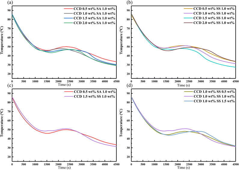 |
| | Fig. 9 Heat release curves of the eutectic salt with 0.5, 1, 1.5, 2 wt% CCD and 0.5, 1, 1.5 wt% thickening agent (SA and SS). | |
3.4.4 Effect of CF on the supercooling degree of the eutectic salt. To study the effect of MCH and two thickening agents on the heat storage/release performance of the eutectic salt, Fig. 10 shows the cooling curves of the eutectic salt with 0.5 wt%, 1 wt%, 1.5 wt%, 2 wt% nucleating agent CF and 0.5 wt%, 1 wt%, 1.5 wt% thickening agent SA and SS. Combined with Table 9, we can see that in the combination of different proportions of CF and SS, the best combination to improve the supercooling degree is 2.0 wt% CCF and 1.0 wt% SA, and the supercooling degree is 26.7 °C. In the combination with SS, the best combination to improve the supercooling degree is 2.0 wt% CF and 1.0 wt% SS, and the supercooling degree is 24.5 °C. Both of them have obvious phase transition platform. After changing the variable into SS ratio, the comprehensive effect of 0.5 wt% and 1.5 wt% SS and CF is not obvious. Therefore, it can be determined that 2.0 wt% CF and 1.0 wt% SS are the best ratio.
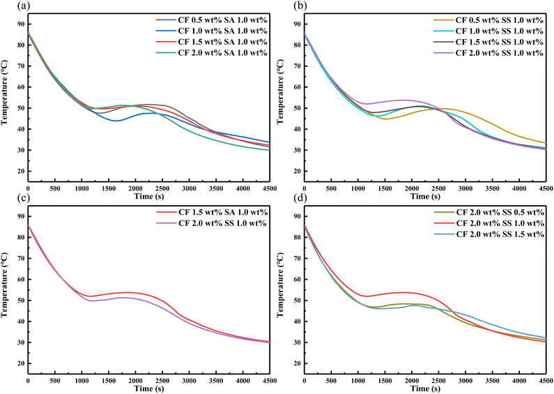 |
| | Fig. 10 Heat release curves of the eutectic salt with 0.5, 1, 1.5, 2 wt% CF and 0.5, 1, 1.5 wt% thickening agent (SA and SS). | |
Table 9 Supercooling degree of adding different proportions of CF, SA and SS
| Sample |
FCF (wt%) |
Thickening agent |
Supercooling (ΔT/K) |
| 31 |
0.5 |
1.0 wt% SA |
28.7 |
| 32 |
1.0 |
1.0 wt% SA |
32.5 |
| 33 |
1.5 |
1.0 wt% SA |
26.7 |
| 34 |
2.0 |
1.0 wt% SA |
26.7 |
| 35 |
0.5 |
1.0 wt% SS |
31.6 |
| 36 |
1.0 |
1.0 wt% SS |
30.2 |
| 37 |
1.5 |
1.0 wt% SS |
28.5 |
| 38 |
2.0 |
1.0 wt% SS |
24.5 |
| 39 |
2.0 |
0.5 wt% SS |
29.6 |
| 40 |
2.0 |
1.5 wt% SS |
30.3 |
3.5 Phase change characteristics and thermal conductivity of CPCMs
The DSC curves of the four CPCMs are shown in Fig. 11, and the corresponding parameter values are shown in Table 10. The phase transition temperatures of the four CPCMs are close to those of the mixed salt without any substance added. The latent heat of the four CPCMs are lower than the eutectic salt. This is because the nucleating agent and the thickening agent do not undergo phase transition at this temperature range. The addition of these substances will cause the loss of unit latent heat. However, the latent heat of the four CPCMs are higher than 165 J g−1, and there is still an advantage compared with other phase change material systems in this phase transition interval.
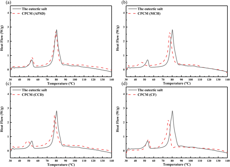 |
| | Fig. 11 DSC curves of the eutectic salt and CPCMs. | |
Table 10 Melting time and latent heat of four CPCMs
| CPCMs |
Tmelt (°C) |
ΔH (J g−1) |
| CPCM(APSD) |
76.4 |
181.3 |
| CPCM(MCH) |
74.7 |
177.5 |
| CPCM(CCD) |
76.3 |
176.4 |
| CPCM(CF) |
74.0 |
165.0 |
The thermal conductivity of the eutectic salt and four CPCMs was evaluated using a Hot Disk Thermal Constant Analyzer. The results are recorded in Table 11, and it is observed that the thermal conductivity of the mixture is the lowest among the samples tested. However, the addition of nucleating and thickening agents resulted in an improvement in thermal conductivity, suggesting that these agents can effectively increase the thermal conductivity of the eutectic salt system.
Table 11 Thermal conductivity of the eutectic salt and four CPCMs
| Sample |
Thermal conductivity (W m−1 K−1) |
| The eutectic salt |
0.3675 |
| CPCM(APSD) |
0.3982 |
| CPCM(MCH) |
0.4265 |
| CPCM(CCD) |
0.4051 |
| CPCM(CF) |
0.4010 |
3.6 Thermal cycle supercooling characteristics of CPCMs
The change of supercooling degree of the four CPCMs after thermal cycle is shown in Fig. 12. The supercooling degree test after thermal cycle was carried out at the number of cycles of 10, 20, 30, 40 and 50 respectively. It can be seen that in the initial 0th supercooling degree test, the CPCM(APSD) had the best improvement on the supercooling degree, and the MCH additive combination had a poor effect on the improvement of the supercooling degree of the eutectic salt compared with the other three systems. After several cycles of CPCM(APSD), CPCM(MCH) and CPCM(CF), the supercooling degree gradually increased to about 32 °C with the increase of the number of cycles, which was much higher than that of the initial test. The supercooling degree of CPCM(CCD) is still floating at 29 °C after many hot and cold cycles, indicating that the CPCM(CCD) still has a good performance in improving the supercooling degree after many hot and cold cycles, and it can be seen from Fig. 9 that the CPCM(CCD) has a more obvious exothermic phase transition platform, which proves that the CPCM(CCD) has a more obvious reduction effect on the eutectic salt.
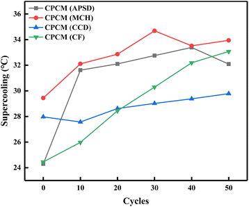 |
| | Fig. 12 Cyclic supercooling of CPCMs. | |
4. Conclusion
(1) An inorganic eutectic salt phase change material with suitable phase change temperature and high phase change enthalpy can be prepared by AASD and MSH with mass fraction ratio of 55% and 45%. The supercooling degree is 11.8 °C lower than that of single AASD hydrate salt. The phase change temperature is 76.4 °C and the latent heat reaches 189.4 J g−1.
(2) Four CPCMs (APSD, MCH, CCD and CF) were obtained by screening experiments of nucleating agent and thickening agent. The best combination system with APSD as nucleating agent was 2.0 wt% APSD/1.0 wt% SA, and the supercooling degree was 24.3 °C. The best combination system with MCH as nucleating agent is 1.5 wt% MCH/1.0 wt% SA, and the supercooling degree is 29.4 °C. The best combination system with CCD as nucleating agent was 1.0 wt% CCD/1.0 wt% SS, supercooling degree was 28.0 °C; the best combination system with CF as nucleating agent was 2.0 wt% CF/1.0 wt% SA, and the supercooling degree was 24.5 °C.
(3) The latent heat of the four CPCMs is lower than that of the eutectic salt. The incorporation of nucleating and thickening agents resulted in a reduction of latent heat, however, the latent heat of the four CPCMs remains higher than 165 J g−1, which still surpasses other phase change material systems. The addition of nucleating and thickening agents resulted in a slight increase in the thermal conductivity of the mixture in comparison to the mixture without these agents.
(4) After conducting a thermal cycle test, CPCM(CCD) was deemed the most suitable CPCM for the AASD–MSH eutectic salt. Following 50 thermal cycles, the supercooling degree was still less than 30 °C, providing valuable information for future research in this field.
Conflicts of interest
There are no conflicts to declare.
Acknowledgements
This work was supported by the National Natural Science Foundation of China (No. 51906230 and No. 51906229), and the Henan Provincial Science and Technology Key Project Fund (No. 212102210007), and the project of Zhongyuan Science and Technology Innovation Talents.
References
- T. Yan, J. Li, J. J. Gao, X. H. Xu and J. H. Yu, Appl. Therm. Eng., 2021, 194, 13 CrossRef.
- G. Alva, Y. Lin and G. Fang, Energy, 2018, 144, 341–378 CrossRef.
- P. Aggrey, M. Nartey, Y. Kan, J. Cvjetinovic, A. Andrews, A. I. Salimon, K. I. Dragnevski and A. M. Korsunsky, RSC Adv., 2021, 11, 31884–31922 RSC.
- A. A. M. Omara, J. Energy Storage, 2021, 44, 32 CrossRef.
- W. J. Hu, S. H. Lin, Y. F. Cao, X. S. Feng and Q. M. Pan, RSC Adv., 2022, 12, 15180–15189 RSC.
- H. Nazir, M. Batool, F. Osorio, M. Isaza-Ruiz, X. Xu, K. Vignarooban, P. Phelan, Inamuddin and A. M. Kannan, Int. J. Heat Mass Transfer, 2019, 129, 491–523 CrossRef CAS.
- Y. P. Wu and T. Wang, Energy Convers. Manage., 2015, 101, 164–171 CrossRef CAS.
- Z. F. Liu, Z. H. Chen and F. Yu, Sol. Energy Mater. Sol. Cells, 2019, 200, 9 Search PubMed.
- C. Z. Liu, C. Wang, Y. M. Li and Z. H. Rao, RSC Adv., 2017, 7, 7238–7249 RSC.
- B. K. Purohit and V. S. Sistla, Energy Storage, 2021, 3, 26 CrossRef.
- L. A. Lei, B. Bp, B. Cy, G. A. Min and Z. Mei, Mater. Chem. Phys., 2019, 222, 87–95 CrossRef.
- Y. X. Lin, G. Alva and G. Y. Fang, Energy, 2018, 165, 685–708 CrossRef CAS.
- H. Liu, Z. H. Zheng, Z. Q. Qian, Q. W. Wang, D. Z. Wu and X. D. Wang, Sol. Energy Mater. Sol. Cells, 2021, 229, 13 CrossRef.
- S. A. Mohamed, F. A. Al-Sulaiman, N. I. Ibrahim, M. H. Zahir, A. Al-Ahmed, R. Saidur, B. S. Yilbas and A. Z. Sahin, Renewable Sustainable Energy Rev., 2017, 70, 1072–1089 CrossRef CAS.
- L. Gang, B. Zhang, L. Xiang, Z. Yuan and Y. Qiang, Sol. Energy Mater. Sol. Cells, 2014, 126, 51–55 CrossRef.
- S. Cao, X. Luo, X. Han, X. Lu and C. Zou, Energies, 2022, 15, 12 Search PubMed.
- Y. Zhang, X. Zhang, X. Xu, J. M. Munyalo, L. Liu, X. Liu, M. Lu and Y. Zhao, J. Mol. Liq., 2019, 280, 360–366 CrossRef CAS.
- R. A. Putri, A. Yusuf, A. Rahman, Y. Anggraini, D. Kurnia, S. Wonorahardjo, S. Wonorahardjo and I. M. Sutjahja, J. Energy Storage, 2021, 42, 9 Search PubMed.
- H. Zhang, C. L. Xu and G. Y. Fang, Sol. Energy Mater. Sol. Cells, 2022, 241, 19 CrossRef.
- M. F. Junaid, Z. U. Rehman, M. Cekon, J. Curpek, R. Farooq, H. Z. Cui and I. Khan, Energy Build., 2021, 252, 29 CrossRef.
- A. Sharma, V. V. Tyagi, C. R. Chen and D. Buddhi, Renewable Sustainable Energy Rev., 2009, 13, 318–345 CrossRef CAS.
- M. M. Farid, A. M. Khudhair, S. Razack and S. Al-Hallaj, Energy Convers. Manage., 2004, 45, 1597–1615 CrossRef CAS.
- W. S. Hua, X. L. Zhang and X. C. Han, J. Therm. Anal. Calorim., 2019, 136, 1173–1183 CrossRef CAS.
- M. T. Fang, X. L. Zhang, J. Ji, W. S. Hua, Y. Zhao and J. Y. Liang, J. Therm. Anal. Calorim., 2022, 147, 8177–8188 CrossRef CAS.
- T. Wang, X. S. Zhou, Z. Liu, J. W. Wang, Y. S. Zhang and W. P. Pan, Appl. Therm. Eng., 2021, 183, 9 Search PubMed.
- G. Li, B. B. Zhang, X. Li, Y. Zhou, Q. G. Sun and Q. Yun, Sol. Energy Mater. Sol. Cells, 2014, 126, 51–55 CrossRef CAS.
- Z. Y. Li, D. Zhong, H. Zhou, Q. L. Cai, Y. Liu, L. Q. Liu and F. K. Ma, Mater. Res. Express, 2019, 6, 7 Search PubMed.
- H. Wang, L. J. Guo, K. Q. Liu, Z. C. Song, L. Wu, M. H. Fang and J. Q. Li, Mater. Res. Express, 2019, 6, 12 Search PubMed.
- J. F. Mao, P. M. Hou, R. R. Liu, F. Chen and X. Dong, Appl. Therm. Eng., 2017, 119, 585–592 CrossRef CAS.
- S. L. Xie, J. H. Sun, Z. Wang, S. Liu, L. P. Han, G. X. Ma, Y. Jing and Y. Z. Jia, Sol. Energy Mater. Sol. Cells, 2017, 168, 38–44 CrossRef CAS.
- K. Du, J. Calautit, Z. Wang, Y. Wu and H. Liu, Appl. Energy, 2018, 220, 242–273 CrossRef CAS.
- S. Zhao, S. Yan, T. Ming, C. Ao, L. Zhao and X. Zhao, J. Therm. Anal. Calorim., 2022, 147, 13239–13252 CrossRef CAS.
- Z. S. Wang, Z. W. Li, G. T. Lu, Q. Gao, R. X. Zhang and Z. L. Gu, Sustain. Cities Soc., 2022, 86, 11 CrossRef.
- X. Zhou, X. Zhang and Q. Zheng, Energy Fuels, 2020, 34, 7607–7615 CrossRef CAS.
- R. D. Ye, H. Jiang, J. Wang, X. A. Yang and X. G. Shu, Sol. Energy Mater. Sol. Cells, 2022, 238, 10 CrossRef.
- C. H. Zhu, B. G. Li, H. F. Yang and Q. Q. Luo, Int. J. Energy Res., 2020, 44, 2061–2071 CrossRef CAS.
- M. Kenisarin and K. Mahkamov, Sol. Energy Mater. Sol. Cells, 2016, 145, 255–286 CrossRef CAS.
- B. K. Purohit and V. S. Sistla, J. Energy Storage, 2017, 12, 196–201 CrossRef.
- A. Sayigh, Solar & Wind Technology, 1987, 4, 239 Search PubMed.
- S. F. Wu, T. Yan, Z. H. Kuai and W. G. Pan, Sol. Energy, 2020, 205, 474–486 CrossRef CAS.
- W. C. Sun, Y. Zhou, J. X. Feng, X. M. Fang, Z. Y. Ling and Z. G. Zhang, Molecules, 2019, 24, 15 Search PubMed.
- M. Khandagre, B. Gupta, J. Bhalavi and P. Baredar, J. Therm. Eng., 2021, 7, 196–214 CrossRef.
- A. Abhat, Sol. Energy, 1983, 30, 313–332 CrossRef CAS.
- L. F. Cabeza, A. Castell, C. Barreneche, A. de Gracia and A. I. Fernandez, Renewable Sustainable Energy Rev., 2011, 15, 1675–1695 CrossRef CAS.
- Z. Y. Ling, J. W. Liu, Q. H. Wang, W. Z. Lin, X. M. Fang and Z. G. Zhang, Sol. Energy Mater. Sol. Cells, 2017, 172, 195–201 CrossRef CAS.
- H. Schmit, D. Rudaleviciene, C. Rathgeber and S. Hiebler, J. Energy Storage, 2020, 27, 7 Search PubMed.
- S. Hohlein, A. Konig-Haagen and D. Bruggemann, Materials, 2017, 10, 15 CrossRef PubMed.
- G. X. Ma, S. Liu, S. L. Xie, Y. Jing, Q. Y. Zhang, J. H. Sun and Y. Z. Jia, Appl. Therm. Eng., 2017, 111, 1052–1059 CrossRef CAS.
- X. C. Zhou, X. L. Zhang and Q. Y. Zheng, Sol. Energy Mater. Sol. Cells, 2020, 217, 19 CrossRef.
|
| This journal is © The Royal Society of Chemistry 2023 |
Click here to see how this site uses Cookies. View our privacy policy here.  Open Access Article
 *,
Yinlei Li,
Jun Song
 ,
XueLing Zhang,
Xuehong Wu,
Chongyang Liu and
Yanfang Li


