 Open Access Article
Catalytic effects of Ni nanoparticles encapsulated in few-layer N-doped graphene and supported by N-doped graphitic carbon in Li–S batteries†
Nurzhan Baikalov a,
Islam Rakhimbekb,
Aishuak Konarov
 a,
Almagul Mentbayeva
 a,
Yongguang Zhang
 c and
Zhumabay Bakenov
 *ab
*ab
aDepartment of Chemical and Materials Engineering, Nazarbayev University, Astana 010000, Kazakhstan. E-mail: zbakenov@nu.edu.kz
bNational Laboratory Astana, Nazarbayev University, Astana 010000, Kazakhstan
cSchool of Materials Science and Engineering, State Key Laboratory of Reliability and Intelligence of Electrical Equipment, Hebei University of Technology, Tianjin 300130, China
First published on 22nd March 2023
Abstract
Although lithium–sulfur batteries possess the highest theoretical capacity and lowest cost among all known rechargeable batteries, their commercialization is still hampered by the intrinsic disadvantages of low conductivity of sulfur and polysulfide shuttle effect, which is most critical. Considerable research efforts have been dedicated to solving these difficulties for every part of Li–S batteries. Separator modification with metal electrocatalysts is a promising approach to overcome the major part of these disadvantages. This work focuses on the development of Ni nanoparticles encapsulated in a few-layer nitrogen-doped graphene supported by nitrogen-doped graphitic carbon (Ni@NGC) with different metal loadings as separator modifications. The effect of metal loading on the Li–S electrochemical reaction kinetics and performance of Li–S batteries was investigated. Controlling the Ni loading allowed for the modulation of the surface area-to-metal content ratio, which influenced the reaction kinetics and cycling performance of Li–S cells. Among the separators with different Ni loadings, the one with 9 wt% Ni exhibited the most efficient acceleration of the polysulfide redox reaction and minimized the polysulfide shuttling effect. Batteries with this separator retained 77.2% capacity after 200 cycles at 0.5C, with a high sulfur loading of ∼4.0 mg cm−2, while a bare separator showed 51.3% capacity retention after 200 cycles under the same conditions. This work reveals that there is a vast utility space for carbon-encapsulated Ni nanoparticles in electrochemical energy storage devices with optimal selection and rational design.
1 Introduction
Lithium–sulfur (Li–S) batteries have been extensively studied over the past few decades due to the extremely high theoretical specific capacity of sulfur (1675 mA h g−1) and appropriate operating potential, as well as low cost, non-toxicity, abundance and environmental friendliness of sulfur resources.1,2 However, the commercialization of Li–S batteries is severely hampered by the difficulties associated with poor conductivity, large volume variations (80%) of sulfur upon charge–discharge cycling, and complicated redox reactions.3 The complexity of the redox reaction is associated with the formation of lithium polysulfides (LiPSs) that readily dissolve in the electrolyte and shuttle from the cathode to the anode to produce non-reusable solid Li2S2/Li2S.4 This process is accompanied by a constant loss of active material and passivation of the anode surface, and it is regarded to be one of the most critical issues that limits the practical use of Li–S batteries. Moreover, a multiphase solid–liquid–solid sulfur/LiPSs/sulfide conversion is sluggish at the electrode/electrolyte interface due to the insulating nature of sulfur and lithium sulfide.5 In this regard, it is crucial to develop advanced sulfur-based cathode materials to accelerate the sulfur redox reaction, inhibit the dissolution of LiPSs and restrict their shuttle/diffusion.Tremendous efforts have been made to enhance the LiPS conversion reaction kinetics and affinity of the conductive host material to LiPSs (physical blocking and chemical adsorption). Because of their high conductivity and large surface area, carbon materials including graphenes, carbon nanotubes (CNTs), carbon nanofibers (CNFs), and porous carbon materials are frequently employed in Li–S batteries.2,6,7 However, physical adsorption is frequently ineffective at suppressing LiPS dissolution, but chemical interaction can efficiently anchor polar LiPS and inhibit their diffusion in the electrochemical processes of Li–S batteries.8 Active materials such as transition metal compounds (-oxides,9–11 -sulfides,12–14 -nitrides,15–17 etc.) exhibit strong chemical attraction to polar LiPS and enhance the reversible redox kinetics of sulfur compounds. Nevertheless, the poor conductivity of these active materials would adversely affect the confinement of the LiPS. Moreover, the sluggish redox kinetics of the immobilized LiPS on these active materials would result in low utilization of sulfur and poor electrochemical performance of Li–S batteries.18 In this regard, combination of a conductive carbon matrix with chemical/physical adsorption ability and a metal with catalytic effects towards the reaction of solid–liquid, liquid–liquid and liquid–solid conversion of sulfur species is of great value for the construction of high-rate Li–S batteries.19–22
Increasing attention has recently been paid to the use of conductive metal electrocatalysts to boost the rate of electrochemical reactions in Li–S batteries. The promising electrocatalytic activity of single atoms and metal nanoparticles has been studied extensively as effective modification for host materials, interlayer membranes and separators.23–25 Among them, the separator modification is considered as a relative simple method that also eliminates direct mixing of sulfur and the material to avoid oxidation, which may affect the conductivity of carbon materials.26,27 Recently, due to their promising electrocatalytic activity, Ni nanoparticles and single atoms have been extensively studied for the separator modification. Yang et al. reported that Ni nanoparticles and Ni3Fe in nitrogen-doped carbon nanotubes (Ni@NCNTs and Ni3Fe@NCNTs) can increase the reaction rate of liquid–liquid and liquid–solid conversion compared with the bare NCNT material, from the results of symmetric cells and Li2S nucleation.19 Xie et al. reported that graphene-impregnated Ni, Fe, and Co single atoms efficiently modified separators, reduced the potential gap and improved the cycle life of Li–S batteries.21 Niu et al. reported that Ni single atoms are partially oxidized and formed a Ni–N4 structure, which can act as a polysulfide trap.28 In this regard, efficient immobilization of metal electrocatalysts and understanding the role of metal content/loading within a carbon matrix on the electrochemical reaction kinetics are critically important. However, such studies have rarely been reported in the literature up to date.
Herein, Ni nanoparticles encapsulated in a few-layer N-doped graphene supported by nitrogen-doped graphitic carbon (Ni@NGC) with different metal loadings were designed as separator modificators. Ni@NGC with different metal loadings of 18, 12, 9 and 7 wt%, denoted further as Ni@NGC_18, Ni@NGC_12, Ni@NGC_9 and Ni@NGC_7, respectively, were synthesized via carbonization and hot acidic treatment of a mixture of urea and Ni acetylacetonate taken in different molar ratios. With the increase in the molar ratio of urea, the formation of nanotubes on the surface of stacked sheets increased, which, in turn, favored the development of porous structures with a large active surface area. N-doped graphitic carbon and Ni nanoparticles, dispersed in the matrix, form a highly conductive network, which is beneficial for a rapid electron transfer between LiPSs and the carbon matrix. The encapsulation of Ni nanoparticles with several layers of N-doped graphenes eliminates the direct contact of metal nanoparticles with LiPSs, and thus suppresses their oxidization by LiPSs. The effect of Ni@NGC modification with 18, 12, 9 and 7 wt% Ni loadings on the reaction kinetics and their interaction with LiPSs were investigated. Modified separators with 9 wt% Ni (Ni@NGC_9) demonstrated improved reaction kinetics and cycling performance due to the optimized surface area-to-Ni content ratio.
2 Experimental section
2.1 Preparation of Ni@NGC-coated separators
Nickel acetylacetonate (Ni(acac)2) and urea were carefully mixed in different molar ratios (1![[thin space (1/6-em)]](https://www.rsc.org/images/entities/char_2009.gif) :
:![[thin space (1/6-em)]](https://www.rsc.org/images/entities/char_2009.gif) 7.5, 1
7.5, 1![[thin space (1/6-em)]](https://www.rsc.org/images/entities/char_2009.gif) :
:![[thin space (1/6-em)]](https://www.rsc.org/images/entities/char_2009.gif) 9, 1
9, 1![[thin space (1/6-em)]](https://www.rsc.org/images/entities/char_2009.gif) :
:![[thin space (1/6-em)]](https://www.rsc.org/images/entities/char_2009.gif) 12 and 1
12 and 1![[thin space (1/6-em)]](https://www.rsc.org/images/entities/char_2009.gif) :
:![[thin space (1/6-em)]](https://www.rsc.org/images/entities/char_2009.gif) 15) and heated at 900 °C for one hour in an argon atmosphere at a ramp rate of 3 °C min−1. The resulting black powder was treated with 0.5 M H2SO4 at 130 °C for 12 h. The final product was washed with DI water until the pH reached 7 and dried at 40 °C for 24 h under vacuum. The NGC compound preparation involves treating Ni@NGC (in 1
15) and heated at 900 °C for one hour in an argon atmosphere at a ramp rate of 3 °C min−1. The resulting black powder was treated with 0.5 M H2SO4 at 130 °C for 12 h. The final product was washed with DI water until the pH reached 7 and dried at 40 °C for 24 h under vacuum. The NGC compound preparation involves treating Ni@NGC (in 1![[thin space (1/6-em)]](https://www.rsc.org/images/entities/char_2009.gif) :
:![[thin space (1/6-em)]](https://www.rsc.org/images/entities/char_2009.gif) 15 molar ratio) with concentrated hydrochloric acid (HCl) at 70 °C for 24 hours with continuous stirring.19 Modified separators were prepared by a vacuum filtration method.29 Shortly, 90 mg active materials and 10 mg of polyvinylidene fluoride (PVDF) were added into a N-methylpyrrolidone solvent and ball-milled at 400 rpm for 4 h to form a homogeneous dispersion. Afterward, the dispersion was coated onto a commercial polypropylene (PP, Celgard-2400) separator and dried in a vacuum oven. After drying, the modified separator was punched into disks with a diameter of 19 mm. The areal mass loading of Ni@NGC was controlled to be ∼0.1 mg cm−2.
15 molar ratio) with concentrated hydrochloric acid (HCl) at 70 °C for 24 hours with continuous stirring.19 Modified separators were prepared by a vacuum filtration method.29 Shortly, 90 mg active materials and 10 mg of polyvinylidene fluoride (PVDF) were added into a N-methylpyrrolidone solvent and ball-milled at 400 rpm for 4 h to form a homogeneous dispersion. Afterward, the dispersion was coated onto a commercial polypropylene (PP, Celgard-2400) separator and dried in a vacuum oven. After drying, the modified separator was punched into disks with a diameter of 19 mm. The areal mass loading of Ni@NGC was controlled to be ∼0.1 mg cm−2.
2.2 Materials characterization
The nanostructure and morphology were analyzed by scanning electron microscopy (SEM, Zeiss Crossbeam 540, 5 kV) and transmission electron microscopy (TEM, JEOL JEM-1400PLUS, 200 kV). The crystal structure was studied by X-ray diffraction (XRD, Rigaku Smartlab) in the 2θ range of 15° to 90° with Cu Kα radiation (λ = 1.54056 Å). Raman spectra were recorded using a spectrometer (Horiba LabRam Evolution). Thermal gravimetric analysis of the samples was carried out using a Simultaneous Thermal Analyzer (STA 6000, PerkinElmer). The measurements of specific surface area and pore volumes were conducted via N2 adsorption and desorption isotherms (nitrogen porosimeter, Quantachrome Instruments), while the pore size distribution was determined by the Barrett–Joyner–Halenda (BJH) method. The oxidation state changes were investigated by X-ray photoelectron spectroscopy (XPS, NEXSA, Thermo Scientific).2.3 LiPS permeability test
The LiPS permeability of the Ni@NGC-modified separator was studied using a UV-vis spectrophotometer. The sample preparation was carried out by placing modified separators into a blue screw cap with a hole vial (2 mL) filled with 5 mM solution of Li2S6 dissolved in 1,2-dimetoxyethane (DME) and 1,3-dioxolane (DOL) (1![[thin space (1/6-em)]](https://www.rsc.org/images/entities/char_2009.gif) :
:![[thin space (1/6-em)]](https://www.rsc.org/images/entities/char_2009.gif) 1, v/v) and letting small vials stay inside a larger vial filled with a DOL/DME (1
1, v/v) and letting small vials stay inside a larger vial filled with a DOL/DME (1![[thin space (1/6-em)]](https://www.rsc.org/images/entities/char_2009.gif) :
:![[thin space (1/6-em)]](https://www.rsc.org/images/entities/char_2009.gif) 1, v/v) solvent for 12 hours. Fully adsorbed samples were recovered and dried for further XPS analysis.
1, v/v) solvent for 12 hours. Fully adsorbed samples were recovered and dried for further XPS analysis.
2.4 Symmetric cell test
In order to prepare the electrodes for a symmetrical cell, a slurry of the active materials (Ni@NGC with different Ni wt% loadings) uniformly mixed and dispersed in NMP was dropped onto a circular carbon paper current collector and dried in a vacuum oven at 60 °C for 6 hours. Symmetric cells were assembled from two identical electrodes separated by a commercial Celgard® 2400 separator. A solution of 0.3 M Li2S6 in DOL/DME (1![[thin space (1/6-em)]](https://www.rsc.org/images/entities/char_2009.gif) :
:![[thin space (1/6-em)]](https://www.rsc.org/images/entities/char_2009.gif) 1, v/v) was used as an electrolyte with 50 μL of it dropped between the electrodes. The CV investigation of the polysulfide behaviour was conducted using a Biologic VMP3 potentiostat/galvanostat at a scan rate of 10 mV s−1 in the potential range from −1.0 V to 1.0 V vs. Li/Li+.
1, v/v) was used as an electrolyte with 50 μL of it dropped between the electrodes. The CV investigation of the polysulfide behaviour was conducted using a Biologic VMP3 potentiostat/galvanostat at a scan rate of 10 mV s−1 in the potential range from −1.0 V to 1.0 V vs. Li/Li+.
2.5 Nucleation test
The prepared material loaded onto carbon paper was used as a working electrode with a metallic Li counter/reference electrode, 20 μL of 0.5 M Li2S8 in tetraglyme as a catholyte and 20 μL 1 M (lithium bis(trifluoromethanesulfonyl)imide) LiTFSI with 2 wt% of LiNO3 in DOL/DME (1![[thin space (1/6-em)]](https://www.rsc.org/images/entities/char_2009.gif) :
:![[thin space (1/6-em)]](https://www.rsc.org/images/entities/char_2009.gif) 1, v/v) as an anolyte. Assembled CR 2032 coin cells were galvanostatically discharged up to 2.06 V and further kept at 2.05 V until the current dropped below 10−5 A for Li2S nucleation.
1, v/v) as an anolyte. Assembled CR 2032 coin cells were galvanostatically discharged up to 2.06 V and further kept at 2.05 V until the current dropped below 10−5 A for Li2S nucleation.
2.6 Electrochemical characterization
The Li–S coin cells were assembled using Li metal as the counter/reference electrode, the Li2S6 catholyte as the active material, carbon paper as the cathode current collector, and commercial or the modified separator. The sulfur content, calculated based on the sulfur content in the Li2S6 solution, was ∼4.0 mg cm−2, for which 16 μL of 1 M Li2S6 solution was used in each cell. Then, 10 μL of the electrolyte in the cathode (sulfur) side and 20 μL in the anode (lithium) side were added. Thus, the ratio of the electrolyte and sulfur was controlled as 10![[thin space (1/6-em)]](https://www.rsc.org/images/entities/char_2009.gif) :
:![[thin space (1/6-em)]](https://www.rsc.org/images/entities/char_2009.gif) 1. The 1 M LiTFSI electrolyte was prepared by dissolving LiTFSI in DOL/DME (1
1. The 1 M LiTFSI electrolyte was prepared by dissolving LiTFSI in DOL/DME (1![[thin space (1/6-em)]](https://www.rsc.org/images/entities/char_2009.gif) :
:![[thin space (1/6-em)]](https://www.rsc.org/images/entities/char_2009.gif) 1, v/v) with the 0.1 M LiNO3 additive. The galvanostatic charge–discharge tests were carried out within the potential range of 1.7–2.8 V vs. Li/Li+ using a Neware battery tester (Neware Co.). Cyclic voltammetry (CV) curves were obtained using a Biologic VMP3 potentiostat/galvanostat in the potential range of 1.7–2.8 V, and electrochemical impedance spectroscopy (EIS) was performed in the frequency range from 100 kHz to 1 MHz at an amplitude of 5 mV.
1, v/v) with the 0.1 M LiNO3 additive. The galvanostatic charge–discharge tests were carried out within the potential range of 1.7–2.8 V vs. Li/Li+ using a Neware battery tester (Neware Co.). Cyclic voltammetry (CV) curves were obtained using a Biologic VMP3 potentiostat/galvanostat in the potential range of 1.7–2.8 V, and electrochemical impedance spectroscopy (EIS) was performed in the frequency range from 100 kHz to 1 MHz at an amplitude of 5 mV.
2.7 In situ Raman measurements
The Raman spectra were recorded in a CR2032 cell with a hole on the cathode side of the cell sealed by a piece of glass using a spectrometer (Horiba LabRam Evolution) and a 532 nm laser and a microscope objective of ×10 K magnification under ambient conditions. The cell was first charged to 2.8 V and then the Raman signals were recorded every 5 minutes throughout the discharging–charging cycling of the Li–S cell.3 Results and discussion
3.1 Characterization of Ni@NGC
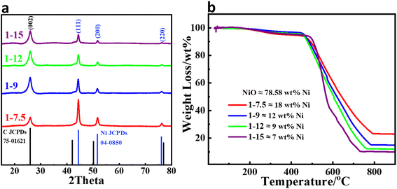
The Ni NPs encapsulated in a few-layer N-doped graphene supported by N-doped graphitic carbon with different metal loadings were synthesized by pyrolysis of a Ni(acac)2 precursor in the presence of urea followed by hot acidic treatment. Fig. 1a shows the XRD patterns of Ni@NGC with different Ni loadings. The diffraction peaks at 2θ 44.5°, 51.8°, and 76.3° can be assigned to the (111), (200), and (220) planes of the Ni NPs (JCPDS 04-0850), respectively, where the peak centered at 26.2° corresponds to the (002) plane of graphitic carbon (JCPDS 75-1621). TGA analysis demonstrated that the Ni contents in the Ni@NGC samples with the initial precursors' ratio equal to 1![[thin space (1/6-em)]](https://www.rsc.org/images/entities/char_2009.gif) :
:![[thin space (1/6-em)]](https://www.rsc.org/images/entities/char_2009.gif) 7.5, 1
7.5, 1![[thin space (1/6-em)]](https://www.rsc.org/images/entities/char_2009.gif) :
:![[thin space (1/6-em)]](https://www.rsc.org/images/entities/char_2009.gif) 9, 1
9, 1![[thin space (1/6-em)]](https://www.rsc.org/images/entities/char_2009.gif) :
:![[thin space (1/6-em)]](https://www.rsc.org/images/entities/char_2009.gif) 12 and 1
12 and 1![[thin space (1/6-em)]](https://www.rsc.org/images/entities/char_2009.gif) :
:![[thin space (1/6-em)]](https://www.rsc.org/images/entities/char_2009.gif) 15 in the final samples corresponded to 18, 12, 9 and 7 wt% Ni, respectively (denoted as Ni@NGC_18, Ni@NGC_12, Ni@NGC_9 and Ni@NGC_7) (Fig. 1b).
15 in the final samples corresponded to 18, 12, 9 and 7 wt% Ni, respectively (denoted as Ni@NGC_18, Ni@NGC_12, Ni@NGC_9 and Ni@NGC_7) (Fig. 1b).
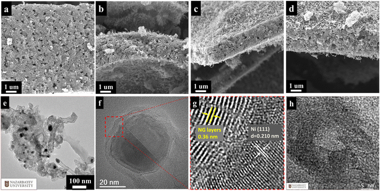
Fig. 2a–d presents the SEM images of Ni@NGC with different Ni contents, and shows that they have stacked sheet-like morphology in the presence of nitrogen-doped carbon nanotubes (CNTs) that originate from the decomposition of urea with the aid of nickel catalysts.30 Uniformly distributed Ni nanoparticles with a diameter of 20–25 nm can be observed from a low-magnification TEM image of Ni@NGC_9 (Fig. 2e). High-resolution TEM images indicate that the Ni NPs are encapsulated in several layers of the graphene shell (Fig. 2f). In the graphene shell region, the interlayer distance is around 0.36 nm, confirming that the Ni NPs are coated by the graphene layers (Fig. 1g). The well-resolved lattice fringes with a d-spacing of 0.210 in the Ni core region can be clearly observed by HRTEM, which corresponds to the (111) plane of Ni NPs (Fig. 1b). Fig. 2h shows the TEM image of the NGC material, where the formation of onion-like nanostructures can be observed, which are formed due to the removal of the Ni NPs from the N-doped graphene shells after the HCl acidic treatment. The NGC material showed a morphology similar to that of Ni@NGC, with the thickness of the coating of commercial separator (Celgard 2400) around 6 μm.
Fig. 3a displays the Raman spectra of NGC and Ni@NGC samples in the Raman shift ranging from 900 cm−1 to 2800 cm−1. Two peaks at about 1350 cm−1 and 1580 cm−1 found in all spectra are the characteristic features of carbonaceous materials. The peak at 1350 cm−1 (D band) corresponds to the defect in the carbon structure, whereas the peak at 1580 cm−1 (G band) has risen due to the graphitic carbon. The intensity ratio of the D and G bands (ID/IG) is increasing with the increase in the molar ratio of urea precursor, suggesting a higher degree of disorder and formation of carbon nanotubes in Ni@NGC, which is consistent with the XRD and SEM results.
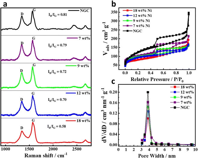 | ||
| Fig. 3 (a) Raman spectra, (b) nitrogen adsorption desorption isotherms, and (c) pore size distribution of Ni@NGC with different Ni loadings. | ||
The porous structure of the samples was further investigated by nitrogen adsorption–desorption measurements (Fig. 3b). Ni@NGC exhibited a type IV hysteresis in the relative pressure region of 0.4–0.9 P/P0 and moderately smooth adsorption curves throughout the whole relative pressure region, indicating the presence of mesopores.31,32 The respective pore size distribution is also shown in Fig. 3c, which was calculated by the Barrett–Joyner–Halenda (BJH) method. According to BJH, the average pore size of Ni@NGC materials was about 3.8 nm, and the corresponding BJH desorption cumulative pore volume was found to be equal to 0.101, 0.127, 0.144, 0.162 and 0.197 cm3 nm−1 g−1, while the specific surface area was calculated to be 93.5, 104.4, 117.1, 123.6 and 131.4 m2 g−1, for Ni@NGC_18, Ni@NGC_12, Ni@NGC_9, Ni@NGC_7 and NGC, respectively. Thus, controlling the molar ratio of Ni precursor to urea followed by hot acidic solution treatment is a key approach to increase the cumulative pore volume and surface area of Ni@NGC materials.
The surface composition and oxidation states of the Ni@NGC-modified separators were retrieved from the XPS analysis. The general survey spectrum (Fig. 4a) confirmed the presence of Ni, C, O, and N elements in the Ni@NGC samples with different Ni wt% loadings. The C 1s XPS spectrum (Fig. 4b) was deconvoluted into three peaks at 284.5, 285.8, and 288.5 eV, which corresponded to those of the C–C, C–N, and C–O groups, respectively, among which the C–C bonds were more dominant than others and nitrogen-doping of graphene layers was confirmed by the presence of the C–N bonds.33 High-resolution N 1s spectrum (Fig. 4c) revealed different N-doping structures including pyridinic N at 398.4 eV, pyrrolic N at 399.4 eV, graphitic N at 400.5.0 eV and oxidized N at 403.8 eV. The contribution of each nitrogen structure was in the enhancement of the electronic conductivity and facilitating the surface adsorption ability of the carbon matrix by acting as a Lewis base substrate for polysulfide species.34,35 The Ni 2p region showed the presence of peaks of 2p3/2, 2p1/2 and satellites, which could be assigned to the binding energies of metallic nickel (Fig. S1†).
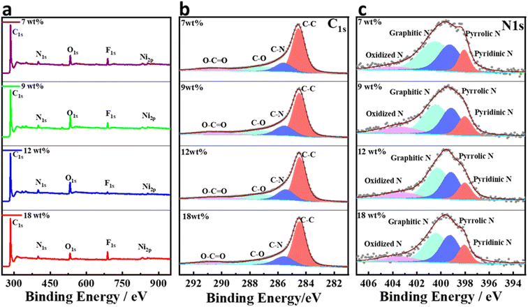 | ||
| Fig. 4 Surface XPS spectra of modified separators; (a) the general XPS survey; (b) C 1s core-level XPS spectrum; (c) N 1s core-level XPS spectrum. | ||
3.2 Kinetic behavior of modified separators
The effect of Ni@NGC-modified separators on the sulfur cathode redox reaction kinetics in Li–S cells was investigated. Fig. 5 shows the representative CV profiles of Li–S cells employing the modified separator with Ni@NGC at different scanning rates from 0.1 to 0.5 mV s−1 between 1.7 and 2.8 V vs. Li/Li+. According to the Randles–Sevcik equation, there is a linear relationship between the redox peak current and the square root of the scan rate, which allows us to evaluate the diffusion of lithium ions within the electrodes:36| Ip = 2.69 × 10⁵ × n1.5 × A × DLi+0.5 × CLi+ × v0.5 | (1) |
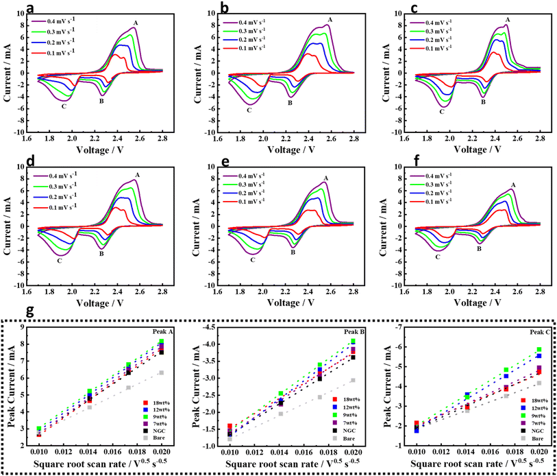 | ||
| Fig. 5 Cyclic voltammetry at different scanning rates; (a) Ni@NGC_18, (b) Ni@NGC_12, (c) Ni@NGC_9 (d) Ni@NGC_7, (e) NGC and (f) bare separator, and (g) linear fits of the peak currents. | ||
The fitted slope values of the A, B and C redox peaks of the CV plots of Ni@NGC and unmodified separators (Fig. 5) were linear with the square root of scanning rates, indicative of the diffusion-limited process. The diffusion coefficient DLi+ was calculated from the slope of the curve (Ip/v0.5), which represented the lithium ion diffusion rate, while other parameters such as the area of electrode, number of electrons and the concentration of lithium ions in the electrolyte remained unchanged (Table 1).22 It can clearly be seen that the Ni@NGC_9 sample exhibited the highest lithium ion diffusivity at the peaks A and C, which mainly arose from improved lithium polysulfide adsorption and enhanced LiPS-to-Li2S conversion capability.
| DLi+ (cm2 s−1) | Peak A | Peak B | Peak C |
|---|---|---|---|
| Ni@NGC_18 | 1.864 × 10⁻⁷ | 1.369 × 10⁻⁷ | 7.298 × 10⁻⁷ |
| Ni@NGC_12 | 3.914 × 10⁻⁷ | 2.067 × 10⁻⁷ | 7.561 × 10⁻⁷ |
| Ni@NGC_9 | 4.064 × 10⁻⁷ | 1.961 × 10⁻⁷ | 7.638 × 10⁻⁷ |
| Ni@NGC_7 | 2.274 × 10⁻⁷ | 1.618 × 10⁻⁷ | 7.321 × 10⁻⁷ |
| NGC | 1.147 × 10⁻⁷ | 1.427 × 10⁻⁷ | 6.494 × 10⁻⁷ |
| Bare | 3.831 × 10⁻⁷ | 0.822 × 10⁻⁷ | 3.535 × 10⁻⁷ |
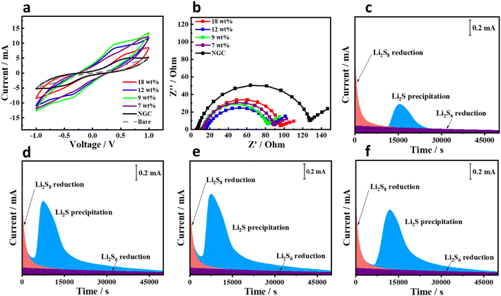
The cells were further investigated to analyze the influence of the nickel content (Ni wt%) in the Ni@NGC material on the electrochemical kinetics. Symmetric Li2S6 cells were assembled with identical electrodes prepared from Ni@NGC, NGC-loaded CFP or bare CFP. The CV profiles in Fig. 6a show that the peak current of the Ni@NGC_9 cell is higher than that of other counterparts, Ni@NGC, NGC or bare CFP. This phenomenon suggests the faster liquid–liquid conversion of LiPSs on the electrode surface, as previously reported by Koratkar et al. for the kinetics study of symmetric cells.19 It is consistent with the EIS results, where the Ni@NGC_9 sample has the lowest resistance compared to other samples showing a lower charge-transfer resistance (Fig. 6b). To evaluate the Li2S nucleation on the Ni@NGC electrode surface, the potentiostatic discharge at 2.05 V was performed using a Li2S6 catholyte. As shown in Fig. 6c–f, the cells with Ni@NGC_9 and Ni@NGC_12 reached the highest current after approximately 10![[thin space (1/6-em)]](https://www.rsc.org/images/entities/char_2009.gif) 000 seconds, indicating accelerated Li2S growth compared with Ni@NGC_18 and Ni@NGC_7, which achieved the same currents after ∼17
000 seconds, indicating accelerated Li2S growth compared with Ni@NGC_18 and Ni@NGC_7, which achieved the same currents after ∼17![[thin space (1/6-em)]](https://www.rsc.org/images/entities/char_2009.gif) 000 and ∼16
000 and ∼16![[thin space (1/6-em)]](https://www.rsc.org/images/entities/char_2009.gif) 000 seconds, respectively. Specifically, the Li2S nucleation capacities on Ni@NGC were calculated as 64, 121.3, 128.7 and 118.2 mA h g−1 for Ni@NGC with 18, 12, 9 and 7 wt% Ni, respectively. Ni@NGC_9 showed the higher activity toward Li2S precipitation, indicating its improved catalytic effect for the liquid–solid redox reaction. The SEM images of Ni@NGC_9-loaded carbon paper before and after discharge are illustrated in Fig. S3.† The SEM image before the test shows the even distribution of the Ni@NGC_9 material within the carbon fibers (Fig. S3a†). In addition, the post cycling morphology clearly shows the deposition of Li2S on the surface of carbon fibers and Ni@NGC_9. Moreover, there is a higher deposition of Li2S on the surface of Ni@NGC, further confirming the catalytic effect of Ni@NGC_9.
000 seconds, respectively. Specifically, the Li2S nucleation capacities on Ni@NGC were calculated as 64, 121.3, 128.7 and 118.2 mA h g−1 for Ni@NGC with 18, 12, 9 and 7 wt% Ni, respectively. Ni@NGC_9 showed the higher activity toward Li2S precipitation, indicating its improved catalytic effect for the liquid–solid redox reaction. The SEM images of Ni@NGC_9-loaded carbon paper before and after discharge are illustrated in Fig. S3.† The SEM image before the test shows the even distribution of the Ni@NGC_9 material within the carbon fibers (Fig. S3a†). In addition, the post cycling morphology clearly shows the deposition of Li2S on the surface of carbon fibers and Ni@NGC_9. Moreover, there is a higher deposition of Li2S on the surface of Ni@NGC, further confirming the catalytic effect of Ni@NGC_9.
3.3 Interaction between polysulfides and Ni@NGC
Impermeability to soluble polysulfides is a key requirement for a separator in the Li–S battery. In the case of the Ni@NGC-modified separators, a lower diffusion of polysulfides across the separator was detected after 12 h, as shown in Fig. 7, exhibiting effective blocking. The visual adsorption studies clearly showed that lithium polysulfide impermeability was noticeably improved on the Ni@NGC-modified separators. The modified separators' adsorption capacity towards lithium polysulfide was further analyzed by ultraviolet-visible (UV-vis) absorption tests (Fig. 7b). The results indicated that polysulfide ions contributed to an adsorption peak between 200 and 350 nm, while the Ni@NGC_9 cell displayed a reduced intensity of this peak, suggesting increased impermeability.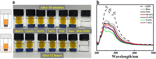 | ||
| Fig. 7 Impermeability tests of Ni@NGC-modified separators: (a) polysulfide permeation tests with Ni@NGC-modified separators; (b) comparison of UV-vis spectra after Li2S6 adsorption. | ||
The surface composition and oxidation states of the Ni@NGC-modified separators before and after full adsorption of LiPSs were characterized by XPS analysis (Fig. 8) to investigate the interaction between LiPSs and Ni@NGC. The high-resolution Ni 2p XPS spectrum of the Ni 2p3/2 region before adsorption tests revealed several peaks corresponding to the binding energies of metallic Ni (852.3 eV), Ni2+ (855.5 eV), Ni3+ (862.0 eV) and the satellite peak (858.7 eV), indicating that Ni nanoparticles were present in the form of Ni0, Ni2+, and Ni3+ in the composites. The peak fitting results demonstrated a decrease in the Ni3+ content as the content of Ni wt% decreased as Ni3+ was reduced to Ni2+ with the increase in carbon amount.35 Nevertheless, the appearance of Ni2+ might be attributed to surface oxidation because of the exposure to the air. In contrast, the Ni 2p3/2 spectrum of Ni@NGC-Li2S6 showed characteristic peaks upshifted to higher binding energies and an increased intensity in the Ni2+ region, indicating the electron transfer from surface-exposed nickel atoms to electron-rich sulfur atoms in Li2S6 (Fig. 8b and c).19 Moreover, Ni@NGC_9 demonstrated higher generation of thiosulfate species (S2O32−) and a polythionate complex (SxO62−) used as a polysulfide shuttle suppressing the transfer mediator.35 Likewise, the Li2S2 peak was formed with a higher intensity with Ni@NGC_9 pointing at a more efficient lithium polysulfide conversion into lithium sulfides in contrast to other samples.37
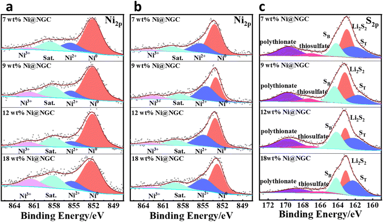 | ||
| Fig. 8 Illustration of the anchoring mechanism of polysulfides. Ni 2p region (a) before and (b) after adsorption of Li2S6; (c) S 2p XPS spectra of Ni@NGC-modified separators after adsorption. | ||
3.4 Cycling performance of functional Ni@NGC-modified separators
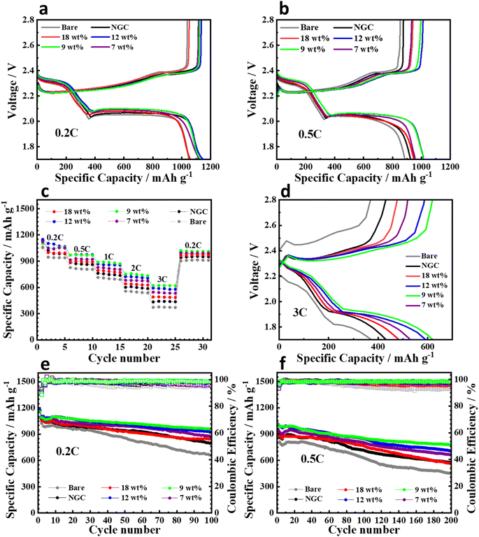
To study the performance of the cells with the modified separators, Li–S cells were assembled using standard CR2032 coin cells with a high sulfur loading of ∼4.0 mg cm−2. The cell with the Ni@NGC_9 sample showed lower polarization in the charge–discharge operation at 0.2 and 0.5C rates and exhibited specific capacities of 1028.3, 887.7, 800.1, 747.8, 651.2, and 598.0 mA h g−1 at 0.2, 0.5, 1, 2, and 3C rates, respectively, which exceeded those of other samples of Ni@NGC, NGC, and pristine PP separator (Fig. 9a–c). Fig. 9a shows that the cells with Ni@NGC_9, Ni@NGC_12 and NGC show a similar initial capacity at a lower current density, which can be explained with the effects of specific surface area and Ni content. Despite having a lower Ni content, the cell with Ni@NGC_9 demonstrated a similar capacity to the cell with Ni@NGC_12, which could be attributed to a higher specific surface area (117.1 and 104.4 m2 g−1, respectively). In contrast, the capacity of the cell with NGC was comparable to that of the cells with Ni@NGC_9 and Ni@NGC_12 due to the increased specific surface area (131.4 m2 g−1). At a higher current density, the cells with Ni@NGC_9 and Ni@NGC_12 exhibited a higher capacity than NGC, which can be explained by an improved reaction kinetics for the cells with Ni@NGC_9 and Ni@NGC_12 (Fig. 9b). Even at a high 3C rate, Ni@NGC_9 maintained a smaller polarization between the charge and discharge potential plateaus than the cells with other, Ni@NGC and NGC, modifications, and bare PP separators at 3C rate (Fig. 9d). Longer plateaus at 3C in charge–discharge curves for Ni@NGC_9 indicate an increased polysulfide adsorption capability and a stronger catalytic effect for the conversion of insoluble Li2S into polysulfides, and vice versa, in the cell. Moreover, the Ni@NGC_9 sample showed a better cycling stability with a high initial capacity of about 1127 and 1005 mA h g−1 at 0.2 and 0.5C rates, with a capacity retention of 83% and 77% after 100 and 200 cycles, respectively (Fig. 9e and f). In contrast, the Ni@NGC_12 sample, despite the higher initial capacities (1148 mA h g−1 at 0.2C and 1012 mA h g−1 at 0.5C), showed a lower capacity retention after 100 cycles at 0.2C (78.9%) and 200 cycles at 0.5C (69.9%). This might be explained by a lower specific surface area and a smaller cumulative pore volume of Ni@NGC_18 and Ni@NGC_12 compared to that of Ni@NGC_9, confirming that the pore size and surface area are one of the most important aspects in enhancing the performance of lithium sulfur batteries.383.5 In situ Raman measurements
The impact of Ni@NGC_9 on polysulfide conversion was investigated by in situ Raman spectroscopy as a function of discharge/charge potential. The potential points of the cell with the Ni@NGC-modified separator and the bare PP separator at a potential scan rate of 0.1 mV s−1 are displayed in Fig. 10. At a starting potential of 2.8 V, both cells showed sharp Raman signals at 150, 219, and 475 cm−1 that were related to the asymmetric bending, symmetric bending, and symmetric stretching of S8 species.39 The transformation of S8 species into S82− (453.8 cm−1), S62− (397.0 cm−1), and S42− (202.1 and 445.3 cm−1) occurred at a discharge potential of 2.40 V for the cell with the Ni@NGC-modified separator, while for the cell with the bare PP separator, the potential was shifted to 2.30 V. The Li2S peak at ∼375.0 cm−1 for the cell with the Ni@NGC-modified separator became dominant during the second reduction stage (polysulfides to Li2S) from 1.95 V and was present up to 1.93 V of the charge process. In contrast, the cell with an unmodified separator displayed the Li2S peaks with a lower intensity. The lower intensity can be explained by the incomplete reduction of sulfur at the endpoint. The complete sulfur conversion in the cell with the modified separator guarantees a better utilization of the active material, which is important for both capacity and cycling performance. Raman signals S42−, S62−, and S82−, as well as S8, reappeared when the potential increased up to 2.69 V in a subsequent charging process. Hence, in situ Raman measurements were able to demonstrate the acceleration of intermediate product generation (LiPSs), reaction kinetics, and improved utilization of active materials using a Ni@NGC-modified separator.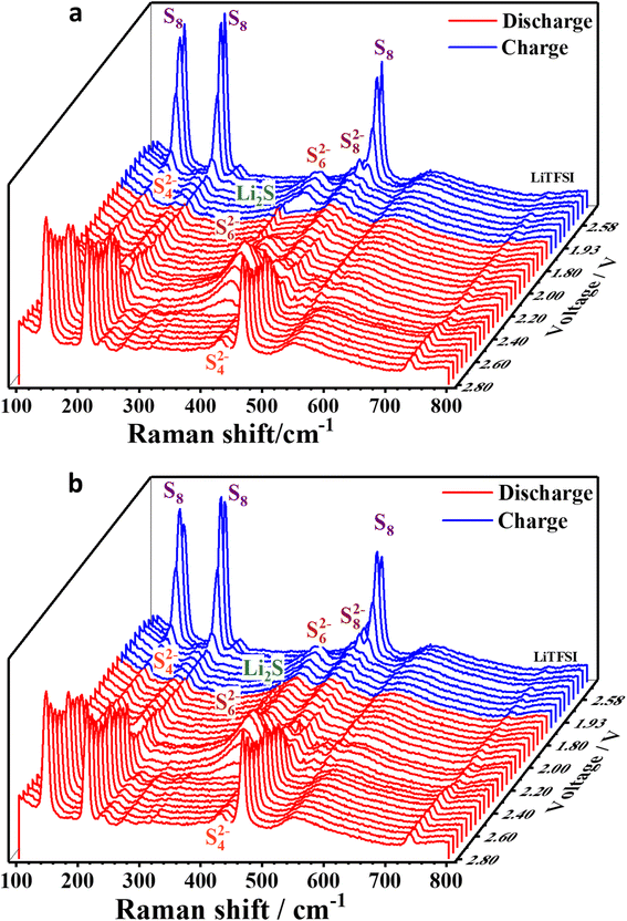 | ||
| Fig. 10 Spectra of in situ Raman scattering acquired from a Li–S battery with (a) Ni@NGC_9-modified and (b) polypropylene separator subjected to cyclic voltammetry at a scan rate of 0.1 mV s−1. | ||
4 Conclusion
This work presented the application of Ni@NGC with different amounts of metal loadings as an effective separator modification approach to enhance the performance of Li–S batteries. The efficient one-step carbonization and the following hot acidic treatment enabled the formation of a highly ordered N-doped graphitic structure with encapsulated Ni nanoparticles. The separators modified with Ni@NGC with different Ni loadings performed beneficially in all perspectives of battery electrochemistry towards stable cyclability and low polarization. The samples with a Ni loading of 9 wt% resulted in an effective ratio of surface area to the Ni content, which improved the reaction kinetics and cycling performance of Li–S cells. Batteries with Ni@NGC_9 retained 77% capacity after 200 cycles at 0.5C at a high sulfur loading of ∼4.0 mg cm−2, while the cell with a bare separator retained only 51% of its capacity. Thus, the implementation of the Ni@NGC_9 composite as a modification to the PP separator is a promising opportunity to be also explored and employed in a wider range of practical applications in various energy storage systems.Conflicts of interest
There are no conflicts to declare.Acknowledgements
This research was funded by a research grant No. AP09259764 from the Ministry of Science and Higher Education of the Republic of Kazakhstan.References
- R. Xiao, K. Chen, X. Zhang, Z. Yang, G. Hu and Z. Sun, Single-Atom Catalysts for Metal-Sulfur Batteries: Current Progress and Future Perspectives, J. Energy Chem., 2021, 54, 452–466, DOI:10.1016/j.jechem.2020.06.018.
- S. Zhao, Y. Kang, M. Liu, B. Wen, Q. Fang, Y. Tang, S. He, X. Ma, M. Liu and Y. Yan, Modulating the Electronic Structure of Nanomaterials to Enhance Polysulfides Confinement for Advanced Lithium-Sulfur Batteries, J. Mater. Chem. A, 2021, 9(35), 18927–18946, 10.1039/d1ta02741g.
- T. Ould Ely, D. Kamzabek, D. Chakraborty and M. F. Doherty, Lithium-Sulfur Batteries: State of the Art and Future Directions, ACS Appl. Energy Mater., 2018, 1(5), 1783–1814, DOI:10.1021/acsaem.7b00153.
- J. Wu, J. Chen, Y. Huang, K. Feng, J. Deng, W. Huang, Y. Wu, J. Zhong and Y. Li, Cobalt Atoms Dispersed on Hierarchical Carbon Nitride Support as the Cathode Electrocatalyst for High-Performance Lithium-Polysulfide Batteries, Sci. Bull., 2019, 64(24), 1875–1880, DOI:10.1016/j.scib.2019.08.016.
- M. Liu, Z. Yang, H. Sun, C. Lai, X. Zhao, H. Peng and T. Liu, A Hybrid Carbon Aerogel with Both Aligned and Interconnected Pores as Interlayer for High-Performance Lithium–Sulfur Batteries, Nano Res., 2016, 9(12), 3735–3746, DOI:10.1007/s12274-016-1244-1.
- T. Ould Ely, D. Kamzabek, D. Chakraborty and M. F. Doherty, Lithium–Sulfur Batteries: State of the Art and Future Directions, ACS Appl. Energy Mater., 2018, 1(5), 1783–1814, DOI:10.1021/acsaem.7b00153.
- J. He and A. Manthiram, A Review on the Status and Challenges of Electrocatalysts in Lithium-Sulfur Batteries, Energy Storage Mater., 2019, 20, 55–70, DOI:10.1016/j.ensm.2019.04.038.
- Y. Yang, Y. Zhong, Q. Shi, Z. Wang, K. Sun and H. Wang, Electrocatalysis in Lithium Sulfur Batteries under Lean Electrolyte Conditions, Angew. Chem., Int. Ed., 2018, 57(47), 15549–15552, DOI:10.1002/anie.201808311.
- H. Dunya, M. Ashuri, Z. Yue, K. Kucuk, Y. Lin, D. Alramahi, C. U. Segre and B. K. Mandal, Rational Design of Titanium Oxide-Coated Dual Core–Shell Sulfur Nanocomposite Cathode for Highly Stable Lithium–Sulfur Batteries, J. Phys. Chem. Solids, 2021, 149, 109791, DOI:10.1016/j.jpcs.2020.109791.
- Y. Zhang, X. Ge, Q. Kang, Z. Kong, Y. Wang and L. Zhan, Vanadium Oxide Nanorods Embed in Porous Graphene Aerogel as High- Efficiency Polysul Fi Detrapping-Conversion Mediator for High Performance Lithium-Sulfur Batteries, Chem. Eng. J., 2020, 393, 124570, DOI:10.1016/j.cej.2020.124570.
- H. Li, J. Wang, Y. Zhang, Y. Wang, A. Mentbayeva and Z. Bakenov, Synthesis of Carbon Coated Fe3O4 Grown on Graphene as Effective Sulfur-Host Materials for Advanced Lithium/Sulfur Battery, J. Power Sources, 2019, 437, 226901, DOI:10.1016/j.jpowsour.2019.226901.
- S. J. Kim, K. Kim, J. Park and Y. E. Sung, Role and Potential of Metal Sulfide Catalysts in Lithium-Sulfur Battery Applications, ChemCatChem, 2019, 11(10), 2373–2387, DOI:10.1002/cctc.201900184.
- Z. Jin, Z. Liang, M. Zhao, Q. Zhang, B. Liu, L. Zhang, L. Chen, L. Li and C. Wang, Rational Design of MoNi Sulfide Yolk-Shell Heterostructure Nanospheres as the Efficient Sulfur Hosts for High-Performance Lithium-Sulfur Batteries, Chem. Eng. J., 2020, 394, 124983, DOI:10.1016/j.cej.2020.124983.
- J. Zhao, D. Zhao, L. Li, L. Zhou, X. Liang, Z. Wu and Z. J. Jiang, Defect-Rich, Mesoporous Cobalt Sulfide Hexagonal Nanosheets as Superior Sulfur Hosts for High-Rate, Long-Cycle Rechargeable Lithium-Sulfur Batteries, J. Phys. Chem. C, 2020, 124(23), 12259–12268, DOI:10.1021/acs.jpcc.0c02324.
- N. Li, Z. Xu, P. Wang, Z. Zhang, B. Hong, J. Li and Y. Lai, High-Rate Lithium-Sulfur Batteries Enabled via Vanadium Nitride Nanoparticle/3D Porous Graphene through Regulating the Polysulfides Transformation, Chem. Eng. J., 2020, 398, 125432, DOI:10.1016/j.cej.2020.125432.
- M. Lei, J. G. Wang, L. Ren, D. Nan, C. Shen, K. Xie and X. Liu, Highly Lithiophilic Cobalt Nitride Nanobrush as a Stable Host for High-Performance Lithium Metal Anodes, ACS Appl. Mater. Interfaces, 2019, 11(34), 30992–30998, DOI:10.1021/acsami.9b09975.
- Z. Shen, Z. Zhang, M. Li, Y. Yuan, Y. Zhao, S. Zhang, C. Zhong, J. Zhu, J. Lu and H. Zhang, Rational Design of a Ni3N0.85Electrocatalyst to Accelerate Polysulfide Conversion in Lithium-Sulfur Batteries, ACS Nano, 2020, 14(6), 6673–6682, DOI:10.1021/acsnano.9b09371.
- D. Yang, C. Zhang, J. J. Biendicho, X. Han, Z. Liang, R. Du, M. Li, J. Li, J. Arbiol, J. Llorca, Y. Zhou, J. R. Morante and A. Cabot, ZnSe/N-Doped Carbon Nanoreactor with Multiple Adsorption Sites for Stable Lithium-Sulfur Batteries, ACS Nano, 2020, 14(11), 15492–15504, DOI:10.1021/acsnano.0c06112.
- Z. Zhang, A. H. Shao, D. G. Xiong, J. Yu, N. Koratkar and Z. Y. Yang, Efficient Polysulfide Redox Enabled by Lattice-Distorted Ni3Fe Intermetallic Electrocatalyst-Modified Separator for Lithium-Sulfur Batteries, ACS Appl. Mater. Interfaces, 2020, 12(17), 19572–19580, DOI:10.1021/acsami.0c02942.
- Y. J. Li, J. M. Fan, M. S. Zheng and Q. F. Dong, A Novel Synergistic Composite with Multi-Functional Effects for High-Performance Li-S Batteries, Energy Environ. Sci., 2016, 9(6), 1998–2004, 10.1039/c6ee00104a.
- K. Zhang, Z. Chen, R. Ning, S. Xi, W. Tang, Y. Du, C. Liu, Z. Ren, X. Chi, M. Bai, C. Shen, X. Li, X. Wang, X. Zhao, K. Leng, S. J. Pennycook, H. Li, H. Xu, K. P. Loh and K. Xie, Single-Atom Coated Separator for Robust Lithium–Sulfur Batteries, ACS Appl. Mater. Interfaces, 2019, 11(28), 25147–25154, DOI:10.1021/acsami.9b05628.
- M. Chen, X. Zhao, Y. Li, P. Zeng, H. Liu, H. Yu, M. Wu, Z. Li, D. Shao, C. Miao, G. Chen, H. Shu, Y. Pei and X. Wang, Kinetically Elevated Redox Conversion of Polysulfides of Lithium-Sulfur Battery Using a Separator Modified with Transition Metals Coordinated G-C3N4 with Carbon-Conjugated, Chem. Eng. J., 2020, 385, 123905, DOI:10.1016/j.cej.2019.123905.
- F. Wang, J. Li, J. Zhao, Y. Yang, C. Su, Y. L. Zhong, Q. H. Yang and J. Lu, Single-Atom Electrocatalysts for Lithium Sulfur Batteries: Progress, Opportunities, and Challenges, ACS Mater. Lett., 2020, 2(11), 1450–1463, DOI:10.1021/acsmaterialslett.0c00396.
- Z. Zhuang, Q. Kang, D. Wang and Y. Li, Single-Atom Catalysis Enables Long-Life, High-Energy Lithium-Sulfur Batteries, Nano Res., 2020, 13(7), 1856–1866, DOI:10.1007/s12274-020-2827-4.
- P. Xia, W. Lei, X. Wang, Z. Luo and Y. Pan, Simple Synthesis of Ni/High Porosity Biomass Carbon Composites with Enhanced Electrochemical Performance of Lithium e Sulfur Battery, J. Alloys Compd., 2020, 832, 153692, DOI:10.1016/j.jallcom.2020.153692.
- C. Li, R. Liu, Y. Xiao, F. Cao and H. Zhang, Recent Progress of Separators in Lithium-Sulfur Batteries, Energy Storage Mater., 2021, 40, 439–460, DOI:10.1016/j.ensm.2021.05.034.
- J. Cheng, Y. Wang, X. Qian and L. Jin, Separator Modification of Lithium-Sulfur Batteries Based on Ni-Zn Bimetallic MOF Derived Magnetic Porous Ni-C Composites, J. Alloys Compd., 2022, 168066, DOI:10.1016/j.jallcom.2022.168066.
- L. Zhang, D. Liu, Z. Muhammad, F. Wan, W. Xie, Y. Wang, L. Song, Z. Niu and J. Chen, Single Nickel Atoms on Nitrogen-Doped Graphene Enabling Enhanced Kinetics of Lithium–Sulfur Batteries, Adv. Mater., 2019, 31(40), 1–9, DOI:10.1002/adma.201903955.
- J. Wang, M. Chen, W. Qin and M. Zhou, A Novel Flame-Resistant Separator for High Performance Lithium-Sulfur Batteries, Adv. Mater., 2022, 6628–6635, 10.1039/d2ma00576j.
- Y. Qiu, H. Yang, B. Wen, L. Ma and Y. Lin, Facile Synthesis of Nickel/Carbon Nanotubes Hybrid Derived from Metal Organic Framework as a Lightweight, Strong and Efficient Microwave Absorber, J. Colloid Interface Sci., 2021, 590, 561–570, DOI:10.1016/j.jcis.2021.02.003.
- J. Laverde, N. C. Rosero-Navarro, A. Miura, R. Buitrago-Sierra, K. Tadanaga and D. López, Impact of Sulfur Infiltration Time and Its Content in an N-Doped Mesoporous Carbon for Application in Li-S Batteries, Batteries, 2022, 8(6), 1–17, DOI:10.3390/batteries8060058.
- B. Zhou, L. Liu, Z. Yang, X. Li, Z. Wen and L. Chen, Porous Organic Polymer Gel Derived Electrocatalysts for Efficient Oxygen Reduction, ChemElectroChem, 2019, 6(2), 485–492, DOI:10.1002/celc.201801274.
- Q. Xie, P. Zhao, S. Wu and Y. Zhang, Flexible Carbon@graphene Composite Cloth for Advanced Lithium–Sulfur Batteries and Supercapacitors with Enhanced Energy Storage Capability, J. Mater. Sci., 2017, 52(23), 13478–13489, DOI:10.1007/s10853-017-1451-5.
- J. Zhang, Z. Zhao, Z. Xia and L. Dai, A Metal-Free Bifunctional Electrocatalyst for Oxygen Reduction and Oxygen Evolution Reactions, Nat. Nanotechnol., 2015, 10(5), 444–452, DOI:10.1038/nnano.2015.48.
- P. Gao, Y. Jiang, Y. Zhu and H. Hu, Improved Cycle Performance of Nitrogen and Phosphorus Co-Doped Carbon Coatings on Lithium Nickel Cobalt Aluminum Oxide Battery Material, J. Mater. Sci., 2018, 53(13), 9662–9673, DOI:10.1007/s10853-018-2275-7.
- J. Wang, L. Jia, J. Zhong, Q. Xiao, C. Wang, K. Zang, H. Liu, H. Zheng, J. Luo, J. Yang, H. Fan, W. Duan, Y. Wu, H. Lin and Y. Zhang, Single-Atom Catalyst Boosts Electrochemical Conversion Reactions in Batteries, Energy Storage Mater., 2019, 18, 246–252, DOI:10.1016/j.ensm.2018.09.006.
- C. Zu, Y. Fu and A. Manthiram, Highly Reversible Li/Dissolved Polysulfide Batteries with Binder-Free Carbon Nanofiber Electrodes, J. Mater. Chem. A, 2013, 1(35), 10362–10367, 10.1039/c3ta11958k.
- F. Hippauf, W. Nickel, G. P. Hao, K. Schwedtmann, L. Giebeler, S. Oswald, L. Borchardt, S. Doerfler, J. J. Weigand and S. Kaskel, The Importance of Pore Size and Surface Polarity for Polysulfide Adsorption in Lithium Sulfur Batteries, Adv. Mater. Interfaces, 2016, 3(18), 1–9, DOI:10.1002/admi.201600508.
- W. Zhu, A. Paolella, C. S. Kim, D. Liu, Z. Feng, C. Gagnon, J. Trottier, A. Vijh, A. Guerfi, A. Mauger, C. M. Julien, M. Armand and K. Zaghib, Investigation of the Reaction Mechanism of Lithium Sulfur Batteries in Different Electrolyte Systems by: In Situ Raman Spectroscopy and in Situ X-Ray Diffraction, Sustain. Energy Fuels, 2017, 1(4), 737–747, 10.1039/c6se00104a.
Footnote |
| † Electronic supplementary information (ESI) available. See DOI: https://doi.org/10.1039/d3ra00891f |
| This journal is © The Royal Society of Chemistry 2023 |

