
 Open Access Article
 This Open Access Article is licensed under a Creative Commons Attribution-Non Commercial 3.0 Unported Licence
The redox mediated – scanning droplet cell system for evaluation of the solid electrolyte interphase in Li-ion batteries†
David Muñoz-Torreroab,
Carla Santana Santosc,
Enrique García-Quismondod,
Stefan Dieckhöferc,
Thomas Erichsene,
Jesús Palma d,
Wolfgang Schuhmannc and
Edgar Ventosa*ab
d,
Wolfgang Schuhmannc and
Edgar Ventosa*ab
aDepartment of Analytical Chemistry, Faculty of Science, University of Burgos, Plaza de Misael Bañuelos s/n, 09001 Burgos, Spain. E-mail: eventosa@ubu.es
bICCRAM, University of Burgos, Plaza de Misael Bañuelos s/n, 09001 Burgos, Spain
cAnalytical Chemistry, Center for Electrochemical Sciences (CES), Faculty of Chemistry and Biochemistry, Ruhr University Bochum, Universitätsstr 150, D-44780 Bochum, Germany
dElectrochemical Processes Unit, IMDEA Energy Institute, Avda. Ramón de la Sagra 3, 28935 Móstoles, Spain
eSensolytics GmbH, Mettestr. 25, D-44803 Bochum, Germany
First published on 22nd May 2023
Abstract
The so-called solid electrolyte interphase (SEI), a nanolayer formed on the negative electrode of lithium-ion batteries during the first cycles, largely influences some key performance indicators such as cycle life and specific power. The reason is due to the fact that the SEI prevents continuous electrolyte decomposition, making this protecting character extremely important. Herein, a specifically designed scanning droplet cell system (SDCS) is developed to study the protecting character of the SEI on lithium-ion battery (LIB) electrode materials. SDCS allows for automatized electrochemical measurements with improved reproducibility and time-saving experimentation. Besides the necessary adaptations for its implementation for non-aqueous batteries, a new operating mode, the so-called redox mediated-scanning droplet cell system (RM-SDCS), is established to investigate the SEI properties. By adding a redox mediator (e.g. a viologen derivative) to the electrolyte, evaluation of the protecting character of the SEI becomes accessible. Validation of the proposed methodology was performed using a model sample (Cu surface). Afterwards, RM-SDCS was employed on Si–graphite electrodes as a case study. On the one hand, the RM-SDCS shed light on the degradation mechanisms providing direct electrochemical evidence of the rupture of the SEI upon lithiation. On the other hand, the RM-SDCS was presented as an accelerated method capable of searching for electrolyte additives. The results indicate an enhancement in the protecting character of the SEI when 4 wt% of both vinyl carbonate and fluoroethylene carbonate were used simultaneously.
1. Introduction
Electrochemical energy storage devices are present in everyday life, being the power sources of choice for electric vehicles and portable electronics, amongst many other applications. The Li-ion battery (LIB) dominates the market due to its high electrochemical performances, e.g. high energy density and energy efficiency at moderate cost. Nevertheless, the demanding requirements for electro-mobility motivate researchers to keep pushing key performance indicators (KPIs) of LIBs. Some KPIs are highly influenced by the nano-layer formed on the negative electrode during the battery's first cycles, the so-called solid electrolyte interphase (SEI). The SEI is a protecting film (<100 nm thick) formed on the negative electrodes as a result of the electrolyte decomposition when low potentials are applied (<1 V vs. Li/Li+ (1 M Li+)).1–3 State-of-the-art electrolytes are not stable at such reducing conditions, so the SEI formation is a benefit since it prevents a continuous decomposition of the electrolyte and allows lithiation of the active materials, e.g. graphite or Si. Therefore, in high-performing LIBs, the SEI must exhibit two essential properties: negligible electrical conductivity and high Li-ion conductivity.2 On the one hand, a high electrical resistivity provides the protective character necessary to avoid electron transfer from the electrode surface to the electrolyte and prevent electrolyte decomposition. On the other hand, a high ionic conductivity allows fast movement of (desolvated) Li+ cations through the SEI towards the electroactive materials of the negative electrodes. Since ionic and electrical conductivities of the SEI play critical roles, these two properties have been pointed out as indicators of LIB's performance.2 The ionic conductivity of the SEI is interrogated routinely by electrochemical impedance spectroscopy (EIS),4,5 a well-established technique with high surface sensitivity that has been extensively employed to characterize electrode surfaces in LIBs. In contrast with ionic property characterization, the evaluation of the electronic conductivity did not receive as much attention, mainly due to the lack of available measuring techniques. Recently, the local protecting character of the SEI was investigated by means of measurements using scanning electrochemical microscopy (SECM).6 The SECM provided information on SEI electrochemical properties with a high lateral resolution, therefore revealing also the presence of some heterogeneities. However, analysis elucidating fast the protecting properties is still desired at the macro size. For instance, the effects of the combination of several electrolyte additives on the resulting properties of the SEI are nowadays unpredictable, and hence massive experimental work is required to achieve progress in this field.7–9Herein, a new operating mode for the scanning droplet cell system (SDCS)10–14 is developed to form and evaluate the SEI. The SDCS belongs to the family of scanning probe microscopes, where the working principle relies on the confinement of an electrochemical cell between the investigated surface (working electrode) and a hanging droplet coming out from a small aperture in the SDCS head. A counter and reference electrodes are placed inside the SDCS head. This compartment is filled with an electrolyte, which may be pumped in and out. Only the underlying surface area in contact with the droplet is polarized for the electrochemical measurements. A major advantage is that the SDCS can be programmed to carry out predefined complex experiments automatically, as well as to fill the SDC head with various electrolytes. As a result of its fully autonomous operation and its lateral resolution in the range of hundreds of micrometers, we exploited the feature of a conventional SDSC for high-throughput electrochemical analysis in the field of aqueous battery,15 and more recently implemented it for non-aqueous systems inside an Ar-filled glovebox.16 However, the SDCS had two main limitations namely that porous real-world battery electrodes could not be investigated, and the method could not provide information regarding the protecting character of the SEI. Here, we mitigate these limitations by suggesting a new design and a new operating mode of the SDCS allowing analysis of the protecting character of the SEI on commercial LIBs electrodes. The new design of the SDCS head is essential to evaluate real-world battery electrode surfaces by avoiding electrolyte leakage through the porous, and the new operating mode enables the evaluation of the protecting character of the SEI. After validation of the proposed system using a Cu surface as a model sample, the influence of several electrolyte additive mixtures on the protecting character of the SEI is investigated on commercial graphite–silicon (G–Si) electrodes.
2. Experimental
2.1. Materials
Commercial LP30 electrolyte (1 M LiPF6 in EC![[thin space (1/6-em)]](https://www.rsc.org/images/entities/char_2009.gif) :DMC 1:1 by weight) was purchased from Gotion. Vinylene carbonate (99.5%, acid < 200 ppm, H2O < 100 ppm), fluoroethylene carbonate (FEC) (>99%, acid < 200 ppm, anhydrous), dimethylcarbonate (≥99.9% anhydrous), methylviologen dichloride hydrate (98%), copper (Cu) wire (d = 1 mm, 99.9%), and lithium ribbon (99.9% trace metals) were obtained from Sigma Aldrich. Printed circuit boards with Cu (35 μm of thickness) were purchased from Bungard. The resin used for fabrication of the head of the SDSC using stereolithography was 3D Printing UV Sensitive Resin, Basic Clear was purchased to Anycubic.
:DMC 1:1 by weight) was purchased from Gotion. Vinylene carbonate (99.5%, acid < 200 ppm, H2O < 100 ppm), fluoroethylene carbonate (FEC) (>99%, acid < 200 ppm, anhydrous), dimethylcarbonate (≥99.9% anhydrous), methylviologen dichloride hydrate (98%), copper (Cu) wire (d = 1 mm, 99.9%), and lithium ribbon (99.9% trace metals) were obtained from Sigma Aldrich. Printed circuit boards with Cu (35 μm of thickness) were purchased from Bungard. The resin used for fabrication of the head of the SDSC using stereolithography was 3D Printing UV Sensitive Resin, Basic Clear was purchased to Anycubic.
2.2. Scanning droplet cell design and manufacture
The scanning droplet cell was designed using the AUTOCAD software, and the SDC head was fabricated by additive manufacturing using an Anycubic Photon SE 3D printer. More details about the SDCS are found in the ESI (Section S1†). The SDS head comprises two pieces: an upper part (body) and a lower part. These two pieces were connected inside the glovebox once the cell incorporated the Li reference and counter electrodes due to the high reactivity of Li under air and ambient water.2.3. Electrochemical measurements
Electrochemical tests were performed by using a potentiostat/galvanostat (AUTOLAB, PGSTAT302) connected to the SDC cell, which is placed inside an Ar-filled glovebox (Jacomex, H2O < 0.1 ppm and O2 < 0.1 ppm). Tests were carried out at room temperature. Li discs were used as pseudo-reference and counter electrodes (area: 0.13 cm2) for all electrochemical tests. Cu wires were used to connect the counter and reference electrodes to the external part of the SDS head. A solid electrolyte interphase (SEI) was formed on Cu or graphite–silicon (G–Si) electrodes, which were used as working electrode. The SEI formation protocol for Cu samples consisted of two steps. First, a linear sweep voltammogram (LSV) at a scan rate of 5 mV s−1 was carried out from the open circuit potential (OCP) to a certain end potential (@ in mV). In the second step, the potential was held at the selected @ potential for 30 min. The SEI formation procedure for the G–Si samples was conducted following a similar protocol: the two first steps as described for the Cu plus a third step consisting of another LSV from the potential held in the second step (SEI formation) to 1.5 V at a scan rate of 1 mV s−1. The SDC head was filled with approximately 750 μL of LP30 (1 M LiFP6 in EC:DMC 1:1 by weight) electrolyte for all SEI formation procedures. It should be noted that LP30 does not contain any SEI forming additives.
Electrochemical impedance spectroscopy (EIS) and cyclic voltammetry (CV) measurements at different scan rates in 3-electrode configuration were used to investigate the protecting character of each SEI-@. EIS measurements were carried out from 100 kHz to 100 mHz at an amplitude of 20 mV at 2.4 V vs. Li+/Li using a stabilization of 300 s whereas CV was recored from 2.2 to 2.55 V vs. Li+/Li at 20, 50, 100 and 200 mV s−1. Fittings of the EIS data were conducted using ZView® software. The electrolyte employed for evaluating the SEI properties was LP30 (1 M LiFP6 in EC:DMC 1:1 by weight) plus 10 mM of methylviologen dichloride hydrate (MVD).
Galvanostatic reduction–oxidation measurements at ±0.85 mA in the potential range of 0.05 V to 1.5 vs. Li/Li+ (1 M Li+) were applied to demonstrate the feasibility of the SDCS for evaluation of (de-)lithiation process of G–Si electrodes using LP30 as electrolyte.
3. Results and discussion
3.1. SDC head design and fabrication using additive manufacturing
SDCS is a well-established electrochemical technique that has been widely used for aqueous systems in oxygen and ambient water.10–12,15 Recently, the implementation of an SDCS inside an Ar-filled glovebox was used to investigate Li plating16 since electrolyte contamination with traces of water or oxygen leads to undesired electrochemical side reactions, i.e. hydrogen evolution or formation of LiF. More technical details for the implementation of the SDCS for non-aqueous battery research are provided in our previous work.16 However, the technique was limited to flat surfaces due to electrolyte leakage which deferred the evaluation of porous real-world battery electrodes.One approach to overcome the electrolyte leakage is exchanging the Teflon-made conical head of a conventional SDC to a more compressible material or changing the head design itself. Stereolithography (SLA) was chosen to fabricate a suitable SDC head due to the high versatility of the manufacturing technique. Fig. 1 presents a scheme of the designed SDC head comprising two pieces: the upper (body) (Fig. 1b) and the lower part or tip (Fig. 1c). While the upper piece is very similar to the design of a conventional SDCS head, the lower part was designed differently. An O-ring groove was designed to be 3D-printed at the end of the SDC tip aperture (Fig. 1c). This O-ring was essential to prevent leakage of the electrolyte on porous sample surfaces upon contact of the SDC head with the sample surface. The two parts of the SDC head were connected by the same resin used for the SDC head fabrication. The head was placed inside the glovebox during this process, once the metallic Li reference and counter electrode were integrated.
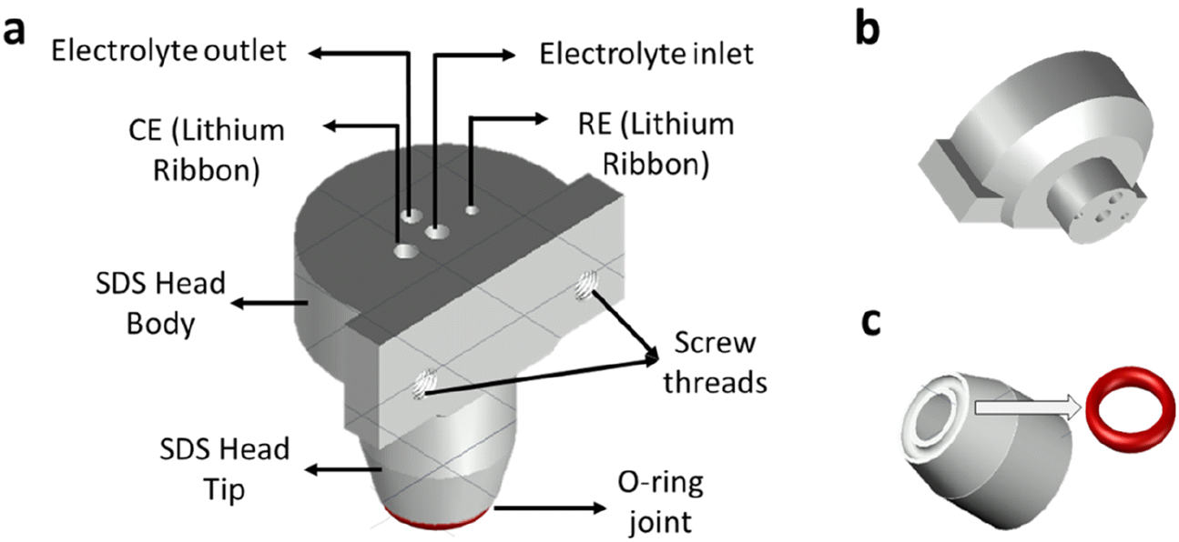 | ||
| Fig. 1 Schemes of the SDCS head: (a) upper lateral view of the cell, (b) the bottom lateral view of the upper piece or body SDC head, and (c) the lower part of SDC head, a bottom lateral view, the arrow indicates the O-ring groove. | ||
The SDC head aperture design was changed to allow the use of the O-ring, and therefore, the opening was enlarged to >1 mm. While increasing the size of the cell opening has certain advantages, it also has downsides. For a small opening size in a Teflon-made head (<500 μm), the surface tension prevents electrolyte dropping when the head moves between two areas of the sample. As the opening size increases, it becomes challenging to prevent electrolyte dropping. Thus, a strategy was adopted to pump the electrolyte out from the head after the electrochemical measurement while the SDC head was still in surface contact. For this, a new operating procedure is proposed to avoid dropping of electrolyte when using a larger cell opening, which is comprised of five steps. Firstly, the approach consists of pressing the “dried” tip of the head against the sample surface, followed by filling up the internal compartment with the electrolyte (around 750 μL) by using a pump. Then a third step, which is to conduct the local electrochemical measurement. The fourth step is to fill the head out with the electrolyte, and finally, the last step is to withdraw the SDCS head using stepper motors, moving it to another position of the sample. The new procedure enables SDCS with larger opening size i.e. larger cell area to be carried out for fully programmed and autonomous measurements for porous electrodes.
3.2. Redox-mediated (RM) operating mode for SDCS
The SEI properties are paramount for LIBs performance, including cycle life, self-discharge, capacity fading and coulombic efficiency.17 Products from the electrolyte degradation form this protecting layer when the potential of the negative electrode reaches sufficient cathodic conditions (<1 V vs. Li/Li+ (1 M Li+)). The SEI formation is mostly suppressed kinetically at a certain SEI layer thickness, and in the case of high electrical resistivity, the formed SEI prevents continuous electrolyte degradation.18,19 However, the SEI layer thickness grows gradually during cycling,20 which in turn depends on the protecting character of the formed SEI.While the ionic properties of the formed SEI are determined by electrochemical impedance spectroscopy (EIS), there is no simple way of estimating the electrical character of the film and, thus, its protecting character. Herein, we propose using an electrochemically active species (a redox mediator) that, added to the electrolyte after SEI formation, allows for evaluation of the electronic protecting character of the formed SEI. The charge transfer resistance of the redox mediator over a SEI-covered electrode is evaluated using cyclic voltammetry (qualitative analysis) and EIS (quantitative analysis). While charge transfer kinetics of the redox mediator is facilitated before the formation of the SEI, the presence of an electrically insulating film on the electrode surface should hinder the charge-transfer reaction for the redox mediator. Fig. 2 illustrates the expected behavior for the charge transfer reaction of the dissolved redox mediator depending on the properties of the SEI film: poorly protecting SEI (Fig. 2a) and in contrast an effectively protecting SEI (Fig. 2b).
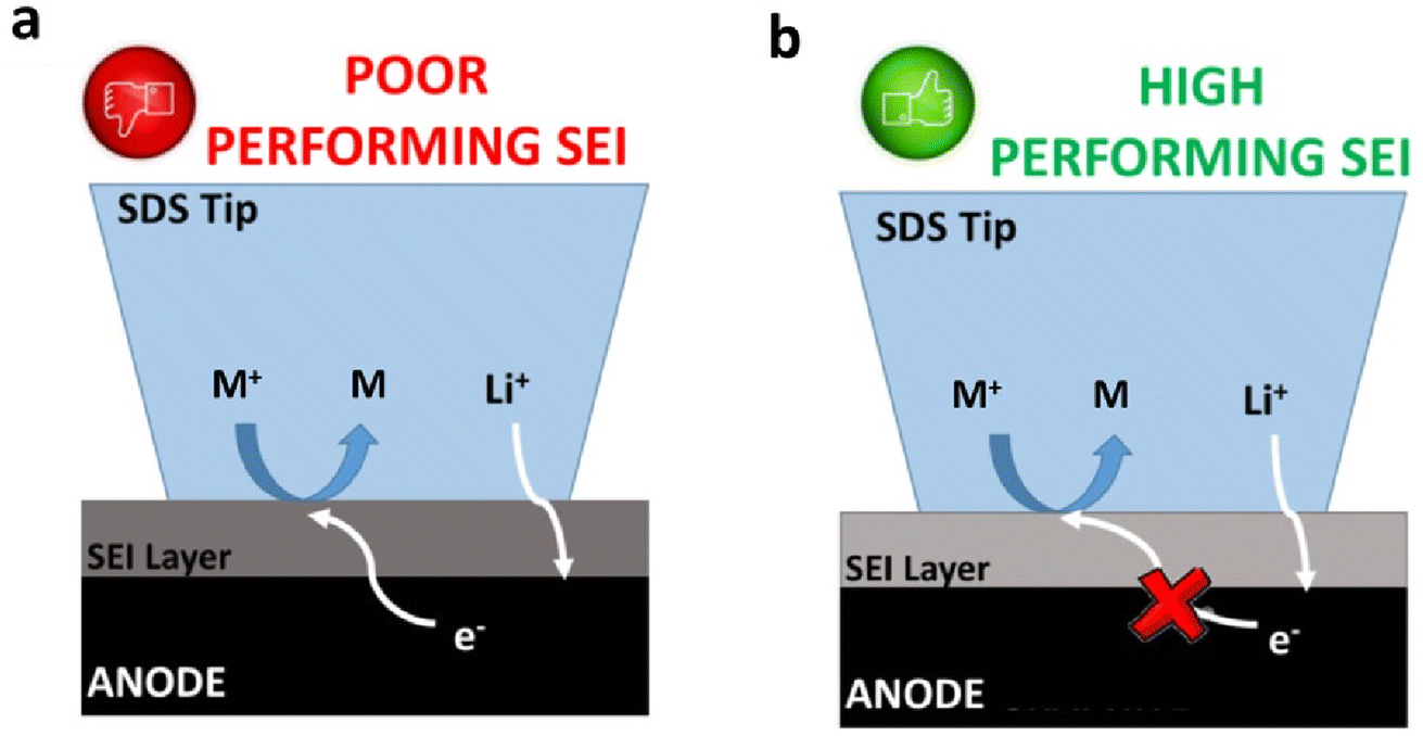 | ||
| Fig. 2 Expected behaviour for (a) poorly protecting and (b) effectively protecting SEI. | ||
In literature, the ferrocene/ferricenium (Fc/Fc+) couple has been used as a redox mediator to evaluate the SEI properties20 on various materials such as glassy carbon21 or highly oriented pyrolytic graphite (HOPG).22 However, the use of this redox couple for the evaluation of commercial negative electrodes on top of a Cu current collectors is hindered by the proximity of the redox potentials between the Fc/Fc+ and the Cu/Cu2+ (3.34 V vs. Li/Li+(1 M Li+)).23 The cyclic voltammogram registered in 10 mM Fc in 1 M LiPF6 EC:DMC electrolyte on Cu substrate illustrated this limitation (Fig. S2†).
Therefore, methylviologen dichloride (MVD) is here proposed as an alternative redox mediator, with the MVD redox potential being located at ca. 2.6 V vs. Li/Li+ (1 M Li+).24 On the one hand, this redox potential is more positive than that of the SEI formation (1 V vs. Li/Li+) and, on the other hand, it is lower than that of the Cu oxidation (<3.4 V vs. Li/Li+). Cyclic voltammograms (CV) recorded on the Cu substrate for 10 mM MVD dissolved in 1 M LiPF6 EC:DMC electrolyte confirmed the suitable redox potential and reversible redox reaction for this molecule. The resulting CV (Fig. S3†) showed a well-defined cathodic (2.35 V vs. Li/Li+) and anodic (2.45 V vs. Li/Li+) peak related to the redox processes of MVD. Moreover, a ratio value around 1 of the anodic/cathodic current peaks indicated a reversible redox process. The peak-to-peak separation obtained on Cu substrate looks larger than expected for one-electron reversible reaction, but the separation decreased when the CV was performed at glassy carbon electrode using a conventional 3-electrodes setup. This indicated that the larger separation is related to the cell. Indeed, when the potential of the CV is corrected by the iR drop (Ri obtained from the EIS measurements in Fig. S4†), the peak-to-peak separation decreased. This confirmed that the cylindrical size of the head leads to increased ionic resistance compared to a conventional setup, in which the current lines are not limited to the projected area of the electrode.
The proposed redox mediated-scanning droplet cell system (RM-SDCS) was validated using MVD to evaluate the SEI formed on the Cu substrate. Since the presence of the redox mediator during the SEI formation is not desired, a protocol including several steps was established (Fig. 3). The main difference with previous protocols is the replacement of the electrolyte (free of redox mediator) after the SEI formation by an electrolyte containing the redox mediator to evaluate its charge transfer kinetics. It should be noted that a wash step using DMC was included between two point (after SEI characterization and before the next SEI formation). The SEI was formed at different potentials, followed by investigating the properties of the resulting SEI layer. In particular, the potential for the electrolyte free of redox mediator was scanned from the open circuit potential to a final potential of 1400, 1000, 800, 600, or 200 mV. The formed SEI was named here as SEI-@, where @ is the final potential value in mV. The potential was held at that value for 30 min to complete the SEI formation. An exemplary linear sweep voltammetry during SEI formation on Cu substrate for the SEI-600 is illustrated in Fig. S4.† Observed processes were comparable to those reported during the SEI formation with similar electrolytes.6 After SEI formation, the SDCS was programmed to exchange the electrolyte with the same electrolyte containing 10 mM of MVD. CVs and EIS measurements were carried out to determine the charge transfer kinetics of the redox mediator over the formed SEI.
 | ||
| Fig. 3 Subsequent steps for the evaluation of the formation and properties of the SEI layer using RM-SDCS. | ||
Fig. 4a shows a representation of CVs recorded on the SEI-@ samples, where the current for the MVD redox process is diminished clearly as compared with the bare Cu surface (SEI-free). For a clear visualization, the current values recorded at the peaks are plotted as a function of the potential of the SEI formation (Fig. 4c). The current intensity for the redox reaction of the MVD is clearly dependent on the potential of the SEI formation as the intensity gradually decreased with a more negative potential during the SEI formation step. Interestingly, the surface reactivity changed already when the SEI was prepared at 1400 mV, indicating a passivating layer formation during the SEI formation processes around 2.2 V and 1.5 V (Fig. S4†). When the SEI is prepared at lower potentials, its protecting character seems to increase down to 200 mV. A deeper discussion requires a more quantitative evaluation and for this reason EIS measurements were recorded to determine the charge transfer resistance for the redox mediator. The Nyquist plots for the differently formed SEIs are displayed in Fig. 4b. Again, for easier visualization of the results, the charge transfer resistances for the redox mediator are plotted as a function of the potential of the SEI formation (Fig. 4d). The Nyquist plots for EIS spectra from both SEI-free and SEI-1400 showed a semicircle related to the charge transfer resistance (Re) followed by a linear increase with a slope of 45° at a lower frequency that is attributed to diffusion (Warburg element). On the other hand, Nyquist plots for SEI-1000, SEI-800, SEI-600, and SEI-200 did not show any linear region at lower frequencies. In these cases, the charge transfer resistances were high enough to cause overlapping of diffusion phenomena. Analysis of the charge transfer resistance as a function of the potential of the SEI formation (Fig. 4d) indicates that the protecting character of the SEI increases quasi-exponentially with decreasing potential of the SEI formation. The SEI film starts to possess effective protecting character at ca. 1000 mV vs. Li/Li+, but it continues increasing its protecting character with decreasing potential of the SEI formation, which is in agreement with the literature.1–3 This set of experiments also provides information about the reproducibility of the contact area for different experiments. Since the distance between WE and RE as well as the resistivity of the electrolyte remain constant, the ionic resistance obtained at the highest frequency should not change as it only depends on the surface area. The average value from the set of 5 experiments (Fig. 4) was 60.2 ± 0.7 Ω. The error of below 2% of the value confirms that the use of an O-ring together with emptying of head leads to very reproducible results.
 | ||
| Fig. 4 (a) CVs recorded at 100 mV s−1 and (b) Nyquist plots (EIS) for different SEI formation potentials and SEI-free region for Cu surface. EIS measurements were carried out from 100 kHz to 100 mHz at an amplitude of 20 mV. (c) Evolution of the reduction (jpred) and oxidation (jpox) current peaks measured at 2.32 V and 2.47 V vs. Li/Li+, respectively, as a function of the potential of the SEI formation, and (d) evolution of the charge transfer resistance calculated from the Nyquist plots as a function of the potential of the SEI formation. | ||
3.3. RM-SDCS for SEI evaluation on graphite–silicon electrodes for Li-ion batteries
After validating the EM-SDCS methodology using Cu substrate as a model electrode, a relevant case study was selected to demonstrate the potential of the presented technique. Silicon–graphite (Si–Gr) electrodes are suggested to replace the state-of-the-art graphite electrodes for the next generation of Li-ion batteries due to the abundance of Si and its high energy density. Indeed, the theoretical specific capacity of Si is 3600 mA h g−1, whereas graphite capacity is 372 mA h g−1.25 The primary drawback of Si electrodes is their poor cyclability, which is associated with forming a poor SEI layer. Repeated rupture/reconstruction of the SEI layer due to volume expansion/contraction of Si during the lithiation/delithiation process has been postulated as the main source of inefficiency.26 As a compromise, a limited amount of Si is added to graphite electrodes to increase the energy density, while issues related to the volume change on the SEI layer are minimized. The addition of 15–20 wt% of Si content into the graphite electrode results in a 15% increase in the energy density of the resulting battery.27 However, the cyclability of the resulting batteries does not yet reach the values achieved for graphite electrodes. Considerable efforts are being devoted to research for electrolyte additives, which are able to improve the properties of the SEI for Si–Gr electrodes so that cyclability is enhanced.RM-SDCS was employed for the investigation of the SEI on Si–Gr electrodes. First, the evolution of the protecting character of the SEI upon lithiation was studied in a similar approach as for the Cu model surface. It should be noted that after SEI formation, Si–Gr electrodes were de-lithiated and brought to 1.5 V vs. Li/Li+ by linear sweep voltammetry as described in the experimental section. The redox mediator was then added to the electrolyte and the charge transfer resistance of the redox mediator was evaluated by EIS to determine the protecting character of the SEI layer. By doing this, the charge transfer resistance was always evaluated at the same conditions. Before evaluating the SEI layer with RM-SDC, conventional galvanostatic measurements were carried out for Si–Gr electrodes to demonstrate that the SDCS can be used for electrochemical characterization. Fig. S5† shows the voltage profile with a typical behavior for Si–Gr electrodes.27 Fig. 5a shows the CVs recorded using RD-SDCS at different potentials for the SEI formation, and Fig. 5c summarizes the results from CVs by plotting the peak current intensity as a function of the potential of the SEI formation (SEI-free, SEI-400, SEI-200, SEI-100, SEI-50, and SEI-10). The current intensity for the redox conversion of the mediator decreased as the SEI is formed at potentials below 400 mV compared with the SEI-free surface, indicating that a passivating SEI was formed. Surprisingly, the current intensity slightly increased at a SEI-formation potential of 100 mV with respect to 400 mV, and it further increased when the potential of the SEI formation was decreased to 50 mV and 10 mV, respectively. These results with Si–Gr were in contrast to those at a Cu surface, for which the intrinsic charge transfer resistance of the SEI increases as the SEI-formation potential is decreased. Interestingly, the worsening of the protecting character of the SEI coincides with the potentials at which lithiation of Si takes place. EIS measurements (Fig. 5b) enable a more quantitative analysis of the charge transfer resistance of the redox mediator. Initially, an equivalent circuit that include Warburg element was used (see Section S5 in the ESI†). However, we realized that when the charge transfer resistance increased significantly due to the formation of an very effective SEI, the diffusion element disappeared due to the low kinetics of species (species are not depleted at the electrode surface) at the applied potential amplitude. In those cases, the Warburg element was eliminated from the equivalent circuit which resulted in an significant decrease in the error. Thus, an equivalent circuit without Warburg element was used in the following sections. For those cases in which charge transfer resistance was small enough for the appearance of an Warburg element, the 2 or 3 lowest frequencies were eliminated to obtain a fitting with a acceptable error (see ESI† for further details). In the case of the SEI formed on Cu model electrode, the representation of the charge transfer resistance as a function of the potential of the SEI formation (Fig. 5d) clearly shows that the SEI film formed below 400 mV loses its protecting character upon lithiation of Si. RM-SDCS provides electrochemical evidence concerning the lithiation of the Si–Gr electrode. The lithiation leads to mechanical degradation of the SEI due to volume changes of the Si-containing electrodes and hence higher charge-transfer kinetics for the redox conversion of the redox mediator were noticed.
 | ||
| Fig. 5 (a) CVs recorded on a Si–Gr electrode at 100 mV s−1 for different SEI-formation potentials as well as an SEI-free sample, and (b) Nyquist plots obtained from EIS measurements carried out from 100 kHz to 100 mHz with a 20 mV ac amplitude on Si–Gr electrodes for different SEI-formation potentials and an SEI-free sample. (c) Evolution of the reduction (jpred) and oxidation (jpox) current peaks measured at 2.32 V and 2.47 V vs. Li/Li+, respectively, as a function of the SEI-formation potential, and (d) evolution of the charge transfer resistance calculated from the Nyquist plots as a function of the SEI-formation potential. | ||
3.4. Search for electrolyte additives for Si–Gr electrodes using RM-SDCS as case study
Strategies for improving the cyclability of Si electrodes can be categorized into two groups, namely an “in vivo design”28 and an “in vitro design”.20 The former is based on optimising the cycling conditions with additives to change the properties of the SEI. The latter relies on forming an artificial protecting coating over the electrode, also referred to as artificial SEI. Regarding the in vivo design, a large variety of electrolyte additives have already been explored, such as vinylene carbonate (VC),26,28–30 fluoroethylene carbonate (FEC),27,28,31,32 trifluoropropylene carbonate,32 carbon dioxide,33 or lithium bis(oxalate)borate.20,34 These electrolyte additives undergo a cathodic decomposition during SEI formation leading to an improved cyclability. In particular, carbonate-based additives such as VC and FEC were reported to form stable SEI films.20,26 FEC is an appropriate additive for materials undergoing high volume changes since it seems to provide improved mechanical stability and high ionic conductivity for the SEI layer.27,35 However, FEC is constantly consumed, leading to a fast capacity fading. On the other side, VC has a relatively high reduction potential (≈1.4 V vs. Li/Li+), and its degradation products (polycarbonates) have good flexibility, creating a stable and elastic SEI film.26,28–30 Nevertheless, SEIs formed with VC usually show high ionic resistance owing to its poor Li+ diffusivity.26We employed the RM-SDCS to search for possible combinations of electrolyte additives that improve the protecting character of the SEI for commercial Si–Gr electrodes. VC and FEC were selected as electrolyte additives, and their combination was explored in 16 different electrolyte compositions (Table 1). The electrolytes were called “E”, followed by the concentration in wt. “%VC” and “%FEC” in the text to facilitate the citation. For example, “E14” electrolyte contains 1% of VC and 4% of FEC in wt.
| VC (wt%) | |||||
|---|---|---|---|---|---|
| 0 | 1 | 2 | 4 | ||
| FEC (wt%) | 0 | E00 | E10 | E20 | E40 |
| 2 | E02 | E14 | E22 | E42 | |
| 4 | E04 | E14 | E24 | E44 | |
| 6 | E06 | E16 | E26 | E46 | |
The electrochemical measurements for each electrolyte are shown in the ESI (Fig. S6 and S7†). It should be noted that E22 was not excluded due to the unreliable fitting (errors > 30%). In follow up studies (long traditional evaluation), this point should not be ruled out. Fig. 6 displays the Re obtained from EIS analysis as a function of the electrolyte composition. The main limitation of the search for electrolyte additives is the lack of predictivity, which forces researchers to devote enormous experimental efforts. For high-throughput screening of electrolyte additives, the RM-SDCS developed in this work can be of interest. Variation of the FEC concentration in the absence of VC (black bars) showed no relevant changes in the Re value compared to the control electrolyte (E00, E02, E04 and E06). On the other hand, using VC in the absence of FEC (E00, E10, E20 and E40) resulted in changes in the Re value. As for the different combinations of VC and FEC, one formulation stands out: E44. This formulation resulted in the highest charge transfer resistance. Interestingly, the addition of FEC in electrolyte containing 4 wt% VC (E40, E42, E44 and E46) resulted in poorer protecting character with respect to E40. Expect for E44, in which case the addition of FEC resulted in the opposite behavior. Thus, the SDCS used as high-throughput technique allowed us to identify an formulation of high interest. While further understanding of the origin for such behavior cannot be extracted by the RM-SDCS and it requires a deep study, the main goal of showing the feasibility of the RM-SDSC as high-throughput is achieved.
 | ||
| Fig. 6 Charge transfer resistance (Re) of the redox mediator obtained from EIS analysis for different electrolyte compositions during SEI formation. | ||
4. Conclusions
Developing advanced analytical tools is essential to keep pushing the boundaries for battery research. In this work, a new analytical technique, coined as the redox mediated-scanning droplet cell system (RM-SDCS), was established to investigate the electrically protecting properties of the SEI layer formed on the “real-world” negative electrode of Li-ion batteries. Several adaptations of conventional SDCSs were performed. Specifically, the SDCS head required a completely new design, and the 3-D printing technique stereolithography was employed to fabricate the new head design. The operating protocol was modified to enable the use of the SDCS cell head apperture in the range of millimeters without dropping the electrolyte. For this, the electrolyte was pumped out before moving the SDCS cell head. Moreover, the RM-SDCS operating mode was validated using a Cu surface as model material. As expected, the RM-SDCS showed that the electrically protecting character of the SEI, probed by the charge transfer resistance of a redox mediator dissolved in the electrolyte, improved as the potential of the SEI formation decreased.To illustrate the potential of the proposed RM-SDCS, as a relevant case study the electrically protecting character of the SEI on commercial Si–Gr electrodes was investigated. First, the RM-SDCS enable monitoring of the evolution of the electrically protecting character of the SEI upon lithiation, providing electrochemical evidence of rupture of an effective SEI layer upon lithiation likely due to the volume changes. Second, the RM-SDCS was finally used for screening electrolyte additives. A matrix of 16 electrolyte formulations that were prepared by a combination of various concentrations of vinylene carbonate (VC) and fluoroethylene carbonate (FEC) was evaluated. By this, an electrolyte formulation consisting of 4 wt% of both VC and FEC resulted in a 3-fold increase in the charge transfer resistance for the redox mediator with respect to the control electrolyte composition (without electrolyte additives).
Conflicts of interest
There are no conflicts to declare.Acknowledgements
The authors are grateful for financial support from the European Union's Horizon 2020 research and innovation programme under grant agreement NanoBat No. 861962. This work was also supported by the Regional Government of Castilla y León (Junta de Castilla y León) and by the Ministry of Science and Innovation MICIN and the European Union NextGenerationEU/PRTR and Ramón y Cajal award (RYC2018-026086-I).References
- X. Han, L. Lu, Y. Zheng, X. Feng, Z. Li, J. Li and M. Ouyang, eTransportation, 2019, 1, 100005 CrossRef
.
- S. J. An, J. Li, C. Daniel, D. Mohanty, S. Nagpure and D. L. Wood, Carbon, 2016, 105, 52–76 CrossRef CAS
- B. Scrosati and J. Garche, J. Power Sources, 2010, 195, 2419–2430 CrossRef CAS
- I. V. Krasnikova, M. A. Pogosova, A. O. Sanin and K. J. Stevenson, Chem. Mater., 2020, 32, 2232–2241 CrossRef CAS
- G. Ayalneh Tiruye, D. Muñoz-Torrero, J. Palma, M. Anderson and R. Marcilla, J. Power Sources, 2015, 279, 472–480 CrossRef CAS
- C. S. Santos, A. Botz, A. S. Bandarenka, E. Ventosa and W. Schuhmann, Angew. Chem., Int. Ed., 2022, 61(26), e202202744 CrossRef CAS PubMed
- E. R. Logan, K. L. Gering, X. Ma and J. Dahn, Electrochem. Soc. Interface, 2019, 28, 49–53 CrossRef CAS
- R. Petibon, C. P. Aiken, N. N. Sinha, J. C. Burns, H. Ye, C. M. VanElzen, G. Jain, S. Trussler and J. R. Dahn, J. Electrochem. Soc., 2013, 160, A117–A124 CrossRef CAS
- J. C. Burns, R. Petibon, K. J. Nelson, N. N. Sinha, A. Kassam, B. M. Way and J. R. Dahn, J. Electrochem. Soc., 2013, 160, A1668–A1674 CrossRef CAS
- K. A. Lill, A. W. Hassel, G. Frommeyer and M. Stratmann, Electrochim. Acta, 2005, 51, 978–983 CrossRef CAS
- J. M. Gregoire, C. Xiang, X. Liu, M. Marcin and J. Jin, Rev. Sci. Instrum., 2013, 84(2), 024102 CrossRef PubMed
- J. P. Kollender, J. Gasiorowski, N. S. Sariciftci, A. I. Mardare and A. W. Hassel, J. Phys. Chem. C, 2014, 118, 16919–16926 CrossRef CAS PubMed
- A. W. Hassel and M. M. Lohrengel, Electrochim. Acta, 1997, 42, 3327–3333 CrossRef CAS
- M. M. Lohrengel, A. Moehring and M. Pilaski, Fresenius. J. Anal. Chem., 2000, 367, 334–339 CrossRef CAS PubMed
- G. Garcia, E. Ventosa and W. Schuhmann, ACS Appl. Mater. Interfaces, 2017, 9, 18691–18698 CrossRef CAS PubMed
- S. Dieckhöfer, W. Schuhmann and E. Ventosa, ChemElectroChem, 2021, 8, 3143–3149 CrossRef
- A. Mahmoud, M. Chamas and P. E. Lippens, Electrochim. Acta, 2015, 184, 387–391 CrossRef CAS
- M. B. Pinson and M. Z. Bazant, J. Electrochem. Soc., 2013, 160, A243–A250 CrossRef CAS
- P. Verma, P. Maire and P. Novák, Electrochim. Acta, 2010, 55, 6332–6341 CrossRef CAS
- S. Kranz, T. Kranz, A. G. Jaegermann and B. Roling, J. Power Sources, 2019, 418, 138–146 CrossRef CAS
- M. Tang, S. Lu and J. Newman, J. Electrochem. Soc., 2012, 159, A1775–A1785 CrossRef CAS
- B. K. Antonopoulos, F. Maglia, F. Schmidt-Stein, J. P. Schmidt and H. E. Hoster, Batteries Supercaps, 2018, 1, 110–121 CrossRef CAS
- K. Chen and D. Xue, Applied Science and Convergence Technology, 2014, 23, 14–26 CrossRef
- L. Striepe and T. Baumgartner, Chem.–Eur. J., 2017, 23, 16924–16940 CrossRef CAS PubMed
- H. Tian, F. Xin, X. Wang, W. He and W. Han, Journal of Materiomics, 2015, 1, 153–169 CrossRef
- Y. Yang, Z. Yang, Y. Xu, Z. Li, N. Yao, J. Wang, Z. Feng, K. Wang, J. Xie and H. Zhao, J. Power Sources, 2021, 514, 230595 CrossRef CAS
- Y. Ha, D. P. Finegan, A. M. Colclasure, S. E. Trask and M. Keyser, Electrochim. Acta, 2021, 394, 139097 CrossRef CAS
- T. Jaumann, J. Balach, U. Langklotz, V. Sauchuk, M. Fritsch, A. Michaelis, V. Teltevskij, D. Mikhailova, S. Oswald, M. Klose, G. Stephani, R. Hauser, J. Eckert and L. Giebeler, Energy Storage Mater., 2017, 6, 26–35 CrossRef
- T. Taskovic, L. M. Thompson, A. Eldesoky, M. D. Lumsden and J. R. Dahn, J. Electrochem. Soc., 2021, 168, 010514 CrossRef CAS
- L. Chen, K. Wang, X. Xie and J. Xie, J. Power Sources, 2007, 174, 538–543 CrossRef CAS
- K. Schroder, J. Alvarado, T. A. Yersak, J. Li, N. Dudney, L. J. Webb, Y. S. Meng and K. J. Stevenson, Chem. Mater., 2015, 27, 5531–5542 CrossRef CAS
- K. Yao, J. P. Zheng and R. Liang, J. Power Sources, 2018, 381, 164–170 CrossRef CAS
- L. J. Krause, V. L. Chevrier, L. D. Jensen and T. Brandt, J. Electrochem. Soc., 2017, 164, A2527–A2533 CrossRef CAS
- G. Hernández, J. Mindemark, A. J. Naylor, Y. C. Chien, D. Brandell and K. Edstrom, ACS Sustainable Chem. Eng., 2020, 8, 10041–10052 CrossRef PubMed
- S. Park, S. Y. Jeong, T. K. Lee, M. W. Park, H. Y. Lim, J. Sung, J. Cho, S. K. Kwak, S. Y. Hong and N. S. Choi, Nat. Commun., 2021, 12, 1–12 CrossRef PubMed
Footnote |
| † Electronic supplementary information (ESI) available. See DOI: https://doi.org/10.1039/d3ra00631j |
| This journal is © The Royal Society of Chemistry 2023 |