
 Open Access Article
 This Open Access Article is licensed under a Creative Commons Attribution-Non Commercial 3.0 Unported Licence
Fabrication of an inverse opal structure of a hybrid metal-conducting polymer for plasmon-induced hyperthermia applications†
Quang-Hai Lea,
Thu-Uyen Trana,
Van-Tuan Dinhb,
Hoai-Nam Nguyenc,
Hong-Nam Phamc,
Xuan-Truong Nguyenc,
Luong-Lam Nguyena,
Thi-Mai-Thanh Dinha and
Van-Quynh Nguyen *a
*a
aUniversity of Science and Technology of Hanoi (USTH), Vietnam Academy Science and Technology, 18 Hoang Quoc Viet, Cau Giay, Hanoi, Vietnam. E-mail: nguyen-van.quynh@usth.edu.vn
bElectric Power University, 235 Hoang Quoc Viet, Bac Tu Liem, Hanoi, Vietnam
cInstitute of Material Sciences (IMS), Vietnam Academy Science and Technology, 18 Hoang Quoc Viet, Cau Giay, Hanoi, Vietnam
First published on 21st February 2023
Abstract
This paper describes the effective fabrication of an inverse opal (IO) structure for plasmon-induced hyperthermia applications using silver nanoparticles (AgNPs) doped in a conducting polymer of poly(3,4-ethylene dioxythiophene) (PEDOT). Indium tin oxide (ITO) substrates were firstly modified electrochemically by a layer of the inverse opal structure of PEDOT (IO-PEDOT). These as-prepared electrodes were subsequently used as working electrodes for electrodepositing AgNPs. The presence of plasmonic AgNPs doped inside a polymer network caused the hybrid of IO-PEDOT and AgNPs to generate significantly more heat than thin-film PEDOT, thin-film PEDOT/AgNPs, and IO-PEDOT under 532 nm laser irradiation. This is attributed to the synergistic effect of the large active area inverse opal structure and doped AgNPs, which exhibit more thermal energy and heat faster than the individual component structures. These findings point to a wide range of potential applications for hybrid IO-PEDOT/AgNPs in hyperthermia treatment.
1 Introduction
Nowadays, hybrid materials are well known as a type of advanced material of great interest that draws intense attention from scientists, due to their outstanding advantages that could not be seen naturally in traditional materials. The hybridization of organic and inorganic materials at the molecular level has produced a novel material class of a hybrid with numerous superior physical and chemical properties compared to that of the individual organic or inorganic material used separately.1 Typically, metal-conducting polymer-based hybrids have been considered to be an excellent material for diverse applications such as electrochromic devices,2,3 chemical sensors,4 catalysts,5 and photoelectronic,6,7 bioelectronic8 and biomedical applications.9 Delocalized π electrons on the backbone of conducting polymers incorporated with noble metallic particles (i.e. gold nanoparticles (AuNPs) and silver nanoparticles (AgNPs)) induce unique optical, electrical, and thermal properties.10 Particularly, tiny AgNPs with a size much smaller than the wavelength of light irradiation have strong coupling with light through surface plasmon resonance (SPR). This phenomenon is described as coherent collective oscillations of delocalized electrons in the conduction band of the metal when nanoparticles are excited by appropriate irradiation. As a result, an electromagnetic field is strongly enhanced at some specific areas of surrounding metal nanoparticles, named hot spots. Associated with these hot areas, two processes simultaneously occur (i) the generation of hot carriers (i.e. hot holes and hot electrons),11–13 and (ii) a local heat generation which is known as a consequence of transferring photon energy into the metal particle lattice through electron–photon interactions, along with phonon–phonon interactions with the medium surrounded.14,15 In the literature, using plasmonic nanoparticle-induced heat towards thermal therapy for cancer treatment application have been widely developed.16 This approach is similar to what has been proposed for magnetic hyperthermia when applying an alternate magnetic field.17 Hyperthermia is a type of physical cancer therapy treatment utilized in conjunction with chemotherapy to improve therapeutic efficiency and prevent drug resistance. The thermal-plasmonic effect of metal nanoparticles either in solution or on a substrate has been studied both theoretically and experimentally.18 Some recently published works have proved that the photothermal effect induced by plasmonic nanoparticles is more efficient than that of magnetic hyperthermia.19 It has a high potential for wound healing application.20 For these applications, a laser of an appropriate wavelength has been used to excite the photo-thermal plasmonic nanoparticles for generating heat. It has been demonstrated that the photo-thermal effects exhibited by Ag@AgCl NPs were able to kill E. coli and S. aureus bacteria at 99.91% and 99.97% respectively.21 The localized temperature increase may contribute to the destruction of the outmost bacterial panniculus that accelerates the penetration of free radicals more easily into bacteria which leads to its death.However, under unprotected conditions, AgNPs face some challenges for actual applications due to a high agglomeration rate of nanosized particles in their suspension. To avoid that, metal nanoparticles have been widely incorporated with various type of conjugated polymers that can both stabilize separated NPs and have easier functionalization.22,23 Among them, PEDOT as one of most superior candidates for incorporating with metal nanoparticles due to its significant properties such as high conductivity and transparent film in oxidized form and excellent stability.
The conventional approach such as the mechanical mixing of NPs suspension and monomers in the liquid phase;24 spin-coating of NPs on top of polymer layer by applying appropriate conditions25 are well-known as fast and simple technique for generating metal/polymer-based hybrids. Besides, its advantages, those techniques have some limitations in controlling the dispersion of NPs over polymer network and interaction between NPs and polymer.
This paper presents an effective fabrication of the inverse opal structure of a hybrid AgNPs/PEDOT for plasmon-induced hyperthermia application. Using a combination of nanosphere lithography and electrochemistry approach for generating inverse opal structures of CPs containing plasmonic metallic nanoparticles is more challenging than that of using of conventional approach mentioned above.26 The complexities of this approach are mainly due to some challenging steps in depositing a 3D structure PS bead template with good control of the distance between each layer, the compactness, and the exact number of the deposited layer. Thus, inverse opal structure of CPs containing metal NPs generated by this approach have been reported rarely.
In addition to controlling various factors such as evaporation rate, meniscus profile, appropriate concentration corresponding to beads size and substrate quality, the use of additional surfactants plays a critical role in achieving a high-quality bead template.27–30 However, the presence of surfactant on modified surface can be a drawback. Indeed, the surfactant covers the triangular interstitial spaces between the beads, making it difficult to deposit materials on the surface using a bottom-up approach in some cases. It addresses the necessity of developing a technique for the deposition of PS templates without the use of surfactants, ensuring uniformity and close-packed beads in 3D layer.
This work presents a modified approach for forming a 2D layer of PS, which differs from the conventional interface coating described in our previous publication.29,31 Instead of directly depositing the PS onto the water surface, we use a microscope slide as a transition step to first form a less defective 2D layer of PS. This is possible due to the hydrophilic surface of glass, which enables easy self-assembly of the PS monolayer on the glass substrate. By introducing ethanol into the PS suspension, the beads spread quickly and form a stable layer that covers the entire glass substrate. As a result, the generated 3D layer is still closely packed and uniform, even without the use of surfactants. When PS template is ready, the doping of plasmonic metal nanoparticles into the 3D inverse opal structure which combines the advantages of high active area surfaces with the assessible optical properties associated with the plasmonic nanoparticle excited, can open various useful applications, such as sensors,32 catalysts,33 and surface-enhancement in Raman spectroscopy (SERS).34 Specifically, this work focuses on the plasmon-induced hyperthermia application.
2 Materials and methods
2.1 Materials
All chemicals such as silver(I) nitrate (AgNO3, ≥99.5%), lithium perchlorate (LiClO4); potassium nitric (KNO3, ≥99%), ammonia solution (NH3, 25%), 3,4-ethylene dioxythiophene (EDOT), sodium dodecyl sulfate (SDS), hydrogen peroxide 30% (H2O2), sulphuric acid (H2SO4, 95–98%), sodium hydroxide (NaOH); tetrahydrofuran (THF) were purchased from Sigma-Aldrich, Singapore. Purchased chemicals were used directly as received without any further purification. Indium-tin oxides (ITO) substrates were supplied by LUMTEC, Taiwan. The monodisperse carboxylate-modified PS spheres have a diameter of 500 nm and 10 wt% solution in water, were purchased from Sigma-Aldrich.2.2 Methods
3 Results and discussion
3.1 Characterization of multilayer of PS layer deposited
There are several reasons for interest in the self-assembly of PS beads to make a 2D or 3D template for generating various nanostructured surfaces. Finding an optimal route for making a PS template with high reproducibility, therefore, is an essential part of fabrication. Many techniques based on controlling the evaporation rate of solvent in colloidal solution with the presence of surfactant have been developed by our research group to produce a good 2D template of assembled PS beads.12,28–30 This work presents a different experimental protocol to obtain 3D layers with high-oriented PS beads in a large area on the substrate without using any surfactant.SEM image (Fig. 1a) and corresponding line profile across 5 neighbouring beads (Fig. 1b) and AFM image (Fig. 1c) show the top-view observation of 500 nm diameter spheres deposited on ITO substrates. Despite some defections observed, the organization of spheres is well-ordered and hexagonally close-packed at the top which is adequate for the electrochemical deposition of PEDOT subsequently. Moreover, thanks to such defections (as seen across line profile 2 and 3, Fig. 1a) some PS beads underneath the top layer were revealed. The line profile crossing the defect has been extracted (inset Fig. 1b and inset Fig. 1c). The cross-section profile of few adjacent beads not only shows a distance between neighboured peaks of 500 nm corresponding to the diameter of PS used but also illustrates the profile of PS bead underneath layer. This result proved the PS beads have been deposited with a multilayer on the ITO surface. However, the different number of PS layers deposited was not fully demonstrated.
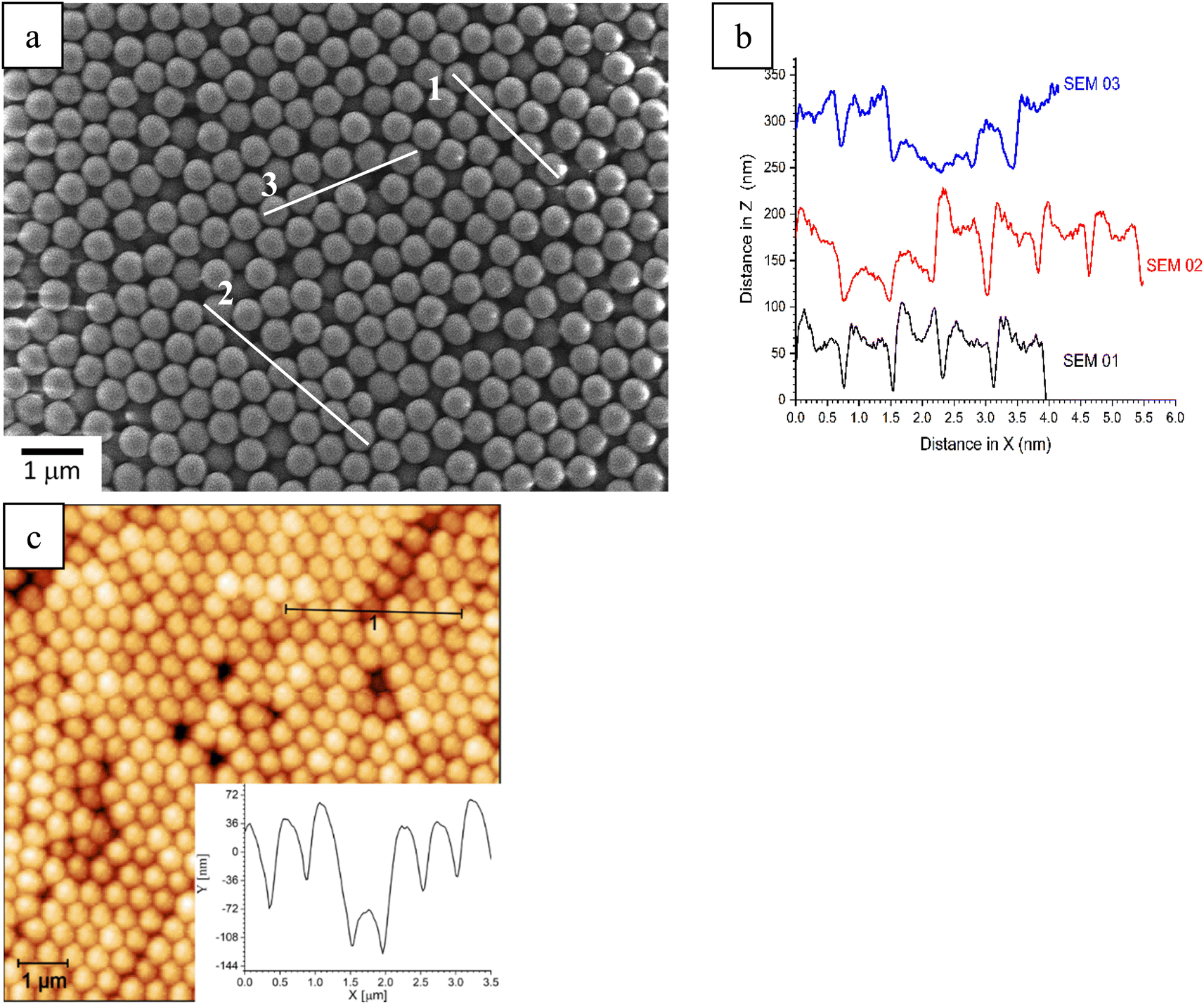 | ||
| Fig. 1 (a) SEM, (b) three cross-section profile of adjacent beads; (c) AFM image of 500 nm spheres multilayer deposited on the ITO surface via interfaced coating without using any surfactant. | ||
Fig. 2 shows the transmittance spectra of the different number of PS layers with a size of 500 nm in diameter by UV-Vis characterization. It clearly shows that the transmittance decreases as the number of PS layers deposited increases. All transmittance spectra have a similar shape and peak position which implies a similar crystal quality for all samples prepared. However, each curve shows a different transmittance percentage which depends on the number of the PS layer deposited. During the characterization, at the deposition of the first monolayer, light can penetrate through the PS beads and the empty voids formed between these adjacent beads. When the second PS layer is deposited, it covers these spaces and the transmitted light intensity is a function of the number of layers deposited. As a consequence, except for the transfer of the second layer onto the first (as evidenced by the decrease in the black curve to the red curve), the transmittance decreases by a constant percentage with each subsequent layer deposited (seen in the depletion on the red curve to the blue curve, and on the blue curve to the green one). Obviously, the thicker layer, the lower transmittance is and vice versa the thinner layer corresponds to the higher transmittance. This result is in good agreement with the published articles35,36 in terms of the transmission of PS with different sizes. Similar results have been demonstrated with the size of PS 1 μm opal structure as shown in ESI 3.†
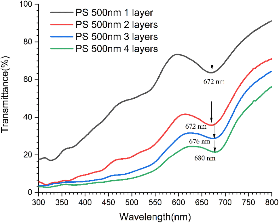 | ||
| Fig. 2 The transmittance spectra of multilayer PS 500 nm by UV-Vis characterization. | ||
3.2 Generation of inversed opal PEDOT film on ITO surface
Using the same procedure published in our previous paper,29 the electro-polymerization of EDOT occurs in the voids formed between PS deposited. Fig. SI 4† shows that the electrode potential is stable at 1.1 V during a whole deposition process. It demonstrates that EDOT radicals are homogeneous in a solution, allowing PEDOT to grow well through the multi-layer of PS without any interferences caused by a steric hindrance of the 3D PS template. After dissolving PS in tetrahydrofuran (THF) for 24 hours, an inversed opal structure of PEDOT was generated as shown in Fig. 3.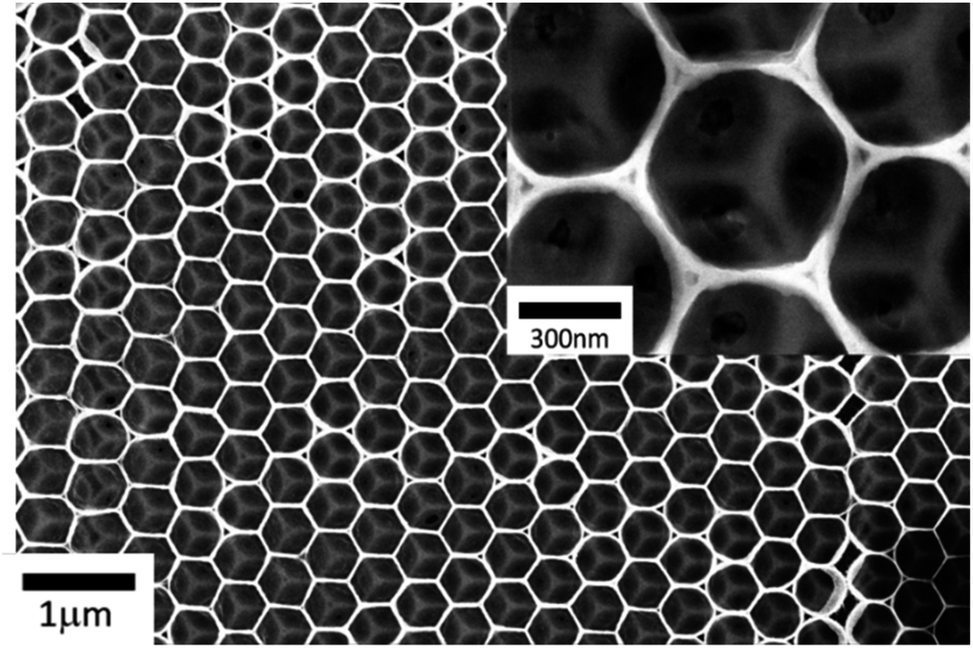 | ||
| Fig. 3 SEM image of inversed opal structure of PEDOT (IO-PEDOT). | ||
Fig. 3 presents an SEM image of the IO-PEDOT at different magnifications. It reveals a periodic structure consisting of a regular network of connected macro pores along with ordered mesopores corresponding to hindered volume by PS beads and where they touched, respectively. The pore size of the PEDOT structure is controlled by the size of the PS bead used. Fig. SI 3† presents SEM images of PEDOT inversed opal (IOs) generated by using different PS beads with a diameter of 500 nm (Fig. SI 5a†) and 1000 nm (Fig. SI 5b†) and its corresponding pore size distribution analyses seen in Fig. SI 5c and d† respectively. It illustrates that the 500 nm PS spheres exhibited a mean IO-PEDOT pore size of 435 nm, while the used PS bead of 1000 nm generated a mean IO-PEDOT pore size of 950 nm. It suggests a typical IO-PEDOT pore size that is approximate ∼90% of the PS sphere diameter used. This result clearly demonstrates the successful generation of inversed opal structure of PEDOT with different pore sizes.
3.3 Electrodeposition of AgNPs on different modified electrodes
Fig. 4 compares the CV curve for electrodepositing AgNPs on different working electrodes (i.e. AgNPs/ITO (black curve); AgNPs/PEDOT-film (blue curve), and AgNPs/PEDOT/PS (red curve)) in the window potential from −0.8 to 0.2 V (vs. Ag/AgCl). All deposition curves exhibit a strong cathodic peak at different potentials of −0.35 V; −0.55 V and −0.65 V for ITO (black), ITO/PEDOT (blue), and ITO/PEDOT/PS (red) respectively. These cathodic peaks are attributed to the reduction of Ag+ ions diffusing from a bulk solution to be deposited as AgNPs on an electrode surface.12 It obviously illustrates that AgNPs were electrode deposited on ITO bare at less negative potential compared to PEDOT-modified ITO. The presence of PS on the PEDOT-modified electrode gives a shift potential deposition even more negative (i.e. from −0.55 V to −0.65 V). It is explained by the steric effect of PS deposited on the surface, which may reduce Ag+ diffusion toward the electrode for reduction. Interestingly, the current intensity recorded on the working electrode of ITO/PEDOT and ITO/PEDOT/PS is larger than that of bare ITO. These findings reflect the fact that the existence of PEDOT increases the overall active area of the working electrode. | ||
| Fig. 4 Comparison of the electrodeposition of AgNPs on different modified electrodes. | ||
Fig. 5 presents the Tafel polarization plots of the deposition of AgNPs on different modified electrodes: ITO/AgNPs (black curve), ITO/PEDOT/AgNPs (blue curve), and ITO/PEDOT/PS/AgNPs (red curve). The results show that the corrosion potential (Ecorr) value of ITO/PEDOT/AgNPs (−0.56 V) is a significant shift towards the negative potential compared to that of the substrate ITO/AgNPs (−0.16 V). On the other hand, there was only a small shift in the corrosion potential observed when comparing ITO/PEDOT/AgNPs (−0.56 V, blue curve) and ITO/PEDOT/PS/AgNPs (−0.58 V, red curve). Besides, the corrosion current density (icorr) value are evaluated to be 0.317, 0.501 and 0.525 mA cm−2 for ITO/AgNPs, ITO/PEDOT/PS/AgNPs and ITO/PEDOT/AgNPs respectively. This indicates that the presence of PEDOT on the substrate enhances charge accumulation due to its high conductivity as a conducting polymer. A higher conductivity corresponds to a higher electron transfer rate, which is associated with a superior electrocatalytic performance to corrode AgNPs at the electrode/electrolyte interface. Meanwhile, the presence of PS as a 3D insulating template does not have a strong influence on the values of Ecorr and icorr due to its high porosity which does not prevent electron transfer across the insulating layer of PS. This explains the ease of depositing PEDOT and AgNPs on the substrate even using 3D layer of PS as template.
 | ||
| Fig. 5 Tafel plots of deposition curves of AgNPs on different modified electrodes. | ||
Fig. 6 shows SEM images of the ITO/PS/PEDOT/AgNP substrate before (Fig. 6a) and after (Fig. 6b) removal of PS bead away.
 | ||
| Fig. 6 SEM images of (a) ITO/PS/PEDOT/AgNP, (b) a hybrid nanostructuration of inversed opal PEDOT–AgNPs. | ||
Fig. 6a proves that tiny nanoparticles can easily be electrochemically deposited on ITO/PS/PEDOT substrate. Despite the observation of some defections, the well-ordered hexagonally nanostructuration of hybrid nanoparticles-decorated PEDOT was generated. Fig. 6b clearly demonstrated that the nanoparticles are mainly deposited on the walls of the pores of nanostructuration and silver nanoparticles are randomly distributed and their size is still not uniform. To confirm the existence of silver nanoparticle on the surface, the energy-dispersive X-ray spectroscopy (EDX) characterization of these nanoparticle-covered polymer surfaces have been carried out. Fig. SI 6† with elemental investigation reveals the existence of AgNPs deposited onto PEDOT polymers. Interestingly, Fig. SI 6c† presents cross-sectional SEM images of a hybrid thin film at different magnifications, which clearly demonstrate that AgNPs were not only deposited on the surface, but also embedded inside the polymer film. This obtained results fully proves the successful fabrication of an inverse opal PEDOT/Ag on the flat substrate.
3.4 The plasmon-induced heating effect
After the successful generation of an inverse opal PEDOT/Ag, such nanostructured hybrid material has been applied for investigating plasmon-induced heat.Fig. 7 shows the heating effect of different deposited materials on the ITO electrode. It is shown that for all samples irradiated by a source laser of 532 nm, the increasing heating effect is different with diverse samples. It is obvious that the IO-PEDOT structure sample (green curve) generated more heat than the PEDOT film (red curve), but the time period to reach a saturated temperature is similar, within 200 s, it reached 34 °C and 30 °C, respectively. A similar phenomenon also is observed in the case of PEDOT/AgNPs (blue curve) and IO-PEDOT/AgNPs (black curve). It fully proves that the inverse opal structure strongly contributes to higher heating efficiency.
 | ||
| Fig. 7 The heating effect curves of modified ITO electrode characterized by single-frequency visible lasers 532 nm. | ||
The result of the PEDOT and IO-PEDOT doping AgNPs template also showed a larger increase of temperature than the PEDOT and IO-PEDOT without AgNPs, but it took much more time to reach a saturated temperature, IO-PEDOT rise gradually from 27 °C to 34 °C within 200 s, while there has a substantial increase of IO-PEDOT/AgNPs from 27 °C to 39 °C within 600 s. An increment of 9 °C was obtained when comparing heat generated on IO-PEDOT/Ag with that of purely PEDOT film. It demonstrated that doped AgNPs into the materials will also greatly impact the heat generated. It is well known that AgNPs with a size much small than laser wavelength irradiated (i.e. 532 nm), the AgNPs exhibited a surface plasmon resonance property in which maximum absorption of light at a tiny confined area (i.e. hotspot), which can be considered as a heating source to heat up the surrounding environment. As a consequence, the temperate raised locally nearby the AgNPs surface.
The obtained result demonstrated that the combined effect of the inverse opal structure with a large active area, a huge material volume, and the doping of silver nanoparticles generated more thermal energy and heated faster than the individual simple structure. It can be explained by the synergic effect of the two factors including AgNPs and active surface area. These results show high potential for hyperthermia application for antibacterial through the heat generated.
4 Conclusion
In this paper, a novel experimental protocol for creating 3D layers of high-compact PS beads on a large substrate area without using any surfactant was reported. Interestingly, the as-prepared 3D layers of PS were used as a template for generating successfully an inverse opal structure of hybrid material based on AgNPs and PEDOT by an effective bottom-up approach using electrochemistry combined with the nanosphere lithography technique. Under the irradiation of laser 532 nm the fabricated hybrid of IO-PEDOT/AgNPs exhibited a local temperature increment of 9 °C in comparison with that recorded on thin-film PEDOT. These obtained results draw many potential applications of hybrid IO-PEDOT/AgNPs in the field of hyperthermia treatment for cancer or antibacterial application.Author contributions
Q.-H. Le; T.-U. Tran; V.-T. Dinh: investigation, experiment, methodology, formal analysis. X.-T. Nguyen; H.-N. Nguyen; H.-N. Pham; L.-L. Nguyen; T.-M.-T. Dinh: writing – original draft, editing manuscript. V.-Q. Nguyen: conceptualization, investigation, writing, revising and submitting.Conflicts of interest
There are no conflicts to declare.Acknowledgements
This work was funded by Vietnam Academy of Science and Technology (VAST) under grant number DL0000.06/20-22.References
- Z. Cui, C. Coletta, T. Bahry, J.-L. Marignier, J.-M. Guigner, M. Gervais, S. Baiz, F. Goubard and S. Remita, Mater. Chem. Front., 2017, 1, 879–892 RSC.
- M. Li, L. Yang and Y. Wang, Giant, 2023, 13, 100137 CrossRef CAS.
- W. Zhang, X. Chen, G. Zhang, S. Wang, S. Zhu, X. Wu, Y. Wang, Q. Wang and C. Hu, Sol. Energy Mater. Sol. Cells, 2019, 200, 109919 CrossRef CAS.
- Z. Liu, B. Lu, Y. Gao, T. Yang, R. Yue, J. Xu and L. Gao, RSC Adv., 2016, 6, 89157–89166 RSC.
- R. Poupart, D. Grande, B. Carbonnier and B. Le Droumaguet, Prog. Polym. Sci., 2019, 96, 21–42 CrossRef CAS.
- R. Tel-Vered, J. S. Kahn and I. Willner, Small, 2016, 12, 51–75 CrossRef CAS PubMed.
- V. Kaltenhauser, T. Rath, M. Edler, A. Reichmann and G. Trimmel, RSC Adv., 2013, 3, 18643–18650 RSC.
- N. A. A. Shahrim, Z. Ahmad, A. Wong Azman, Y. Fachmi Buys and N. Sarifuddin, Mater. Adv., 2021, 2, 7118–7138 RSC.
- Z.-T. Lin, J. Gu, H. Wang, A. Wu, J. Sun, S. Chen, Y. Li, Y. Kong, M. X. Wu and T. Wu, ACS Sens., 2021, 6, 2147–2157 CrossRef CAS PubMed.
- S. Sarkar and N. Levi-Polyachenko, Adv. Drug Delivery Rev., 2020, 163–164, 40–64 CrossRef CAS PubMed.
- V.-Q. Nguyen, Y. Ai, P. Martin and J.-C. Lacroix, ACS Omega, 2017, 2, 1947–1955 CrossRef CAS PubMed.
- N. M. Thu, D. Van Tuan, D. T. T. Ngan, P. H. Nam and N. Van Quynh, Vietnam J. Chem., 2022, 60, 597–605 CAS.
- G. Liu, K. Du, J. Xu, G. Chen, M. Gu, C. Yang, K. Wang and H. Jakobsen, J. Mater. Chem. A, 2017, 5, 4233–4253 RSC.
- L.-L. Nguyen, Q.-H. Le, V.-N. Pham, M. Bastide, S. Gam-Derouich, V.-Q. Nguyen and J.-C. Lacroix, Nanomaterials, 2021, 11, 1957 CrossRef CAS PubMed.
- G. Baffou, P. Berto, E. Bermúdez Ureña, R. Quidant, S. Monneret, J. Polleux and H. Rigneault, ACS Nano, 2013, 7, 6478–6488 CrossRef CAS PubMed.
- X. Huang and M. A. El-Sayed, Alexandria J. Med., 2011, 47, 1–9 CrossRef.
- D.-H. Kim, S.-H. Lee, K.-N. Kim, K.-M. Kim, I.-B. Shim and Y.-K. Lee, J. Magn. Magn. Mater., 2005, 293, 320–327 CrossRef CAS.
- H. H. Richardson, M. T. Carlson, P. J. Tandler, P. Hernandez and A. O. Govorov, Nano Lett., 2009, 9, 1139–1146 CrossRef CAS PubMed.
- S. Nemec, S. Kralj, C. Wilhelm, A. Abou-Hassan, M.-P. Rols and J. Kolosnjaj-Tabi, Appl. Sci., 2020, 10, 7322 CrossRef CAS.
- J. Sun, L. Song, Y. Fan, L. Tian, S. Luan, S. Niu, L. Ren, W. Ming and J. Zhao, ACS Appl. Mater. Interfaces, 2019, 11, 26581–26589 CrossRef CAS PubMed.
- C. Mao, Y. Xiang, X. Liu, Y. Zheng, K. W. K. Yeung, Z. Cui, X. Yang, Z. Li, Y. Liang, S. Zhu and S. Wu, ACS Appl. Mater. Interfaces, 2019, 11, 17902–17914 CrossRef CAS PubMed.
- A. M. El-Toni, M. A. Habila, J. P. Labis, Z. A. ALOthman, M. Alhoshan, A. A. Elzatahry and F. Zhang, Nanoscale, 2016, 8, 2510–2531 RSC.
- C. Hanske, M. N. Sanz-Ortiz and L. M. Liz-Marzán, Colloidal Synth. Plasmonic Nanomet., 2020, 755–820 CAS.
- M. Mumtaz, E. Cloutet, C. Labrugère, G. Hadziioannou and H. Cramail, Polym. Chem., 2013, 4, 615–622 RSC.
- D. Singh, R. Tao and G. Lubineau, npj Flexible Electron., 2019, 3, 10 CrossRef.
- Y. Vasquez, M. Kolle, L. Mishchenko, B. D. Hatton and J. Aizenberg, ACS Photonics, 2014, 1, 53–60 CrossRef CAS.
- D.-H.-N. Nguyen, Q.-H. Le, T.-L. Nguyen, V.-T. Dinh, H.-N. Nguyen, H.-N. Pham, T.-A. Nguyen, L.-L. Nguyen, T.-M.-T. Dinh and V.-Q. Nguyen, J. Electroanal. Chem., 2022, 921, 116709 CrossRef CAS.
- V.-Q. Nguyen, D.-H.-N. Nguyen, B.-M. Nguyen, T.-M.-T. Dinh and J.-C. Lacroix, Electrochem. Commun., 2019, 102, 63–66 CrossRef CAS.
- V.-Q. Nguyen, D. Schaming, P. Martin and J.-C. Lacroix, ACS Appl. Mater. Interfaces, 2015, 7, 21673–21681 CrossRef CAS PubMed.
- V.-Q. Nguyen, D. Schaming, D. L. Tran and J.-C. Lacroix, ChemElectroChem, 2016, 3, 2264–2269 CrossRef CAS.
- V.-Q. Nguyen, D. Schaming, P. Martin and J.-C. Lacroix, Langmuir, 2019, 35, 15071–15077 CrossRef CAS PubMed.
- D. Shi, X. Zhang, Z. Yang, S. Liu and M. Chen, RSC Adv., 2016, 6, 85885–85890 RSC.
- H. Li, J. F. Wang, G. Vienneau, G. B. Zhu, X. G. Wang, J. Robichaud, B.-L. Su and Y. Djaoued, RSC Adv., 2017, 7, 46406–46413 RSC.
- Z. Cai, Y. Yan, L. Liu, S. Lin and X. Hu, RSC Adv., 2017, 7, 55851–55858 RSC.
- S. H. Park, O.-H. Kim, J. S. Kang, K. J. Lee, J.-W. Choi, Y.-H. Cho and Y.-E. Sung, Electrochim. Acta, 2014, 137, 661–667 CrossRef CAS.
- J. R. Oh, J. H. Moon, S. Yoon, C. R. Park and Y. R. Do, J. Mater. Chem., 2011, 21, 14167–14172 RSC.
Footnote |
| † Electronic supplementary information (ESI) available. See DOI: https://doi.org/10.1039/d3ra00342f |
| This journal is © The Royal Society of Chemistry 2023 |