
 Open Access Article
 This Open Access Article is licensed under a Creative Commons Attribution-Non Commercial 3.0 Unported Licence
A hybrid piezoelectric and triboelectric nanogenerator with lead-free BZT–BCT/PDMS composite and PVA film for scavenging mechanical energy†
S. R. Gopala,
T. S. Velayutham *a,
W. C. Ganb,
J. Y. Cheonga and
A. E. Soha
*a,
W. C. Ganb,
J. Y. Cheonga and
A. E. Soha
aLow Dimensional Materials Research Centre, Department of Physics, Faculty of Science, Universiti Malaya, 50603 Kuala Lumpur, Malaysia. E-mail: t_selvi@um.edu.my
bSchool of Energy and Chemical Engineering, Xiamen University Malaysia, Jalan Sunsuria, Bandar Sunsuria, Selangor Darul Ehsan 43900, Malaysia
First published on 9th March 2023
Abstract
A hybrid piezo/triboelectric nanogenerator (H/P-TENG) is designed for mechanical energy harvesting using polymer ceramic composite films; polydimethylsiloxane/Ba(Zr0.2Ti0.8)O3–0.5(Ba0.7Ca0.3)TiO3 (PDMS/BZT–BCT) and polyvinyl alcohol (PVA). A lead-free BZT–BCT piezoelectric ceramic was prepared via solid-state method and blended into PDMS to form a series of polymer-ceramic composite films, ranging from 5% to 30% by weight. The films were forward/reverse poled with corona poling and their electrical properties were compared to non-poled samples. The H/P-TENG constructed with forward-poled 15 wt% BZT–BCT in PDMS achieved the highest open-circuit voltage, Voc of 127 V, short-circuit current density, Jsc of 67 mA m−2, short-circuit charge density, Qsc of 118 μC m−2, and peak power density of 7.5 W m−2, an increase of 190% over pristine PDMS-based TENG. It was discovered that incorporating BZT–BCT into the PDMS matrix improved the triboelectric properties of PDMS. The overlapping electron cloud (OEC) model was used to explain the enhancement and the effect of poling direction of the PDMS/BZT–BCT composite used in H/P-TENG, providing fundamental knowledge of the influence of piezoelectric polarisation on contact electrification.
Introduction
In the last decade, the internet of things (IoT) has given rise to a significant increase in the use of smart devices and sensors.1–3 Understandably, the need for a clean, safe power source for these devices and sensors has risen as well.4,5 Mechanical energy, being one of the most widely available energies in the environment, provides a more viable means to produce self-powered devices. In that context, triboelectric nanogenerators (TENG) stand out as a promising option among the various conceivable alternatives.6–8 TENGs transform mechanical energy into electrical energy by utilising the triboelectric effect.9,10 Contact electrification and electrostatic induction play an important role in the operation of the TENG,11,12 therefore any modifications and improvements to the TENG would revolve around these two phenomena. Despite its high open-circuit voltage output, TENG has a high internal resistance and a low short-circuit current output, resulting in a poorer and unstable power density.13–15 On the other hand, piezoelectric nanogenerators (PENG) are able to convert mechanical energy into electrical energy via the piezoelectric effect.16–18 In comparison to TENG, PENG typically has higher short-circuit current but lower open-circuit voltage. TENG and PENG are both capable of converting irregular, low frequency, and distributed mechanical energy into electrical energy. Combining the benefits of PENG and TENG, a hybrid piezoelectric–triboelectric nanogenerator (H/P-TENG) can be expected to create impressive open-circuit voltage and short-circuit current at the same time, thus it is worth exploring.19In recent years, several H/P-TENGs have been produced and demonstrated to have promising features.20 The type of materials utilised for the triboelectric layers and the number of terminals are important aspects to consider when developing H/P-TENG.21–25 PDMS is commonly used in TENG systems, as it is a flexible, inexpensive material that has high tribo-negativity.26,27 Its tendency to attract electrons when in contact with a tribo-positive surface makes it very desirable as TENGs. Conversely, PVA film has high tribo-positivity, allowing it to lose electrons when coming into contact with tribo-negative materials.28,29 This is a perfect combination of materials for a TENG device, but the energy output is still minimal. Prior research are centered on merging TENG and PENG in either series or parallel modes, or making use of organic piezoelectric materials such as PVDF and its copolymer as the tribo- and piezo-materials simultaneously.28 When compared to organic counterparts, the piezoelectric characteristics of inorganic piezoelectric materials are significantly superior. The drawback is that there is a restricted amount of flexibility. One further possibility for getting over the aforementioned restriction is to use interconnected ferroelectric films i.e., lead zirconate titanate (PZT)30 or BiFeO3 (ref. 31) on flexible glass fibre fabric, ZnO nanorod/PVDF-PTFE,32,33 ZnO nanowire/parylene C,34 BTO/PDMS,35,36 PDMS/carbon coated BT37 and etc.
Ba(Zr0.2Ti0.8)O3–0.5(Ba0.7Ca0.3)TiO3 (BZT–BCT) is a lead-free binary piezoelectric ceramic which has gained popularity due to its unique characteristics such as high dielectric constant ∼2400, high piezoelectric constant ∼471 pC N−1 and high polarizability ∼103 mC m−2.38,39 BZT–BCT has been utilised as the piezoelectric material in numerous PENG devices,40,41 but it has not been utilised in any notable TENG-based systems. In this study, we mixed BZT–BCT ceramic powder into the PDMS matrix to form a PDMS/BZT–BCT composite film. The high piezoelectric and dielectric properties of the BZT–BCT ceramic powder is hypothesized to enhance the charge concentration in PDMS due to synergistic effect of piezoelectricity and triboelectricity, thus enhancing the overall electrical output of the H/P-TENG. We studied the wt% and poling direction of the ceramic filler to determine the optimized polymer ceramic composite film that leads to the maximum enhancement to the power density output of the H/P-TENG. By means of its synergistic design, this hybrid generator may compensate for the shortcomings of each transducing mechanism, allowing it to be employed as energy supply units in a wide range of applications.
Methodology
BZT–BCT ceramic powder
The BZT–BCT ceramic is produced using high purity BaCO3 (>99%), ZrO2 (99.95%), CaCO3 (>99%) and TiO2 (99.95%) powders. The BZT and BCT are stoichiometrically mixed, ball milled separately in ethanol for 24 hours and calcined at 1200 °C for 2 hours. Next, the BZT and BCT powders are ball milled together in a BZT![[thin space (1/6-em)]](https://www.rsc.org/images/entities/char_2009.gif) :BCT ratio of 2:1 to produce BaZr0.2Ti0.8O3–0.5[Ba0.7Ca0.3TiO3] (BZT–0.5BCT). The BZT–BCT ceramic powder is sieved through a 70 microns mesh sieve and pelletized using uniaxial compression. The ceramic pellet is sintered for two hours at 1300 °C. Crystalline phases of the sintered ceramic are investigated by X-ray diffraction XRD (Empyrean X-ray Diffractometer) and the analysis is shown in Fig. S1 (see ESI†).
:BCT ratio of 2:1 to produce BaZr0.2Ti0.8O3–0.5[Ba0.7Ca0.3TiO3] (BZT–0.5BCT). The BZT–BCT ceramic powder is sieved through a 70 microns mesh sieve and pelletized using uniaxial compression. The ceramic pellet is sintered for two hours at 1300 °C. Crystalline phases of the sintered ceramic are investigated by X-ray diffraction XRD (Empyrean X-ray Diffractometer) and the analysis is shown in Fig. S1 (see ESI†).
Polydimethylsiloxane (PDMS)-BZT–BCT composite film
PDMS is prepared using SYLGARD®184 silicone based elastomeric kit which was purchased from Sigma Aldrich. The kit contains a polymeric base and a curing agent which cross-links to polymeric matrix. The PDMS base and curing agent are added with a 10:1 ratio respectively. The BZT–BCT ceramic pellets are ground into powder to ensure greater dispersion in the composite film. The powder was added to the Sylgard 184 PDMS elastomer base and stirred for 45 minutes using a magnetic stirrer to achieve a good mixture. Next, the curing agent was added, and the mixture was stirred for another 15 minutes. The composition of the BZT–BCT ceramic powder is varied to achieve of 0, 5, 10, 15, 20, 25, and 30 weight percentage (wt%) respectively. The PDMS/BZT–BCT mixtures are spin-coated onto a 2.5 cm × 2.5 cm glass substrate which was pre-coated with aluminium electrodes. The composite films are then cured at 100 °C in oven for one hour. The morphology of the fabricated PDMS/BZT–BCT composite film is studied by field emission scanning electron microscope FESEM (Hitachi SU8200 Ultra Resolution Scanning Electron Microscope) with an accelerating voltage of 1 kV. The polymer composites are poled in either forward or reverse directions using corona poling method. A high electric field (15 kV cm−1) is applied at 100 °C for 20 minutes and the electric field is retained until the films cooled down to room temperature.
Poly(vinyl alcohol) (PVA) film
Polyvinyl alcohol (average molecular weight of 145000, >98% hydrolysed) was purchased from Sigma Aldrich. 10 wt% of PVA crystals are dissolved in 10 mL of deionized water. The solution is stirred at 150 °C for an hour until the PVA crystals are completely dissolved. The PVA mixture is then casted onto a Petri dish and is left in an oven at 42 °C overnight to dry the excess water from the mixture. The PVA film is then cut, and firmly secured onto a 2 cm × 2 cm copper electrode.
H/P-TENG
We have coupled PVA film (tribo-positive layer) and PDMS/BZT–BCT polymer composite film (tribo-negative layer) for the H/P-TENG. For the electrical contacts, the electrodes of the PVA film and PDMS/BZT–BCT polymer composite film are attached to connecting wires, which are then connected to a Keithley 6517B electrometer. The PVA film is attached to a rigid platform, while the PDMS/BZT–BCT polymer composite film is attached to the moving piston of an electrodynamic shaker. The schematic diagram of the H/P-TENG is shown in Fig. S2 (see ESI†).Electrical measurement
The dielectric measurement of the composite film is conducted using Agilent 4294A impedance analyzer in a frequency range between 40 Hz and 15 MHz. The piezoelectric constant d33 of the ceramic pellets as well as the polymer composite films are determined using a Sinocera YE2730A d33 meter. The ferroelectric hysteresis (P–E) measurement of the BZT–BCT ceramic pellet is conducted using ferroelectric tester (Radiant Technologies Precision LC unit) at 100 Hz. The vertical contact-separation of the H/P-TENG is simulated using an electrodynamic shaker with a separation distance of 10 mm and a force of 50 N at 1 Hz and the electrical output is measured using a Keithley 6517B electrometer. The open-circuit voltage (Voc), short-circuit current density (Jsc), and short-circuit charge density (Qsc) of the H/P-TENG are recorded for a period of 10 s. The power density is calculated by connecting the H/P-TENG in series with various resistors (1–500 MΩ) and measuring the voltage and current over a period of 10 s. The optimized power density of the H/P-TENG is then selected as a power source to light-up commercial LEDs and charge capacitors with various capacitance (1–330 μF).Results
Morphology study of pristine PDMS film and PDMS/BZT–BCT polymer composite films
Fig. 1 presents FESEM cross-sectional images of pristine PDMS film and PDMS/BZT–BCT composite films with 15 and 30 wt% BZT–BCT concentration. The pristine PDMS film appears to be smooth and does not contain any pores (refer to Fig. 1(a and b)). On the other hand, in the composite films, the ceramic powder appears as bright particles, while a slightly darker region corresponds to the PDMS matrix. The FESEM cross-sectional views of the film confirm that the ceramic particles are uniformly distributed in the 15 wt% PDMS/BZT–BCT composite. However, in the case of the 30 wt% PDMS/BZT–BCT polymer composite film, the ceramic powder forms large agglomerates. | ||
| Fig. 1 FESEM cross-sectional images magnified at 500× magnification (left column), followed by 10000× magnification (right column) of (a and b) pristine PDMS film (c and d) 15 wt% and (e and f) 30 wt% polymer composite film, respectively. | ||
Electrical output of H/P-TENG with PDMS/BZT–BCT polymer composite films
The typical time dependent open-circuit voltage Voc, short-circuit current density Jsc and short-circuit charge density Qsc of the H/P-TENG (measured at a frequency of 1 Hz for 10 cycles) is shown in Fig. 2(a)–(c). Taking the pristine PDMS-based TENG as a reference, we can observe that the Voc, Jsc, Qsc, and power density outputs vary accordingly with the different wt% of BZT–BCT inclusion. For the pristine PDMS, the Voc, Jsc, Qsc and power density output are 59.8 V, 21.6 mA m−2, 55.2 μC m−2 and 2.6 W m−2 respectively. The electrical output of the PDMS composite H/P-TENG is the contribution of triboelectric effect. As the wt% of the BZT–BCT increased in the composites, the Voc, Jsc, Qsc and power density output of the samples increased and reached a maximum value at the 15 wt% BZT–BCT of inclusion. The Voc, Jsc, Qsc and power density output of 15 wt% are 113.2 V, 61.1 mA m−2, 100.7 μC m−2 and 5.1 W m−2, respectively. Further increment in the wt% of BZT–BCT inclusion results in a gradual deterioration of the values. | ||
| Fig. 2 (a) Open-circuit voltage, Voc, (b) short-circuit current density, Jsc, (c) short-circuit charge density, Qsc, and (d) power density output of H/P-TENG with polymer composite films of varying wt% of BZT–BCT inclusion. | ||
Impedance matching experiment is conducted by connecting the TENG in series to a load resistance and the power density is measured. Fig. 2(d) depicts the plot of power density output versus load resistance. The power density increased and showed a peak for all samples at the load resistance of 8 MΩ. This suggests that the TENG's internal resistance is about 8 MΩ, making it the optimal load resistance connected in series. The inclusion of BZT–BCT can enhance the power density output of a PDMS-based TENG up to 96%.
The dielectric constants, ε′, of the composite films are examined to explain the electrical output augmentation of the TENG. Fig. 3(a) depicts the frequency dependence of ε′ of polymer composite films with varying wt% of BZT–BCT ceramic. The results reveal that ε′ increased as the weight percentage of BZT–BCT increased in the composites. An increase in the dielectric constant raises the surface charge density of the polymer composite film,32,42,43 making it more tribo-negative. eqn (1) is used to approximate the surface charge density of the polymer composite films.44
 | (1) |
 | ||
| Fig. 3 (a) Dielectric constant, ε′ of PDMS/BZT–BCT polymer composite films of varying wt% of BZT–BCT inclusion measured at 40 Hz to 15 MHz, (b) calculated surface charge density, σ of PDMS/BZT–BCT polymer composite films with varying wt% of BZT–BCT inclusion, and (c) illustration of charge formation in H/P-TENGs with none, optimal and overabundant inclusion of BZT–BCT ceramic powder in the polymer composite. | ||
Moreover, the inclusion of polarizable ceramic powder (BZT–BCT) into the matrix of the PDMS improves the charge trapping ability of the polymer composite film. This also contributes to the increased H-P/TENG output because the electrons captured by the polymer composite film during contact electrification are unable to drift along the composite film matrix and recombine with the induced positive charges from the electrode.45–47 Although not contributing to the increment of the overall output, this charge trapping ability is crucial in minimising the charge recombination that results in the loss of triboelectricity generated in the H/P-TENG during its working mode.
However, as mentioned above, we observe a decrement in the electrical output of the TENG when the BZT–BCT inclusion increases higher than 15 wt%. This is most likely due to BZT–BCT ceramic particle agglomeration in the PDMS matrix, resulting in an uneven distribution of the ceramic particles. Fig. 3(c) depicts a schematic diagram that explains the phenomenon. When the ideal wt% of BZT–BCT is exceeded, the BZT–BCT ceramic powder begins to agglomerate. A short-circuit pathway is formed due to the agglomeration along the z-axis of the polymer composite film. The formation of these continuous conducting networks results in increased electrical conductivity within the composite film, creating a short-circuit pathway for the charges that developed during triboelectrification to recombine and dissipate.48,49 As a result, despite the fact that the surface charge density increased with the weight percentage of BZT–BCT inclusion, the overall charge transfer is reduced due to the charge recombination phenomena.
Effect of poling the polymer composite films
Let us now investigate the effect of poling direction on the electrical output of the H/P-TENG. Fig. 4(a) shows the power density of the H/P-TENG using non-poled and poled composite films. The power density of the H/P-TENG varies with the poling direction. Non-poled samples have lower power density, as expected; nevertheless, reverse-poled samples have much lower power density than non-poled samples. It is obvious that forward-poling improves while reverse-poling decreases the power density output of the H/P-TENGs. Moreover, both non-poled and forward-poled samples display the highest power density in 15 wt% BCT-BZT/PDMS composites. | ||
| Fig. 4 (a) Peak power density, (b) enhancement of power density output observed from H/P-TENGs of H/P-TENGs with polymer composite films of varying wt% of BZT–BCT inclusion, open circuit voltage, (c) Voc, short-circuit current density, (d) Jsc, short-circuit charge density, (e) Qsc, and (f) power density against various load resistance for 15 wt% polymer composite H/P-TENG under various poling conditions. | ||
The difference in power density output of the TENG without (non-poled polymer composites) and with the piezoelectric component (forward-poled polymer composites) in the nanogenerator is shown in Fig. 4(b). When compared to the output of the PDMS-based TENG, the optimised hybrid piezo/triboelectric nanogenerator (which contains 15 wt% PDMS/BZT–BCT composite) demonstrated an overall improvement of ∼190%. A similar trend is observed for the Voc, Jsc, and Qsc output of the H/P-TENG (refer to Fig. 4(c)–(e) respectively). Table 1 summarises the Voc, Jsc, Qsc, and power density output of all polymer composites H/P-TENG variations. Fig. 4(f) depicts the power density output of 15 wt% polymer composite H/P-TENGs when coupled to resistors of varied resistance. The power density output in a circuit increases with the load resistance, peaks at 8 MΩ, and then declines steadily as the load resistance increases further.
| %wt of BZT–BCT inclusion | Poling condition | Voc (V) | Jsc (mA m−2) | Qsc (μC m−1) | Power density (W m−2) |
|---|---|---|---|---|---|
| 0 | — | 59.8 | 21.6 | 55.2 | 2.6 |
| 5 | Forward-poled | 82.9 | 47.0 | 74.6 | 3.1 |
| Non-poled | 71.0 | 33.3 | 67.1 | 2.8 | |
| Reverse-poled | 65.4 | 28.8 | 57.5 | 2.6 | |
| 10 | Forward-poled | 97.4 | 50.4 | 87.8 | 3.5 |
| Non-poled | 83.4 | 38.3 | 78.5 | 3.0 | |
| Reverse-poled | 76.2 | 36.5 | 74.0 | 2.7 | |
| 15 | Forward-poled | 127.1 | 66.6 | 117.5 | 7.5 |
| Non-poled | 113.2 | 61.1 | 100.7 | 5.1 | |
| Reverse-poled | 99.5 | 53.8 | 95.3 | 4.2 | |
| 20 | Forward-poled | 120.9 | 63.4 | 107.4 | 5.5 |
| Non-poled | 102.5 | 52.2 | 97.1 | 4.9 | |
| Reverse-poled | 91.7 | 44.7 | 90.8 | 3.9 | |
| 25 | Forward-poled | 112.6 | 53.6 | 100.4 | 4.6 |
| Non-poled | 98.3 | 43.0 | 93.0 | 4.2 | |
| Reverse-poled | 86.7 | 35.8 | 85.8 | 3.6 | |
| 30 | Forward-poled | 107.5 | 44.2 | 96.7 | 4.0 |
| Non-poled | 97.2 | 36.7 | 85.1 | 3.6 | |
| Reverse-poled | 84.0 | 33.3 | 77.6 | 3.2 |
The aforementioned results indicate that forward poling the polymer composite films optimises the piezoelectric component of the H/P-TENG. Fig. 5 is the schematic diagrams illustrating the operating mechanism of the device with the forward-poled PDMS/BZT–BCT polymer composite film. The non-poled polymer composite film contains randomly oriented BZT–BCT particles. During the contact phase, the polymer composite film is subjected to a certain amount of mechanical stress, which generates the piezoelectric effect in the BZT–BCT ceramic powder. As a result of the unoriented characteristic of the BZT–BCT ceramic powder, the resultant piezo-potential is weak. Therefore, it has a negligible or minimal impact on the number of charges that developed in the H/P-TENG's.
 | ||
| Fig. 5 Working mechanism depicting the formation and transfer of charges in H/P-TENG when the polymer composite film used are under forward-poled condition. | ||
In contrast to the non-poled polymer composite, for the forward-poled samples, the dipoles of the BZT–BCT ceramic powders are aligned in the poling direction (see Fig. 5). Positive dipoles face the interface between the PVA film and the PDMS/BZT–BCT polymer composite film, whereas negative dipoles face the polymer film's electrode. During the contact phase, a mechanical force is applied to the PDMS/BZT–BCT polymer composite film, creating a piezo-potential along the direction of the dipoles. With the piezo-potential pointing upwards, additional negative charges are attracted to the interface of the PVA and PDMS/BZT–BCT films. Consequently, the quantity of charges produced during the contact electrification is increased. As additional charges are generated at this stage, more charges are generated within the electrodes as a result of electrostatic induction. This results in an increase in the overall electrical output of the H/P-TENG.
In contrast, when the polymer composite film is reverse-poled, the orientation of the BZT–BCT ceramic powders' dipoles is reversed. This alignment produces a piezo-potential in the downward direction during the contact phase of the H/P-TENGs. Subsequently, the negative charges are driven away from the interface between the PVA and PDMS/BZT–BCT film, which results in less charges formed during the contact electrification. As a result, the overall electrical output of the H/P-TENG is reduced.
Discussion
Herein, an overlapping electron cloud (OEC) model is adopted to explain the formation of charges during the contact electrification in H/P-TENG.28,44,50 This model is able to illustrate how charges are formed within the H/P-TENG during contact electrification and how factors like piezoelectric inclusion and the poling orientation of the PDMS/BZT–BCT polymer composite film affect the charge generation. Fig. 6 shows the OEC model for the H/P-TENG where the PVA film, PDMS film and PDMS/BZT–BCT polymer composite film are depicted as molecules with their respective potential wells. ΔE is used to show the difference in the highest occupied energy level of the electrons in both triboelectric layers, and the dashed lines depict the vacuum energy level.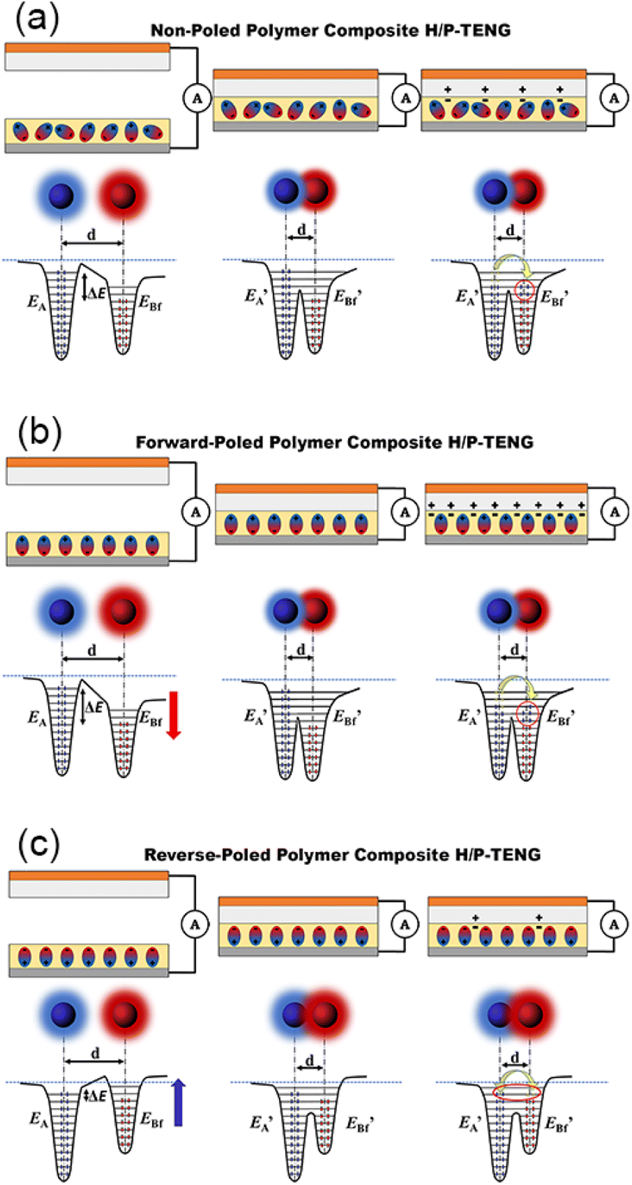 | ||
| Fig. 6 Depiction of overlapping electron cloud (OEC) model for PDMS/BZT–BCT polymer composite-based H/P-TENGs under the (a) non-poled, (b) forward-poled, and (c) reverse-poled conditions, where the blue sphere is the electron cloud of the tribo-positive PVA molecule, and the red sphere is the electron cloud of the tribo-negative PDMS/BZT–BCT molecule. | ||
First, we look at the non-poled H/P-TENG operation. When the two triboelectric layers come into close proximity during the contact phase of the H/P-TENG, the electron clouds of the PVA film and PDMS/BZT–BCT film are able to overlap. When this happens, the potential wells of both triboelectric layers merge, forming a double-well potential as shown in Fig. 6(a). Due to the higher occupied energy levels of the electrons in PVA, this forms an asymmetric double-well, which provide an energy gradient to drive the electrons from the tribo-positive PVA to the tribo-negative PDMS/BZT–BCT energy well. As a result, the PVA film has net positive charges on its surface, whereas the PDMS film has net negative charges.
As the polymer composites are forward-poled, the energy levels shifted downwards, the ΔE increased and subsequently increases the energy gradient of the merged potential well. With an even higher energy gradient, more electrons are driven from the PVA film towards the forward-poled PDMS/BZT–BCT film. This is reflected in the increase of electrical output of the H/P-TENG when the polymer composite films are forward-poled. Under the reverse-poled condition, we predict the energy levels of the electrons are shifted upwards. This has the opposite effect, lowering the ΔE between the PVA film and reverse-poled PDMS/BZT–BCT film. With a narrower ΔE, the energy gradient is also relatively lower, which results in fewer electrons being driven from the PVA film to the PDMS/BZT–BCT film.
We charged several capacitors ranging from 1 μF to 330 μF with our H/P-TENG. The voltage storage versus capacitor charging time for the various capacitors that are measured is depicted with solid lines in Fig. 7(a). When compared to the ranges of capacitors, the 1 μF and 2.2 μF capacitors had a faster charging rate. The 1 μF capacitor is able to charge up to 7 V whereas 2.2 μF capacitor charge up to 6 V within 3 minutes. The total stored energy and charging rates drop significantly when connected to the 6.8 μF capacitor, and even further when the capacitance is ≥10 μF. The voltage stored in the capacitor VC is calculated using the eqn (2) shown below:12
 | (2) |
 | ||
| Fig. 7 (a) Measured (solid lines) and theoretical (dashed lines) charging rate of various capacitors by H/P-TENG constructed with polymer composite film of 15 wt% BZT–BCT inclusion and, (b) H/P-TENG constructed with polymer composite film of 15 wt% BZT–BCT inclusion lighting up 50 commercial blue LEDs. | ||
| Tribo-positive material | Tribo-negative material | Power density (W m−2) | Ref. |
|---|---|---|---|
| PVA | PDMS/BZT–BCT | 7.5 | This work |
| PTFE | ZnO/PVDF | 0.3 | 32 |
| BCZT/PVDF-HFP | Silicon rubber | 0.2 | 51 |
| Stainless steel fabric | PDMS/PVDF-HFP | 3 | 52 |
| PET | PDMS/BTO | 0.4 | 53 |
| Silk nanofibers | BFO-GFF/PDMS | 3 | 54 |
| Copper | BZTO:PDMS | 4 | 55 |
| Aluminium | PDMS/BiTO | 0.2 | 56 |
| Polypyrrole electrodeposited GFP | PDMS/BTO-GFP | 4 | 57 |
| Paper | ZnO/PDMS | 6 | 43 |
| Chitosan/BT | PTFE | 8 | 58 |
| PTFE | C-PS/P(VDF-TrFE) | 8 | 59 |
| PVDF/BTO | Natural rubber | 0.4 | 60 |
| PVA/ZnR | Silicon rubber | 15 | 44 |
Conclusion
We have shown that the inclusion of BZT–BCT piezoelectric ceramic is able to enhance the electrical output of a PDMS-based TENG. With the optimal inclusion of BZT–BCT at 15 wt%, the H/P-TENG is able to achieve open-circuit voltage, Voc, short-circuit current density, Jsc, and short-circuit charge density, Qsc of 113.2 V, 61.1 mA m−2, and 100.7 μC m−2 respectively. The increase in the dielectric constant of the polymer composite films is one of the reasons for the enhancement of the electrical output of the H/P-TENG. In addition, we have shown that the forward-poling direction is optimal for the electrical output of H/P-TENG's where the forward-poled 15 wt% polymer composite recorded the highest Voc (127.1 V), Jsc (66.6 mA m−2), Qsc (117.5 μC m−2) and a maximum power density of 7.5 W m−2, which is equivalent to ∼190% enhancement when compared to the PDMS-based TENG. The overlapping electron cloud (OEC) model is proposed to explain this phenomenon. Our study shows that the inclusion of piezoelectric BZT–BCT is a viable method of enhancing the electrical output of a TENG.Author contributions
S. R. Gopal: conceptualization, methodology, formal analysis, investigation, data curation, writing – original draft, visualization. T. S. Velayutham: conceptualization, formal analysis, funding acquisition, validation, resources, data curation, writing – review & editing, supervision, project administration. W. C. Gan: conceptualization, validation, data curation, review & editing, supervision. J. Y. Cheong: methodology, formal analysis, investigation, visualization. A. E. Soh: methodology, investigation.Conflicts of interest
There are no conflicts to declare.Acknowledgements
The authors gratefully acknowledge financial support from Malaysia's Ministry of Higher Education through the Fundamental Research Grant Scheme [FRGS/1/2018/STG07/UM/02/6].References
- L. Degroote, I. De Bourdeaudhuij, M. Verloigne, L. Poppe and G. Crombez, JMIR Mhealth Uhealth, 2018, 6, e10972 CrossRef PubMed
.
- Y. S. Can, B. Arnrich and C. Ersoy, J. Biomed. Inf., 2019, 92, 103139 CrossRef PubMed
- S. L. Ullo and G. R. Sinha, Sensors, 2020, 20, 3113 CrossRef CAS PubMed
- Y. Hu and Z. L. Wang, Nano Energy, 2015, 14, 3–14 CrossRef CAS
- A. Dewan, S. U. Ay, M. N. Karim and H. Beyenal, J. Power Sources, 2014, 245, 129–143 CrossRef CAS
- K. Munirathinam, D.-S. Kim, A. Shanmugasundaram, J. Park, Y.-J. Jeong and D.-W. Lee, Nano Energy, 2022, 107675 CrossRef CAS
- G. Zhu, B. Peng, J. Chen, Q. Jing and Z. L. Wang, Nano Energy, 2015, 14, 126–138 CrossRef CAS
- Z. L. Wang, J. Chen and L. J. E. Lin, Energy Environ. Sci., 2015, 8, 2250–2282 RSC
- S. Pan and Z. Zhang, Friction, 2019, 7, 2–17 CrossRef
- B. Bera, Imper. J. Interdiscip. Res., 2016, 2, 1263–1271p Search PubMed
- Z. Wang, Rep. Prog. Phys., 2021, 84, 096502 CrossRef CAS PubMed
- J. Y. Cheong, J. S. C. Koay, R. Chen, K. C. Aw, T. S. Velayutham, B. Chen, J. Li, C. Y. Foo and W. C. Gan, Nano Energy, 2021, 90, 106616 CrossRef CAS
- R. I. G. Dharmasena, J. H. Deane and S. R. P. Silva, Adv. Energy Mater., 2018, 8, 1802190 CrossRef
- Y. Zhu, B. Yang, J. Liu, X. Wang, L. Wang, X. Chen and C. Yang, Sci. Rep., 2016, 6, 36409 CrossRef PubMed
- Z. L. Wang, T. Jiang and L. Xu, Nano Energy, 2017, 39, 9–23 CrossRef CAS
- J. H. Jung, M. Lee, J.-I. Hong, Y. Ding, C.-Y. Chen, L.-J. Chou and Z. L. Wang, ACS Nano, 2011, 5, 10041–10046 CrossRef CAS PubMed
- N. Sinha, S. Goel, A. J. Joseph, H. Yadav, K. Batra, M. K. Gupta and B. Kumar, Ceram. Int., 2018, 44, 8582–8590 CrossRef CAS
- B. K. Yun, Y. K. Park, M. Lee, N. Lee, W. Jo, S. Lee and J. H. Jung, Nanoscale Res. Lett., 2014, 9, 4 CrossRef PubMed
- N. R. Alluri, A. Chandrasekhar and S.-J. Kim, ACS Sustainable Chem. Eng., 2018, 6, 1919–1933 CrossRef CAS
- J. Zhang, Y. He, C. Boyer, K. Kalantar-Zadeh, S. Peng, D. Chu and C. H. Wang, Nanoscale Adv., 2021, 3, 5465–5486 RSC
- J. Zhu, Y. Zhu and X. Wang, Adv. Mater. Interfaces, 2018, 5, 1700750 CrossRef
- X. Li, Z.-H. Lin, G. Cheng, X. Wen, Y. Liu, S. Niu and Z. L. Wang, ACS Nano, 2014, 8, 10674–10681 CrossRef CAS PubMed
- X. Yang and W. A. Daoud, J. Mater. Chem. A, 2017, 5, 9113–9121 RSC
- B. Shi, Q. Zheng, W. Jiang, L. Yan, X. Wang, H. Liu, Y. Yao, Z. Li and Z. L. Wang, Adv. Mater., 2016, 28, 846–852 CrossRef CAS PubMed
- M. Zhu, Q. Shi, T. He, Z. Yi, Y. Ma, B. Yang, T. Chen and C. Lee, ACS Nano, 2019, 13, 1940–1952 CAS
- A. R. Mule, B. Dudem, H. Patnam, S. A. Graham and J. S. Yu, ACS Sustainable Chem. Eng., 2019, 7, 16450–16458 CrossRef CAS
- K. Lee, S. Mhin, H. Han, O. Kwon, W.-B. Kim, T. Song, S. Kang and K. M. Kim, J. Mater. Chem. A, 2022, 10, 1299–1308 RSC
- J. S. C. Koay, W. C. Gan, A. E. Soh, J. Y. Cheong, K. C. Aw and T. S. Velayutham, J. Mater. Chem. A, 2020, 8, 25857–25866 RSC
- Z. Li, B. Xu, J. Han, J. Huang and K. Y. Chung, Adv. Energy Mater., 2021, 11, 2101294 CrossRef CAS
- S. He, W. Dong, Y. Guo, L. Guan, H. Xiao and H. Liu, Nano Energy, 2019, 59, 745–753 CrossRef CAS
- J. Liu, D. Yu, Z. Zheng, G. Huangfu and Y. Guo, Ceram. Int., 2021, 47, 3573–3579 CrossRef CAS
- H. H. Singh and N. Khare, Nano Energy, 2018, 51, 216–222 CrossRef CAS
- M. Dietze and M. Es-Souni, Sens. Actuators, A, 2008, 143, 329–334 CrossRef CAS
- A. S. Dahiya, F. Morini, S. Boubenia, K. Nadaud, D. Alquier and G. Poulin-Vittrant, Adv. Mater. Technol., 2018, 3, 1700249 CrossRef
- C. Xue, J. Li, Q. Zhang, Z. Zhang, Z. Hai, L. Gao, R. Feng, J. Tang, J. Liu, W. Zhang and D. Sun, Nanomaterials, 2015, 5, 36–46 CrossRef PubMed
- C.-x. Luo, Y. Wang and P.-w. Li, Acta Electron. Sin., 2022, 50(9), 2189–2195 Search PubMed
- Z. Zhou, X. Du, Z. Zhang, J. Luo, S. Niu, D. Shen, Y. Wang, H. Yang, Q. Zhang and S. Dong, Nano Energy, 2021, 82, 105709 CrossRef CAS
- W. Liu and X. J. Ren, Phys. Rev. Lett., 2009, 103, 257602 CrossRef PubMed
- A. Jayakrishnan, K. V. Alex, A. Thomas, J. Silva, K. Kamakshi, N. Dabra, K. Sekhar, J. A. Moreira and M. J. Gomes, Ceram. Int., 2019, 45, 5808–5818 CrossRef CAS
- J. Liu, B. Yang, L. Lu, X. Wang, X. Li, X. Chen and J. J. S. Liu, Sens. Actuators, A, 2020, 303, 111796 CrossRef CAS
- J. Liu, B. Yang and J. Liu, J. Mater. Sci.: Mater. Electron., 2018, 29, 17764–17770 CrossRef CAS
- G. Suo, Y. Yu, Z. Zhang, S. Wang, P. Zhao, J. Li and X. Wang, ACS Appl. Mater. Interfaces, 2016, 8, 34335–34341 CrossRef CAS PubMed
- H. Patnam, S. A. Graham and J. S. Yu, ACS Sustainable Chem. Eng., 2021, 9, 4600–4610 CrossRef CAS
- Y. P. Lim, J. S. C. Koay, J. Zhao, S. Huang, B. T. Goh, K. C. Aw, B. Chen, C. Y. Haw and W. C. Gan, Adv. Funct. Mater., 2022, 2206750 CrossRef CAS
- H. Jiang, H. Lei, Z. Wen, J. Shi, D. Bao, C. Chen, J. Jiang, Q. Guan, X. Sun and S.-T. Lee, Nano Energy, 2020, 75, 105011 CrossRef CAS
- Y. W. Kim, H. B. Lee, J. Yoon and S.-H. Park, Nano Energy, 2022, 95, 107051 CrossRef CAS
- Y. Xie, Q. Ma, H. Qi, X. Liu, X. Chen, Y. Jin, D. Li, W. Yu and X. J. N. Dong, Nanoscale, 2021, 13, 19144–19154 RSC
- Z. Zhang, Q. Zhang, Z. Zhou, J. Wang, H. Kuang, Q. Shen and H. Yang, Nano Energy, 2022, 101, 107561 CrossRef CAS
- Z. Song, W. Li, H. Kong, Y. Bao, N. Wang, W. Wang, Y. Ma, Y. He, S. Gan and L. Niu, Nano Energy, 2022, 92, 106759 CrossRef CAS
- S. Lin, C. Xu, L. Xu and Z. L. Wang, Adv. Funct. Mater., 2020, 30, 1909724 CrossRef CAS
- Y. Wu, J. Qu, W. A. Daoud, L. Wang and T. Qi, J. Mater. Chem. A, 2019, 7, 13347–13355 RSC
- A. Maitra, S. Paria, S. K. Karan, R. Bera, A. Bera, A. K. Das, S. K. Si, L. Halder, A. De and B. B. Khatua, ACS Appl. Mater. Interfaces, 2019, 11, 5022–5036 CrossRef CAS PubMed
- C. Rodrigues, A. Gomes, A. Ghosh, A. Pereira and J. Ventura, Nano Energy, 2019, 62, 660–666 CrossRef CAS
- J. Liu, D. Yu, Z. Zheng, G. Huangfu and Y. J. Guo, Ceram. Int., 2021, 47, 3573–3579 CrossRef CAS
- W. Wang, J. Zhang, Y. Zhang, F. Chen, H. Wang, M. Wu, H. Li, Q. Zhu, H. Zheng and R. Zhang, Appl. Phys. Lett., 2020, 116, 023901 CrossRef
- S. Hajra, A. M. Padhan, M. Sahu, P. Alagarsamy, K. Lee and H. J. Kim, Nano Energy, 2021, 89, 106316 CrossRef CAS
- A. Maitra, R. Bera, L. Halder, A. Bera, S. Paria, S. K. Karan, S. K. Si, A. De, S. Ojha and B. B. J. R. Khatua, Renewable Sustainable Energy Rev., 2021, 151, 111595 CrossRef CAS
- S. Pongampai, T. Charoonsuk, N. Pinpru, P. Pulphol, W. Vittayakorn, P. Pakawanit and N. E. Vittayakorn, Composites, Part B, 2021, 208, 108602 CrossRef CAS
- L. Yao, Z. Zhang, Q.-l. Zhang, Z. Zhou, H. Yang and L. Chen, Nano Energy, 2021, 86, 106128 CrossRef CAS
- J.-H. Zhang, Z. Zhou, J. Li, B. Shen, T. Zhu, X. Gao, R. Tao, X. Guo, X. Hu and Y. Shi, ACS Mater. Lett., 2022, 4, 847–852 CrossRef CAS
Footnote |
| † Electronic supplementary information (ESI) available. See DOI: https://doi.org/10.1039/d3ra00077j |
| This journal is © The Royal Society of Chemistry 2023 |