 Open Access Article
Polymer-based graphene composite molding: a review
F. Xu ab,
M. Gaob,
H. Wang*c,
H. Liub,
F. Yan*a,
H. Zhaod and
Q. Yaoa
aSchool of Mechanical Engineering & Automation, University of Science and Technology LiaoNing, Qianshan Centre Road 189#, 114051, Anshan, China. E-mail: xufan-00@126.com
bSchool of Mechanical Engineering, Jiangsu University, Xuefu Road 301#, Zhenjiang, 212000, China
cNingbo Sunny Optoelectronic Information Co., Ltd, Yuyao, 1918#, Ningbo, Zhejiang, China
dSchool of Mechanical & Power Engineering, Yingkou Institute of Technology, Bowen Road 46#, 115014, Yingkou, China
First published on 17th January 2023
Abstract
Polymer-based graphene composite products with high mechanical properties, heat resistance, corrosion resistance and electrical conductivity are obtained by different molding technologies. Although these processes conveniently realize the molding of polymer composites, it is often difficult to control the product quality because of the fluctuation of the temperature and pressure threshold. At the same time, a high temperature or external load will carbonize polymer composites or cause excessive porosity to influence the compacted density and electrical conductivity. In this review, additive manufacturing, injection molding, extrusion molding, hot pressing, spark plasma sintering, electromagnetic-assisted molding and other processing methods were introduced. Meanwhile, the powder molding mechanism and material constitutive model were introduced, providing appropriate molding methods and theoretical guidance based on the performance of raw materials and the performance requirements of products.
1. Introduction
With the rapid development of aerospace, automotive, medical and health, military and other fields, polymer composites have become important engineering materials because of their mechanical properties, corrosion resistance, thermal conductivity, light weight and other characteristics.1 Moreover, combinations of polymers and one or more other material that integrates the physical and chemical properties of various materials are widely used in aerospace, biomedical, automotive parts, electrodes, packaging materials and oil mining.2–4In the process of oil exploration and production, some parts work in highly corrosive and low-conductivity media. Electromagnetic flowmeters (EMFs) are used to monitor crude oil flow to monitor the working condition of the device. At present, the electrode material of EMF is primarily composed of 316 L stainless steel, titanium, iridium and other metal materials.5 Considering that there is a large volume of formation water in the well and it contains Ca2+, Mg2+, CO32− and other impurities, it is easy to produce inorganic salt precipitation on the surface of the equipment, thereby reducing the measurement accuracy and service life of the electromagnetic flowmeter.6 Thus, a light corrosion-resistant electromagnetic force flowmeter is needed for petroleum exploration systems to monitor crude oil flow.
Semiconductor materials synthesized from polymers have received extensive attention compared with metal materials. Adding nanomaterials to polymers can improve their corrosion resistance, and a small number of filler materials can significantly improve the performance of polymers to meet the requirements of light weight.7 In addition, the interaction between the filler and matrix causes the particle size to affect the physical and chemical properties of composites.8 Graphene, as an efficient nanofiller, allows a large change in the properties of composite materials at an extremely low percolation threshold because of its ultrahigh aspect ratio and special planar hexagonal lattice structure.9 Graphene has a large surface area, excellent electrical conductivity, and easily forms a good conductive network in the polymer matrix. Graphene, as a filling material, has become an important material for polymer preparation.10 The tensile strength and thermal deformation temperature of nanocomposites are higher than those of other large filling materials. Common nanofillers include carbon nanofibers, carbon nanotubes, carbon black, expanded graphite and graphene.11–14
Graphene has high electrical conductivity,15 high strength16 and good thermal conductivity; thus, it has become the preferred semiconductor filler material.17 It forms a semiconductor polymer, and the polymer has high mechanical, chemical and electrical properties. Hence, it can replace or temporarily replace metal materials as conductors in the fields of aviation, aerospace, automobile, organ repair, and so on.
Conductive graphene composites are synthesized from graphene and acrylonitrile butadiene styrene (ABS), epoxy resin (EP), polycarbonate (PC), polypropylene (PP), polystyrene (PS), polyethylene (PE), polyether ether ketone (PEEK), and polyether ketone (PEKK).9,14 The performance of PEKK is similar to that of PEEK, but in situ polymerization has a small splash, low price, and high safety. Furthermore, PEKK only reacts with concentrated sulfuric acid, with strong corrosion resistance, and only 0.5% of its adsorption for water vapour. In addition, its melting point reaches 380 °C, and it can work for a long time below 250 °C. It is further explained that PEKK is an important material for national defense and military industry because of its advantages, such as corrosion resistance, wear resistance, and oil resistance.18,19 Graphene/PEKK composites not only have the above characteristics but also ensure that the materials have high mechanical properties and electrical conductivity.
The properties, forming methods, graphene content, Young's modulus, tensile strength, conductivity, and thermal conductivity of graphene composites with different matrices are shown in Table 1. Among them, the tensile strength of graphene/PEKK is much higher than that of the other composites. Research shows that Young's modulus and conductivity can be improved by increasing the graphene content. The differences in electrical conductivity and mechanical properties of polymer composites with the same matrix under different molding conditions are also shown in the table and are worthy of attention.
| Matrix | Moulding method | GR/% | E/GPa | σb/MPa | ρ/S m−1 | Kx/K W−1 m−1 |
|---|---|---|---|---|---|---|
| ABS20 | Fused deposition modeling | 4 | 2.46 | 35.9 | — | — |
| EP21 | Casting molding | 5 | 5.6 | 50.3 | 5 | 1.5 |
| PC22 | Injection molding | 3 | 2.27 | 81 | 11.36 | — |
| PP23 | Extrusion molding | 2 | 0.95 | 29 | 12.2 | — |
| PS24 | Hot pressing molding | 4 | 1.03 | 12.8 | — | — |
| PE25 | Injection molding | 4 | 1.8 | 26 | — | — |
| PEEK26 | Selective laser sintering | 0.5 | 3.15 | 107 | 7.7 × 10⁻⁹ | — |
| PEEK27 | Hot pressing molding | 3 | 3.07 | 106.2 | 0.1 | — |
| PEKK28 | Spark plasma sintering | 5 | — | — | 16.4 | — |
| PEKK29 | Hot pressure molding | 2 | 3.07 | 186 | — | — |
| PEKK30 | Electromagnetic molding | 3.8 | — | — | — | — |
At present, increasing attention has been given to the formation and application of graphene composites, which have gradually become a research hotspot in the past decade.1,2,15,18 The primary molding methods for graphene composites include additive manufacturing, hot pressing, spark plasma sintering, injection molding, extrusion molding, and electromagnetic pulse powder compaction.
This study reviewed several typical molding methods of polymer-based graphene composites and described the molding process and molding mechanism of polymer-based graphene composite powder (Section 2). Different constitutive models of materials are also discussed, and the assumptions, applications, and shortcomings of these models are summarized. Section 3 introduces the powder-forming theory, including the powder compaction equation, the yield criterion of geotechnical plasticity, the micromechanical model and the ellipsoidal yield criterion. The application characteristics and prospects of different theories are compared, thus providing theoretical guidance for the formation of graphene composites and even other polymer materials.
2. Methods
2.1. Additive manufacturing
Additive manufacturing is a technology for 3D printers to read the section information of STL files describing the surface shape of 3D objects to realize layer-by-layer manufacturing.31 Its advantages, such as melt deposition and laser sintering, are that they do not need molds to manufacture the products. However, the printing speed is slow, and the requirements for physical and chemical properties and dimensions of materials are high; hence, mass production cannot be achieved. The additive manufacturing products also express evident anisotropy and have large porosity, particularly after adding reinforcement materials, and the anisotropy and porosity of materials are more evident.32 Arevo33 successfully printed PEKK composites using direct energy deposition (DED) technology, in which the reinforcement materials include carbon fibre, aramid fibre, and glass fibre. The six-axis robot printing platform can realize 3D curved surface printing, thus making the adhesion between layers better and the porosity smaller; however, it cannot control the anisotropy of materials.Graphene nanoplatelets were incorporated at 4 wt% in acrylonitrile–butadiene–styrene (ABS) filaments, which were used to feed a fused deposition modeling machine to obtain specimens with various build orientations,20 as shown in Fig. 1. Although the elastic modulus and dynamic storage moduli of the products increased, the stress and strain at break decreased. Thus, improving the overall performance of products may be an important goal of FDM printing.
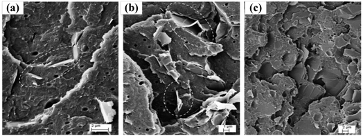 | ||
| Fig. 1 Graphene composites:20 (a) 4-H; (b) 4-V; (c) 4-P. | ||
2.2. Injection molding
Injection molding is a process that heats and melts polymers, metals, and other materials and uses pressure to inject them into the mold for cooling molding.34,35 H. Massé et al.34 included an overview of the injection molding process, the primary characteristics of the flow patterns during filling that were relevant to fibre orientation, and a review of experimental observations of fibre orientation in injection-molded parts, including fibre orientation around weld lines. Finally, an outline of modeling techniques used in the prediction of fibre orientation in injection molding is presented. This molding process is widely used. France Arcoma Company has developed different series of products by injection molding. The filler materials include carbon and glass fibres. Both of these reinforcing materials have significantly improved the Young's modulus and tensile strength of PEKK composites. The tensile strength can reach more than 250 MPa; however, the conductivity is low.36 The molding temperature of injection molding is higher than the melting temperature of materials, whereas the melting temperature of PEKK exceeds 360 °C, which makes its cooling time longer, increases the production cycle, and reduces production efficiency. Meanwhile, the internal stress of injection molded products is large, particularly when the mold is changed, and the sample easily cracks caused by the uneven cooling rate. However, product quality cannot be guaranteed when processing products with complex shapes and large sizes; thus, the product shape and size of this forming process are greatly limited.Fig. 2 shows an SEM image of the fracture surfaces of the S-PC/GNS nanocomposites with 3.0 wt% GNS contents, and the lamellar graphene is distributed on the matrix. Blue and red arrows indicate aggregated and individual graphene nanosheets, respectively. Comparing Fig. 1 and 2, the lamellar graphene is distributed on the matrix. Meanwhile, the density of the specimen obtained by injection molding is better than the density of the specimens obtained by additive manufacturing.
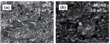 | ||
| Fig. 2 SEM image of fracture surfaces of S-PC/GNS nanocomposites with 3.0 wt% GNS contents: (a) GNS; (b) MGNS.22 | ||
2.3. Extrusion molding
Extrusion molding, also known as plasticizing extrusion, is the process of extruding the powder or green body in the die material to form different forms of the green body or other final products under pressure.37,38 Akoma39 processed PEKK into complex products such as gears and racks using the extrusion molding process. However, the extrusion molding time is long, and the pressure and crystallinity are high. Hence, it is necessary to pay attention to the melting and glass transition temperatures, as the product quality is highly sensitive to temperature. A. Bendada and M. Lamontagne37 proposed a new infrared pyrometer for polymer temperature measurement during extrusion molding. The key feature of the developed system is the use of two specific wavelengths that correspond to the fundamental absorption bands of PET. This paper shows the importance of temperature as an influencing factor for product quality.Giulia Infurna et al.23 discussed two carbonaceous nanofillers influencing the nanocomposite properties, as shown in Fig. 3. Moreover, the radical scavenging role of the carbonaceous nanofillers was investigated under thermomechanical, thermal, and photodegradation conditions. The results confirmed that the aspect ratio, loading, and dispersion level of the filler play determinant roles in the nanocomposite durability. All the specimens containing a single type of carbonaceous nanoparticle have a high resistivity value during extrusion molding.
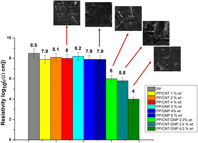 | ||
| Fig. 3 Electrical resistivity of polypropylene and its nanocomposites.23 | ||
2.4. Hot pressing molding
Hot pressing, also known as hot pressing sintering, is divided into solid- and liquid-phase sintering. The powder compaction and sintering processes are simultaneously carried out, and the sintering temperature is generally 70–80% of the melting point. During the sintering process, it is often necessary to add auxiliary materials to speed up the discharge of impurities and gas from the compact billet.27,29 The sintered body obtained by hot pressing sintering has fine grains and a uniform distribution, with a density of more than 96%, and the pressure is generally 30–50 MPa.40 Quanbin Wang et al.29 utilized hot pressing to process graphene/PEKK composite slabs with different graphene contents in their work and carried out tensile strength tests on the formed plates. Fig. 4 shows that when the graphene content is 2.5%, the maximum modulus is 3.62 GPa, and the tensile strength is 120 MPa. The hot-pressing molding process has a long pressure holding time and low production efficiency. Die materials often include graphite, which can be easily damaged and has a short service life. In general, resistance heating is the heating method, which consumes high electric energy and is costly.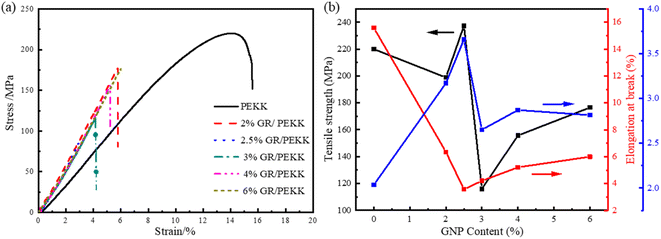 | ||
| Fig. 4 Tensile measurement for PEEK and graphenex/PEEK composites:29 (a) stress–strain curves from uniaxial tensile tests; (b) performance of composite materials. | ||
Fig. 5 shows SEM images of NG and graphene prepared under chemical reduction conditions. CRG-KH550 was sufficiently exfoliated to thin graphene sheets with larger interlayer spacing compared with TRG, which was related to the reduction method. Finally, Lilong Yang et al.27 concluded that composites with excellent electrical conductivity were fabricated by a hot-pressing technique based on a PEKK matrix and graphene. It can be determined that temperature and pressure must be the most important objects of concern during hot-pressing.
 | ||
| Fig. 5 (a) SEM images of natural graphite;27 (b) CRG-KH55; (c) TRG. | ||
2.5. Spark plasma sintering
Spark plasma sintering (SPS) is a sintering process in which powder samples are loaded into conductive molds and a pulsed current is applied under uniaxial pressure.41–43 Although the density of SPS-formed products reaches 98–100%,44 the powder materials are not completely transformed because of the short sintering time. Fan et al.31 studied the SPS forming process of graphene/PEKK composites and tested the conductivity and mechanical properties of the formed specimens. The conductivity of the specimens increases continuously with increasing graphene content. The conductivity of graphene is the best when its content is 5%, with a conductivity of 16.4 S m−1, and the compressive strength of the graphene/PEKK composite exceeds 110 MPa. It is further proven that the conductivity and mechanical properties of the sample with 5% graphene content are enhanced. However, it remains difficult to improve the compaction density of graphene/PEKK composite powder, particularly the cooling rate. This is because the conductivity of particles affects the quality of plasma sintering, and it is difficult to control the sintering temperature.Fig. 6 shows the SEM analysis of the brittle fracture of the electrode bar for the graphene/PEKK composite material with 5% graphene. They can be found without evident graphene agglomeration and carbonization, and graphene is uniformly dispersed in the substrate PEKK. Fig. 6(b) and (c) show the fake graphene of the graphene/PEKK composite electrode bar in the A and B regions. This further explains the conductivity of the graphene/PEKK composite with 5% graphene from the tissue structure.
 | ||
| Fig. 6 SEM analysis of the electrode bar for the 5% graphene/PEKK composite material:28 (a) SEM analysis of the electrode bar including sections A and B; (b) microstructure in region A; (c) microstructure in region B. | ||
2.6. Electromagnetic-assisted molding
Explosive molding is a special molding process with high-speed impact.45–47 Experiments and finite element numerical analysis have proven that molding speed is a key factor affecting product quality. Therefore, controlling the explosive impact speed is an important technique to improve molding quality. During the explosive molding process, high-speed forming technology is controlled by a heavy hammer. The compaction speed is controlled by adjusting the height of the heavy hammer; however, noise pollution cannot be avoided.Fig. 7 shows the forming principle of a typical high-speed molding device. Magnetic pulse powder compaction technology is also a rapid prototyping method. The powder was impacted in the stress wave at high speed. Powder particles are subjected to elastic–plastic deformation during molding, and their mechanical properties are further improved. Generally, the molding speed is controlled by adjusting the discharge voltage to avoid noise pollution and energy loss caused by the impact of the punch and improve the molding quality.
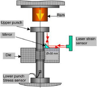 | ||
| Fig. 7 High-velocity compaction schematic diagram.48 | ||
Previous studies have primarily focused on metals, metal composites,49–53 inorganic nonmetallic materials,54–56 and other powder materials with good conductivity and thermal conductivity. Few people have studied the electromagnetic molding of polymers and their composites. Wang et al.30 studied the molding of graphene/PEKK composite powder using electromagnetic pulse powder compaction technology and obtained the influence rule of the main process parameters on the electromagnetic pulse compaction molding quality of graphene composite. They will further study how powder particles influence the quality under the electromagnetic molding. Magnetic pulse powder compaction technology can be divided into radial and axial compaction,57,58 and its principle is shown in Fig. 8. Magnetic pulse powder compaction technology can realize the molding of polymer composite powder under the action of stress waves. The compaction speed is controlled by controlling the discharge time, voltage and capacitance.
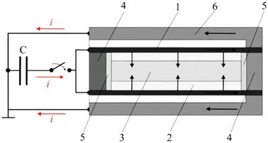 | ||
| Fig. 8 Principle scheme of magnetic pulse compaction of tubes: (1) copper shell; (2) powder; (3) steel rod; (4) plug; (5) spacer; (6) reverse conductor.57 | ||
During high-speed compaction, the punch transmits the stress wave to the powder, thereby causing severe plastic deformation of the powder during compaction. In addition, the fine powder particles and broken powder particles are rapidly filled together because of the friction, extrusion, shearing, and other effects between powder particles, and the relative density is further improved.59,60 Moreover, the stress wave is repeatedly reflected, consumed, and attenuated during compaction, and multiple stress waves can increase the relative density of powder through multiple compactions. Under high-speed impact, the rotation, rearrangement, and plastic deformation of the powder occur in a very short time to avoid carbonization caused by high temperature.
The friction between the powder particles and between the particles and the mold generates heat caused by the extremely short compaction time (μs). The heat cannot diffuse, which leads to an increase in the powder temperature in the mold, which is conducive to particle deformation.61 The energy of electromagnetic pulse compaction molding can be changed by changing the discharge parameters compared with explosion molding. Its impact speed can be controlled from several meters per second to tens of meters per second compared with heavy hammer high-speed forming.
3. Power molding theories
The powder-forming process discussed above is complex. The traditional trial and error method relies on the experience of designers and lacks theoretical guidance. Various experiments are necessary to revise the design scheme, thereby resulting in a long product development time cycle and high cost. Although these methods can obtain products that meet the requirements, there remains no unified theory on the deformation mechanism of powder forming, which will lead to different products needing to repeat the same work and increase costs. Therefore, it is necessary to apply computer numerical simulation technology to predict product molding and optimize its molding process plan.62,63In practical modeling, secondary factors are often ignored to simplify the model, and the prediction accuracy of powder compaction depends on the model's accuracy. The powder is a whole composed of particles. Individual particles are continuous, but there are pores between particles; hence, the whole composed of particles is discrete. The discontinuous problem is more complex; hence, both the powder and the performance of a particle should be considered as a whole. At present, although there are various studies on the numerical simulation of powder compaction, there is no mathematical model that can accurately predict the powder compaction process. The theories proposed by academia primarily include the compaction equation, ellipsoidal yield criterion, yield criterion of geotechnical plasticity, and micromechanical model.
3.1. Powder compaction equation
The compaction equation of powder is the relationship between the relative volume of powder and pressure. Various researchers have made many important achievements and have successively proposed different compaction equations. The most widely used equations include Balshin, Kawakita, Heckel, and Huang Peiyun's equations.64,65 This is a huge step since Walker first proposed the model in 1923. The theoretical and empirical formulas are shown in Table 2.66The above compaction equation has led to various ideal treatments, such as ignoring the density gradient and stress gradient inside the powder, which makes it difficult to explain the uneven distribution of strength and hardness of the final compact. Thus, it is assumed that the powder particles are elastic, and the work hardening phenomenon and the friction between the powder particles are ignored. The relationship between the pressure and density of the compact is described by an empirical formula. The compaction process is accompanied by sintering, and ensuring the prediction accuracy by ignoring the influence of temperature is difficult. At present, the limitations of the models remain difficult to solve. However, researchers have also made great progress; they modified the model or modified the application, which has become a key direction of research.
3.2. Yield criterion of geotechnical plasticity
Considering that rock soil and powder are particles in a loose state, the plastic mechanics theory of rock soil is used in powder forming. Based on geotechnical plasticity, hydrostatic pressure has a great influence on the yield of materials.67,68 At present, the plastic mechanical models of rock and soil used to describe the powder compaction process primarily include the Cap model,69 modified Cam Clay model,70 Mohr–Coulomb model71 and Drucker–Prager/Cap model.72,73The Mohr–Coulomb and Drucker–Prager models are the earliest in the application of geotechnical plasticity. However, for the study of powder compaction theory, both of these models believe that the powder can be infinitely pressed. In addition, both models are based on the assumption of the associated flow rule, which will lead to deviation in the calculation results. Researchers found that the above shortcomings can be overcome by adding a surface at the end of two conical surfaces, thus forming a typical dual mechanism model. It generally consists of shear failure and cap yield surfaces, where Drucker–Prager/Cap is the most widely used model.74–78 The model is represented in the p–q plane, as shown in Fig. 9,74 and consists of three curves: shear failure surface Fs, transition zone Ft and cap yield surface Fc, which are defined by eqn (1). Moreover, Wenting He et al.79 adopted the modified Drucker–Prager/Cap model to simulate the cold isostatic pressing process of alumina ceramic and epoxy composite powder and determined the optimal corner radius through numerical analysis. They think that the combination of the shear failure and cap yield surfaces is more suitable to describe the compaction process of powder. Meanwhile, Mengcheng Zhou et al.78 successfully applied the theory of Wenting He, and they compared the simulation and experimental results and achieved good results.
Fs = q − p![[thin space (1/6-em)]](https://www.rsc.org/images/entities/char_2009.gif) tan tan![[thin space (1/6-em)]](https://www.rsc.org/images/entities/char_2009.gif) β − d = 0 β − d = 0
| (1) |
 | (2) |
 | (3) |
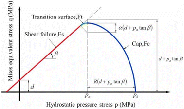 | ||
| Fig. 9 The modified Drucker–Prager Cap model.74 | ||
In addition, Khoei et al.80,81 established a dual mechanism density relationship model (Fig. 9) and simulated the large deformation during the powder compaction process. Although all Cap models are based on the continuous yield theory of materials, the stress state in most models is a 3D stress state based on the law of invariant mechanics. Meanwhile, the yield surface must include a moving “cap” surface in the powder elastoplastic model. The position of the surface of the moving “cap” can be expressed by a plastic volumetric strain equation and expanded based on a certain hardening law. The yield surface can be divided into three sections (Fig. 10), and the expression is as follows:
 | (4) |
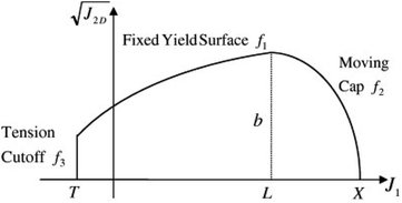 | ||
Fig. 10 The expression of the dual-mechanism model proposed by Khoei in  space.81 space.81 | ||
The axisymmetric and nonaxisymmetric parts are numerically simulated and analysed using the numerical finite element method. The density and stress gradients82,83 are obtained and compared with the test data to verify their reliability.
 | (5) |
However, the model parameters need to be calibrated many times, and the process is complex. Diarra et al.84 compared the modified Drucker–Prager/Cap model with the modified Cam–Clay model and showed that the prediction results of the two models were almost the same; meanwhile, the modified Cam Play model was more concise. Its representation in p–q space is shown in Fig. 11,84 and its expression is shown in eqn (5). However, it cannot bear the static tensile load because the model does not consider the adhesive force between particles; thus, its mechanical properties are different from those of powder materials.
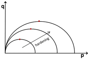 | ||
| Fig. 11 Representation of the modified Cam–Clay model in the p–q plane: evolution of the yield surface with the relative density.84 | ||
3.3. Micromechanical model
The mechanical properties of the powder are related to the particle size distribution, composition ratio, material type, and other factors. In addition, its mechanical properties have an impact on the compaction process of the powder. The powder compaction process is a complex molding process, and various factors affect the quality of compacts, such as the force between particles and viscosity. The molding law is often revealed through discontinuous medium mechanics, powder particles are regarded as a group of powder particles, and the relationship between the movement characteristics of each particle and the macroscopic mechanical behavior of the powder is established.85 In micromechanics theory, compacts are primarily regarded as compact spherical particle aggregates. At present, there are two primary methods: discrete element and hole model methods.The discrete element method was initially proposed by Cundall et al.86 to analyse the distribution and velocity of a single element in space. Afterward, scholars applied this method to the process of powder compaction, discretized the powder movement into independent units, and analysed the independent movement of each unit, and the movement of each unit conformed to the classical equation of motion. Meanwhile, Wen Tong et al.87 used the discrete element method to conduct a finite element simulation of the powder and analysed its movement speed, trajectory, and density distribution. Yan Shiwei et al.88 successfully predicted the temperature evolution process during the electromagnetic pulse compaction of iron powder using the discrete element method. They found that the temperature rise came from the plastic deformation of the powder. The friction between the powder particles and the friction between the particles and the mold affect the temperature gradient, and the compaction speed has a greater impact on the temperature rise. The temperature and temperature gradient of the iron powder increase continuously with increasing compaction speed. Ransing et al.89 established a multiparticle model to analyse the compaction process of mixed ductile and brittle powders and compared it with the Gurson model of continuum mechanics. The results of the two prediction models were similar, which proved that the discrete model was capable of describing the formation of powder particle aggregates. However, their research has made an idealized assumption on powder particles; hence, it remains unable to predict the compression of large particle combinations.
The pore model method sets the pores of the powder uniformly in the continuum and then uses the numerical simulation method to solve. Zhou Zhaoyao et al.90 used MSC MARC software to predict the upsetting process of iron powder sinter by setting pores with the same size and uniform distribution and analysed the mechanical behavior of particles, as shown in Fig. 12. The model takes into account the relationship between the powder and the compact body and can better describe the molding characteristics under the assumption that the pore size and shape are the same and its distribution is uniform.
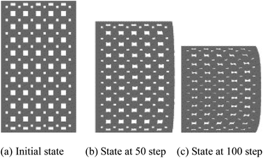 | ||
| Fig. 12 Hole model of the sinter upsetting process.90 | ||
The micromechanical model can well describe the process of powder accumulation and early compaction; however, there is a large deviation after the powder particles change from elastic deformation to plastic deformation. In the model, the powder particles are assumed to be regular spherical particles, with severe deformation between particles, thus breaking the regularity and making the force between particles complex. The existing micromechanical models are simple, ignoring the difference between the ideal model and the actual model. This leads to the difference between the experimental results and numerical analysis results. Therefore, selecting a reasonable micromechanical model remains an effective technique to improve prediction accuracy.
3.4. Ellipsoidal yield criterion
The ellipsoidal yield criterion is based on the Von Mises yield criterion, which considers the influence of hydrostatic pressure and relative density on the flow stress. The powder is assumed to be a “compressible continuum”; hence, continuum mechanics theory is applied.91,92 The classic von Mises yield criterion is expressed as follows:
 | (6) |
The yield formula is:
 | (7) |
 | (8) |
 is the second invariant of the deviator stress tensor, J1 is the first invariant of the stress tensor, η is the flow stress model and relative density function, and σs is the yield stress of the material when the relative density is equal to 1. In the principal stress space, it appears as an ellipsoid after the introduction of hydrostatic pressure and relative density. The
  plane is elliptical. When the powder is nearly fully dense, that is, when the relative density is 1, the yield equation degenerates to the Mises yield criterion, as shown in Fig. 13.93
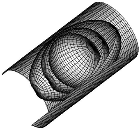 | ||
| Fig. 13 Evolution of the ellipsoidal surface during powder compaction.93 | ||
Since the 1970s, various scholars have proposed the yield criterion of ellipsoidal powder. Doraivelu,94 Green,95 Shima-Oyane,96 Kuhn-Downey,97 Gurson,98 and Song Yi99 proposed the influence of hydrostatic pressure and porosity on the yield criterion based on the classical von Mises of metal material mechanics theory and determined different yield conditions, as shown in Table 3. The above formulas have similar forms, and they can be used for different materials or different molding methods by adjusting their boundary conditions and parameters.
| Author | A, B | η | Remark |
|---|---|---|---|
| Doraivelu94 |  |
 |
If ρ = 1, B = 0 and η = 1 |
| Green95 |  |
 |
If ρ = 1, B → 0 and η = 1; if ρ = 0, B → +∞ and η = 0 |
| Shima and Oyane96 |  |
ρ5 | If ρ = 1, B = 0 and η = 1; if ρ = 0, B → +∞ and η = 0 |
| Kuhn and Downey97 |  |
1 | If ρ = 1, B = 0 |
| Gurson98 |  |
ρ2 − ρ + 1 | If ρ = 1, B = 0 and η = 1 |
| Yisong99 | A = 1.86ρ + 1.14 |  |
If ρ = 1, B = 0 and η = 1 |
| B = 0.31(1 − ρ) | |||
| Xu100 | A = 1.86ρ + 1.14 |  |
If ρ = 1, m∈[0, 0.62] n > 1 |
| B = m(1 − ρ) |
In summary, the ideal compaction equation cannot completely and accurately explain the powder compaction process. If only the compaction equation is used to describe the powder compaction process, it will cause a large deviation, and the prediction accuracy is limited. Although the plastic mechanical model of rock and soil has a good theoretical basis and can describe the mechanical behavior of powder, its constitutive model is complex; hence, various mechanical tests are necessary to calibrate the parameters.101 The micromechanical model assumes that the powder is a round particle; however, its actual particle shape is irregular, and the interaction between particles is complex. The ellipsoidal yield criterion requires fewer parameters to be determined compared with these models. Moreover, the reliability of simulation prediction accuracy for axisymmetric and nonaxymmetrical bodies has been verified and widely recognized.102–106 Fan Xu et al.100 used the modified Doraivelu model to predict the cold compaction process of PEKK powder, which can better predict the experimental process of the density, thus further confirming the feasibility of this theory on PEKK composites.
Theoretically, porous materials need to consider the effects of porosity and hydrostatic pressure; thus, the yield criterion can generally be expressed as eqn (9).99
 | (9) |
 and J1 are the second and first invariants of the deviatoric stress tensor, respectively. σs is the yield stress of the material in a dense state, and η is a relative density function and represents the contribution of geometric hardening. A, B and η must meet the following conditions:
 | (10) |
That is, when the compact is in a fully dense state, it degenerates into the von Mises yield criterion. Fan Xu et al.100 modified the Doraivelu94 constitutive model based on the linear equation of Poisson's ratio and relative density of iron powder compaction, yield coefficient B,107 and flow stress model106 as follows:
 | (11) |
With the development of finite element technology, various finite element software programs are emerging. Various large-scale commercial software programs, such as ANSYS, MARC, and ABAQUS, have been widely used in various fields. In the numerical analysis of electromagnetic pulse powder compaction, Shi Jian108 used ANSYS software to simulate the electromagnetic pulse compaction process and applied the Drucker Prager yield criterion to conclude consistently with the experimental results. Meanwhile, Partha AP et al.109 successfully predicted the powder compaction process using ANSYS software. By comparing one-way compaction with two-way compaction, the compactness of two-way compaction is 15% higher than that of one-way compaction, and the compactness increases with increasing compaction pressure.
Haifeng Hu et al.110 successfully analysed the mechanical behavior of the powder using ABAQUS software and simplified it into a dense volleyball stacking model. The comparison of simulation and experimental results proves that the assumed dense volleyball stacking model is simple and effective. A. R. Khoei et al.111 developed an integrated simulation module consisting of inverse optimization and finite element methods using ABAQUS software. The maximum error between densities is 2.3% compared with the experimental results. Fenqiang Li et al.112 predicted the radial compaction process of electromagnetic pulse powder using the Drucker Prager Cap model and ABAQUS/Explicit. The reliability of the model was verified through experiments, and the uniformity of compaction speed, pressure, and density distribution was predicted. Orest et al.113 adopted a new friction-assisted compaction technology that uses the friction force at the powder punch interface to assist powder compaction. The simulation results show that this technique can greatly reduce the nonuniformity of the density distribution. Xu Fan et al.100 used the modified Doraivelu model to predict the PEKK cold compaction process and obtain the compaction density distribution under different pressures. Although the prediction accuracy of the entire model process was poor and had a high initial relative density, it could still accurately predict the average relative density at the end of compaction. Therefore, we must successfully obtain a constitutive model to predict the powder molding process to obtain some process parameters.
4. Conclusions
Research on polymer composite powder molding can effectively improve the quality of polymer composite products. Herein, the molding equipment, molding mechanism and numerical analysis are discussed. The electrical conductivity and mechanical properties of graphene composites are a form of product existence; thus, selecting appropriate research methods is necessary to improve product performance and application prospects.(1) There are various graphene composite powder-forming equipment and process methods. Hot pressing, spark plasma sintering, additive manufacturing, electromagnetic pulse compaction and other process methods are the main methods to form graphene composite materials. However, an appropriate forming method must be selected to ensure that graphene composite materials have high mechanical properties and electrical conductivity. These forming schemes can also be used in combination; that is, to ensure density, they also eliminate carbonization caused by high temperatures.
(2) Regardless of the kind of molding process scheme, the powder particles are bonded together through temperature or pressure. Hot pressing, spark plasma sintering, injection molding and addictive manufacturing are inseparable from the influence of temperature. Electromagnetic composite molding relies on the discharge voltage or discharge capacitor to achieve high-speed aggregation of particles. However, the heat generated by high-speed impact cannot be released in time; hence, it is often necessary to increase the sintering process after compaction.
(3) It is necessary to establish an appropriate constitutive model to predict the change rule of process parameters during the forming process of graphene composite powder. In addition, different forming process schemes are used for various hypotheses of the constitutive model. The forming materials often sacrifice the prediction accuracy of one aspect of the model. Therefore, the selection or construction of the constitutive model of graphene composite powder is the basis for composite molding experiments and theoretical research.
Author contributions
Funding acquisition, Fan Xu, Hong Liu; writing-original draft, Huixiong Wang and Fan Xu; validation and investigation, Feng Yan and Huixiong Wang; data curation, formal analysis and preparation of materials, Quantong Yao, Feng Yan and Ming Gao; preparation of materials, Hong Liu and Huiyan Zhao.Conflicts of interest
The authors declare that they have no known competing financial interests or personal relationships that could have appeared to influence the work reported in this paper.Acknowledgements
This work was supported by the University science and technology Liaoning Special funding project for high-level talent research and construction, Natural Science Research in Universities of Jiangsu Province (19KJB460012).References
- N. Wu, S. Che, H.-W. Li, C.-N. Wang, X.-J. Tian and Y.-F. Li, A Review of three-dimensional graphene networks for use in thermally conductive polymer composites: construction and applications, New Carbon Mater., 2021, 36(5), 911–926 CrossRef.
- Z. Feng, Y. Xu, W. Yue, K. H. Adolfsson and M. Wu, Recent progress in the use of graphene/Polymer composites to remove oil contaminants from water, New Carbon Mater., 2021, 36(2), 235–252 CrossRef.
- R. Hsissou, R. Seghiri, Z. Benzekri, M. Hilali, M. Rafik and A. Elhari, Polymer composite materials: A comprehensive review, Compos. Struct., 2021, 262, 113640 CrossRef.
- A. Muhammad, M. R. Rahman, R. Baini and M. K. Bin Bakri, 8-Applications of sustainable polymer composites in automobile and aerospace industry, Adv. Sustainable Polym. Compos., 2021, 185–207 Search PubMed.
- Y. Yang, W. Ha, C. Zhang, M. Liu, X. Zhang and D. Wang, Measurement of high-water-content oil-water two phase flow by electromagnetic flowmeter and differential pressure based on phase-isolation, Flow Meas. Instrum., 2022, 84, 102142 CrossRef.
- S. Gao, X. Jin, X. Du and Q. Liu, Influence of electrode roughness of electromagnetic flowmeter on measurement, Industrial Instrumentation & Automation, 2020, 6, 117–120 Search PubMed.
- S. A. Umoren and M. M. Solomon, Protective polymeric films for industrial substrates: A critical review on past and recent applications with conducting polymers and polymer composites/nanocomposites, Prog. Mater. Sci., 2019, 104, 380–450 CrossRef CAS.
- E. I. Akpan, X. Shen, B. Wetzel and K. Friedrich, 2-Design and Synthesis of Polymer Nanocomposites, Polym. Compos. Funct. Nanopart., 2019, 47–83 CAS.
- J. Phiri, P. Gane and T. C. Maloney, General overview of graphene: Production, properties and application in polymer composites, Mater. Sci. Eng., B, 2017, 215, 9–28 CrossRef CAS.
- D. N. Trivedi and N. V. Rachchh, Graphene and its application in thermoplastic polymers as nanofiller-A review, Polymer, 2022, 240, 124486 CrossRef CAS.
- A. Yasmin, J.-J. Luo and I. M. Daniel, Processing of expanded graphite reinforced polymer nanocomposites, Compos. Sci. Technol., 2006, 66(9), 1182–1189 CrossRef CAS.
- H. Liu, W. Huang, J. Gao, K. Dai, G. Zheng, C. Liu, C. Shen, X. Yan, G. Jiang and Z. Guo, Piezoresistive behavior of porous carbon nanotube-thermoplastic polyurethane conductive nanocomposites with ultrahigh compressibility, Appl. Phys. Lett., 2016, 108(1), 918–924 CrossRef.
- H.-J. Choi, M. S. Kim, D. Ahn, S. Y. Yeo and S. Lee, Electrical percolation threshold of carbon black in a polymer matrix and its application to antistatic fibre, Sci. Rep., 2019, 9(1), 1–12 CrossRef PubMed.
- L. Lv, W. Dai, J. Yu, N. Jiang and C.-T. Lin, A mini review: application of graphene paper in thermal interface materials, New Carbon Mater., 2021, 36(5), 930–938 CrossRef.
- K. I. Bolotin, K. J. Sikes, Z. Jiang, M. Klima, G. Fudenberg, J. Hone, P. Kim and H. L. Stormer, Ultrahigh electron mobility in suspended graphene, Solid State Commun., 2008, 146(9–10), 351–355 CrossRef CAS.
- C. Lee, X. Wei, J. W. Kysar and J. Hone, Measurement of the Elastic Properties and Intrinsic Strength of Monolayer Graphene, Science, 2008, 321(5887), 385–388 CrossRef CAS.
- A. A. Balandin, S. Ghosh, W. Z. Bao, I. Calizo, D. Teweldebrhan, F. Miao and C. N. Lau, Superior thermal conductivity of single-layer graphene, Nano Lett., 2008, 8(3), 902–907 CrossRef CAS PubMed.
- H. Pérez-Martín, P. Mackenzie, A. Baidak, C. M. Ó. Brádaigh and D. Ray, Crystallinity studies of PEKK and carbon fibre/PEKK composites: A review, Composites, Part B, 2021, 223, 109127 CrossRef.
- G. Pedoto, J.-C. Grandidier, M. Gigliottia and A. Vinet, Characterization and modelling of the PEKK thermomechanical and creep behavior above the glass transition temperature, Mech. Mater., 2021, 166, 104189 CrossRef.
- S. Dul, L. Fambri and A. Pegoretti, Fused deposition modelling with ABS-graphene nanocomposites, Composites, Part A, 2016, 85, 181–191 CrossRef CAS.
- S. Zhao, H. Chang, S. Chen, J. Cui and Y. Yan, High-performance and multifunctional epoxy composites filled with epoxide-functionalized graphene, Eur. Polym. J., 2016, 84, 300–312 CrossRef CAS.
- Y. Sang-Hwa and J. Hee-Tae, Grafting polycarbonate onto graphene nanosheets: synthesis and characterization of high performance polycarbonate–graphene nanocomposites for ESD/EMI applications, RSC Adv., 2017, 7(73), 45902–45910 RSC.
- G. Infurna, P. F. Teixeira, N. Tz. Dintcheva, L. Hilliou, F. PaoloLa Mantia and J. A. Covas, Taking advantage of the functional synergism between carbon nanotubes and graphene nanoplatelets to obtain polypropylene-based nanocomposites with enhanced oxidative resistance, Eur. Polym. J., 2020, 133, 109796 CrossRef.
- H. Xu, G. Song, L. Ma, P. Feng, L. Xu, L. Zhang, Z. Zhao, J. Jin, Z. Chen and X. Li, Evolution of properties and enhancement mechanism of largescale three–dimensional graphene oxide-carbon nanotube aerogel/polystyrene nanocomposites, Polym. Test., 2021, 97, 107158 CrossRef.
- V. Mittal, S. Kim, S. Neuhofer and C. Paulik, Polyethylene/graphene nanocomposites: effect of molecular weight on mechanical, thermal, rheological and morphological properties, Colloid Polym. Sci., 2016, 294(4), 691–704 CrossRef.
- B. Chen, S. Berretta, K. Evans, K. Smith and O. Ghita, A primary study into graphene/polyether ether ketone (PEEK) nanocomposite for laser sintering, Appl. Surf. Sci., 2018, 428, 1018–1028 CrossRef.
- L. Yang, S. Zhang, Z. Chen, Y. Guo, J. Luan, Z. Geng and G. Wang, Design and preparation of graphene/poly(ether ether ketone) composites with excellent electrical conductivity, J. Mater. Sci., 2014, 49(5), 2372–2382 CrossRef.
- F. Xu, X. Wu, H. Wang, Z. Ye and H. Liu, Experimental research on moulding of graphene/PEKK composite powder by spark plasma sintering technology, Appl. Phys. A: Mater. Sci. Process., 2022, 128(2), 1–11 CrossRef.
- Q. B. Wang, D. L. Jia, X. H. Pei, X. L. Wu, F. Xu, H. X. Wang and Z. H. Ye, Mechanical performance of graphenex/poly (ether ketone ketone) composite sheets by hot pressing, Sci. Rep., 2022, 12, 4114 CrossRef CAS.
- Q. B. Wang, D. L. Jia, X. H. Pei, X. L. Wu, F. Xu, H. X. Wang, M. H. Cao and H. D. Chen, Investigation of Electromagnetic Pulse Compaction on Conducting Graphene/PEKK Composite Powder, Materials, 2021, 14(3), 636 CrossRef.
- S.-W. Zhao, Q. Zhou and N.-B. Long, Preparation and characterization o a novel 3D polymer support for the immobilization of cyclodextrin glucanotransferase and efficient biocatalytic synthesis of α-arbutin, Biochem. Eng. J., 2022, 185, 108519 CrossRef.
- P. Parandoush and D. Lin, A review on additive manufacturing of polymer-fiberfibre composites, Compos. Struct., 2017, 182, 36–53 CrossRef.
- Arevo, A revolution in manufacturing 2019 [cited 2022 March 16]; available from: https://arevo.com/.
- H. Massé, É. Arquis, D. Delaunay, S. Quilliet and P. H. Le Bot, Heat transfer with mechanically driven thermal contact resistance at the polymer–mold interface in injection molding of polymers, Int. J. Heat Mass Transfer, 2004, 47(8–9), 2015–2027 CrossRef.
- T. D. Papathanasiou, I. Kuehnert and N. D. Polychronopoulos, 5-Flow-induced alignment in injection molding of fiberfibre-reinforced polymer composites, Flow-Induced Alignment Compos. Mater., 2022, 123–185 Search PubMed.
- Table of material properties. Available online: https://www.soliao.com/kw-PEKK, accessed on 13 February 2022.
- A. Bendada and M. Lamontagne, A new infrared pyrometer for polymer temperature measurement during extrusion moulding, Infrared Phys. Technol., 2004, 46(1–2), 11–15 CrossRef.
- A. Walkare, B. SinghSolanki, H. Singh and T. Sheorey, Design and analysis of extrusion–compression molding setup for processing of glass fiber reinforced polypropylene composites, Mater. Today: Proc., 2022, 1–6 Search PubMed.
- H. P. P. Arkema, available online: https://hpp.arkema.com/en/product-families/kepstan-pekk-polymer-range/injection-molding-and-extrusion/, accessed on 13 February 2022.
- S. Dong, D. Jiang, S. Tan and J. Guo, Hot Isostatic Pressing and PostHot Isostatic Pressing of SiC-β-SiAlON Composites, Mater. Lett., 1996, 29(4–6), 259–263 CrossRef CAS.
- Y. Kobayashi, T. Takeuchi, M. Tabuchi, K. Ado and H. Kageyama, Densification of LiTi2(PO4)3-based solid electrolytes by spark-plasma-sintering, J. Powder Sources, 1999, 81(82), 853–858 CrossRef.
- M. Schwertz, P. Ranque, S. Lemonnier, E. Barraud, A. Carradò, M.-F. Vallat and M. Nardin, Optimization of the spark plasma sintering processing parameters affecting the properties of polyimide, Appl. Polym., 2015, 132(9), 41542 Search PubMed.
- O. T. Adesina, E. R. Sadiku, O. S. Adesina, O. F. Ogunbiyi, T. Jamiru and B. A. Obadele, Spark plasma sintering of polymer and polymer-based composites: a review, Int. J. Adv. Des. Manuf. Technol., 2021, 116, 759–775 CrossRef.
- M. Tokita, Trends in advanced SPS spark plasma sintering systems and technology, Mater. Lett., 1993,(30), 790–804 CAS.
- B. Azhdar, B. Stenberg and L. Kari, Development of a High-Velocity Compaction process for polymer powders, Polym. Test., 2005, 24(7), 909–919 CrossRef CAS.
- B. Azhdar, B. Stenberg and L. Kari, Determination of dynamic and sliding friction, and observation of stick-slip phenomenon on compacted polymer powders during high-velocity compaction, Polym. Test., 2006, 25(8), 1069–1080 CrossRef CAS.
- B. Azhdar, B. Stenberg and L. Kari, Polymer–nanofiller prepared by high-energy ball milling and high velocity cold compaction, Polym. Compos., 2008, 29(3), 252–261 CrossRef CAS.
- D. Souriou, P. Goeuriot, O. Bonnefoy, G. Thomas and F. Doré, Influence of the formulation of an alumina powder on compaction, Powder Technol., 2009, 190(1–2), 152–159 CrossRef CAS.
- J. Cui, X. Huang, D. Dong and G. Li, Effect of Discharge Energy of Magnetic Pulse Compaction on the Powder Compaction Characteristics and Spring Back Behavior of Copper Compacts, Met. Mater. Int., 2021, 27, 3385–3397 CrossRef CAS.
- D. Dong, S. Fu, H. Jiang, G. Li and J. Cui, Study on the compaction characteristics of CNTs/TC4 composites based on electromagnetic warm compaction, J. Alloys Compd., 2021, 857, 158046 CrossRef CAS.
- D. Dong, X. Huang, J. Cui, G. Li and H. Jiang, Effect of aspect ratio on the compaction characteristics and micromorphology of copper powders by magnetic pulse compaction, Adv. Powder Technol., 2020, 31(10), 4354–4364 CrossRef CAS.
- M. Li, H. P. Yu and C. F. Li, Microstructure and mechanical properties of Ti6Al4 V powder compacts prepared by magnetic pulse compaction, Trans. Nonferrous Met. Soc. China, 2010, 20(4), 553–558 CrossRef CAS.
- M. A. Eremina, S. F. Lomaeva, S. N. Paranin, S. L. Demakov and E. P. Elsukov, Effect of compaction method on the structure and properties of bulk Cu + Cr3C2 composites, Phys. Met. Metallogr., 2016, 117(5), 510–517 CrossRef CAS.
- S.-H. Choi, B. Ali, S.-Y. Kim, S.-K. Hyun, S.-J. Seo, K.-T. Park, B.-S. Kim, T.-S. Kim and J. S. Park, Fabrication of Ag–SnO2 Contact Materials from Gas–Atomized Ag–Sn Powder Using Combined Oxidation and Ball-Milling Process, Int. J. Appl. Ceram. Technol., 2016, 13(2), 258–264 CrossRef CAS.
- J. G. Lee, S. J. Hong, J. J. Park, M. K. Lee, V. V. Ivanov and C. K. Rhee, Fabrication of a Yttria Thin-Wall Tube by Radial Magnetic Pulsed Compaction of Powder-Based Tapes, Mater. Trans., 2010, 51(9), 1689–1693 CrossRef CAS.
- V. V. Ivanov, S. N. Ivanov, A. S. Kaigorodov, A. V. Taranov, E. N. Khazanov and V. R. Khrustov, Transparent Y2O3: Nd3+ ceramics produced from nanopowders by magnetic pulse compaction and sintering, Inorg. Mater., 2007, 43(12), 1365–1370 CrossRef CAS.
- V. V. Ivanov, S. Y. Ivin, V. R. Khrustov, Y. A. Kotov, A. M. Murzakaev, A. V. Nikonov, S. N. Paranin and A. V. Spirin, Fabrication of nanoceramic hin-wall tubes by magnetic pulsed compaction and thermal sintering, Sci. Sintering, 2005, 37(1), 55–60 CrossRef CAS.
- E. A. Olevsky and D. V. Dudina, Sintering in the Constant Electric Field in the Noncontact Mode and in Magnetic Field, Field-Assisted Sintering, 2018, 233–236 Search PubMed.
- F. Yılmaz and S.-J. Hong, Sliding wear resistance of fine Co powders compacted by the magnetic-pulsed compaction method, Wear, 2013, 306(1–2), 179–184 CrossRef.
- A. Pervikov, A. Filippov, Y. Mironov, M. Kalashnikov, M. Krinitcyn, D. Eskin, M. Lerner and S. Tarasov, Microstructure and properties of a nanostructured W-31wt% Cu composite produced by magnetic pulse compaction of bimetallic nanoparticles, Int. J. Refract. Met. Hard Mater., 2022, 103, 105735 CrossRef CAS.
- Z. H. Meng, S. Y. Huang and M. Yang, Effects of processing parameters on density and electric properties of electric ceramic compacted by low-voltage electromagnetic compaction, J. Eng. Mater. Technol., 2009, 209(2), 672–678 CAS.
- G. Hu, B. Zhou, R. Fu, Y. Guo, H. Han and K. Lv, Discrete element modelling of the compression molding of polymer-crystal composite particles, Powder Technol., 2021, 390, 112–125 CrossRef CAS.
- T. Sasayama, H. Okamoto, N. Sato and J. Kawada, Numerical simulation of plate-like particle orientation in injection molding, Powder Technol., 2022, 404, 117481 CrossRef CAS.
- S. Li, H. Dong and B. Wen, Investigation on of a new compaction equation for powder materials, Powder Metall. Technol., 2006, 24(1), 3–7 Search PubMed.
- G. Gao, J. Hu, C. Cheng, X. Wu and D. Zhang, Forming equation about multivariate mixed metal powder by electromagnetic compaction, Chin. J. of Nonferrous Met., 2015, 25(7), 1937–1942 CAS.
- P. Huang, Principles of Powder Metallurgy, Metallurgical industry press, Beijing, 1997, pp. 174–176 Search PubMed.
- Y. Ding and Z. Tan, Deformation Damage Repair of Geotechnical Engineering Based on Elastic–Plastic Mechanics, Geotechnical and Geological Engineering, 2019, 37, 4969–4979 CrossRef.
- C. Hu, Q. Yang, D. Ling, F. Tu, L. Wang and S. Gong, Numerical Simulations of arbitrary evolving cracks in geotechnical structures using the nonlinear augmented finite element methods (N-AFEM), Mech. Mater., 2021, 156, 103814 CrossRef.
- H. Chtourou, A. Gakwaya and M. Guillot, Modelling of the metal powder compaction process using the cap model. Part II: Numerical implementation and practical applications, Int. J. Solids Struct., 2002, 39(4), 1077–1096 CrossRef.
- X.-K. Sun, K.-T. Kim and G.-D. Wang, Simulation of Cold Compaction Densification Behavior of Silicon Nitride Ceramic Powder, J. Am. Ceram. Soc., 1998, 18(12), 3318–3320 CrossRef.
- M. Berdychowski, J. Gorecki and K. Walesa, Numerical Simulation of Dry Ice Compaction Process: Comparison of the Mohr–Coulomb Model with the Experimental Results, Materials, 2022, 15(22), 7932 CrossRef CAS PubMed.
- T. Sinha, J. S. Curtis, B. C. Hancock and C. Wassgren, A study on the sensitivity of Drucker–Prager Cape Model parameters during the decompression phase of powder compaction simulation, Powder Technol., 2010, 198(3), 315–324 CrossRef CAS.
- D. L. H. van der Haven, F. H. Ørtoft, K. Naelapää, I. S. Fragkopoulos and J. A. Elliott, Predictive modelling of powder compaction for binary mixtures using the finite element method, Powder Technol., 2022, 403, 11781 CrossRef.
- Y. Ni, K. Liu, J. Wang, H. Sun, Y. Du and W. Liu, Establishment of constitutive models and numerical simulation of dry pressing and solid-state sintering processes of MgTiO3 ceramic, Ceram. Int., 2021, 47(7), 8769–8780 CrossRef CAS.
- M. Moghaddam, R. Darvizeh, K. Davey and A. Darvizeh, Scaling of the Powder Compaction Process, Int. J. Solids Struct., 2018, 144–145, 192–212 CrossRef.
- M. M. Morais, C. C. de Melo, R. B. Canto and C. A. Fortulan, Calibration of powder constitutive model using digital image correlation validated for hollow hemisphere of lead zirconate titanate, Powder Technol., 2021, 392, 212–223 CrossRef CAS.
- C. C. Melo, A. L. I. Moraes, F. O. Rocco, F. S. Montilha and R. B. Canto, A validation procedure for numerical models of ceramic powder pressing, J. Eur. Ceram. Soc., 2018, 38(8), 2928–2936 CrossRef CAS.
- M. Zhou, S. Huang, J. Hu, Y. Lei, Y. Xiao, B. Li, S. Yan and F. Zou, A density-dependent modified Drucker–Prager Cap model for die compaction of Ag57.6-Cu22.4-Sn10-In10 mixed metal powders, Powder Technol., 2017, 305, 183–196 CrossRef CAS.
- W. He, Q. Wei, K. Liu, Y. Shi and J. Liu, Numerical simulation of cold isostatic pressed alumina parts produced by selective laser sintering and part shape optimization, Ceram. Int., 2013, 39(8), 9683–9690 CrossRef CAS.
- A. R. Khoei, S. O. R. Biabanaki, A. R. Vafa and S. M. Taheri-Mousavi, A new computational algorithm for 3D contact modelling of large plastic deformation in powder forming processes, Comput. Mater. Sci., 2009, 46(1), 203–220 CrossRef CAS.
- S. Keshavarz, A. R. Khoei and Z. Molaeinia, Genetic algorithm-based numerical optimization of powder compaction process with temperature-dependent cap plasticity model, Int. J. Adv. Des. Manuf. Technol., 2013, 64(5–8), 1057–1072 CrossRef.
- A. R. Khoei, A. R. Azami and S. Azizi, Computational modelling of 3D powder compaction processes, J. Mater. Process. Technol., 2007, 185(1–3), 166–172 CrossRef CAS.
- A. R. Khoei, S. Keshavarz and A. R. Khaloo, Modelling of large deformation frictional contact in powder compaction processes, Appl. Math. Modell., 2008, 32(5), 775–801 CrossRef.
- H. Diarra, V. Mazel, V. Busignies and P. Tchoreloff, Comparative study between Drucker–Prager/Cap and modified Cam-Clay models for the numerical simulation of die of pharmaceutical powders, Powder Technol., 2017, 320, 530–539 CrossRef CAS.
- C. L. Martin and D. Bouvard, Study of the cold compaction of composite powders by the discrete element method, Acta Mater., 2003, 51(2), 373–386 CrossRef CAS.
- P. A. Cundall and O. Strack, A discrete numerical model for granular assemblies, Géotechnique, 2008, 30(3), 331–336 CrossRef.
- T. Wen and C. F. Cocks Alan, DEM Study of Flow Pattern of Powder Compacted, J. Chongqing Univ., 2007, 30(7), 1–4 Search PubMed.
- S. Yan, S. Huang, W. Liu, J. Hu, Y. Lei and M. Zhou, Experimental and numerical investigation of temperature evolution during electromagnetic pulsed compaction of powders, Powder Technol., 2017, 306, 1–9 CrossRef.
- R. S Ransing, D. T Gethin, A. R Khoei, P. Mosbah and R. W Lewis, Powder compaction modelling via the discrete and finite element method, Mater. Des., 2000, 21(4), 263–269 CrossRef.
- Z. Y. Zhou, P. Q. Chen, W. B. Zhao, M. Shao and W. Xia, Densification model for porous metallic powder materials, J. Mater. Process. Technol., 2002, 129(1–3), 385–388 CrossRef.
- M. A. Roudbari, T. D. Jorshari, C. Lü, R. Ansari, A. Z. Kouzani and M. Amabili, A review of size-dependent continuum mechanics models for micro and nanostructures, Thin-Walled Structures, 2022, 170, 10856 CrossRef.
- H. Yuan, S. Y. Ma and L. Zhang, Continuum damage mechanics for sintered powder metals, Sci. China: Phys., Mech. Astron., 2015, 58, 1–12 CrossRef.
- A. R. Azami and A. R. Khoei, 3D computational modelling of powder compaction processes using a three-invariant hardening cap plasticity model, Finite Elements in Analysis and Design, 2006, 42(8–9), 792–807 CrossRef.
- S. M. Doraivelu, H. L. Gegel, J. S. Gunasekera, J. C. Malas, J. T. Morgan and J. F. Thomas Jr, A new yield function for compressible PM materials, Int. J. Mech. Sci., 1984, 26(9–10), 527–535 CrossRef.
- R. J. Green, A plasticity theory for porous solids, Int. J. Mech. Sci., 1972, 14(4), 215–224 CrossRef.
- S. Shima and M. Oyane, Plasticity theory for porous metals, Int. J. Mech. Sci., 1976, 18(6), 285–291 CrossRef.
- H. A. Kuhn and C. L. Downey, Deformation Characteristics and Plasticity Theory of Sintered Powder Metals, Int. J. Powder Metall., 1971, 7(1), 15–25 Search PubMed.
- A. L. Gurson, Continuum Theory of Ductile Rupture by Void Nucleation and Growth: Part I—Yield Criteria and Flow Rules for Porous Ductile Media, J. Mater. Process. Technol., 1977, 99(1), 297–300 Search PubMed.
- Y. Song, Modelling and Numerical Simulation of Fe-Based Powder Forming in Thermal-electrical-mechanical Coupled Fields, South China University of Technology, Guangzhou, 2011 Search PubMed.
- F. Xu, H. Wang, X. Wu, Z. Ye and H. Liu, A Density-dependent Modified Doraivelu Model for the Cold Compaction of Poly (ether ketone ketone) powders, Polymers, 2022, 14(6), 1270 CrossRef PubMed.
- H. Chtourou, M. Guillot and A. Gakwaya, Modelling of the metal powder compaction process using the cap model. Part I. Experimental material characterization and validation, Int. J. Solids Struct., 2002, 39, 1059–1075 CrossRef.
- D. Yim, M. J. Jang, J. W. Bae, J. Moon, C.-H. Lee, S.-J. Hong, S. IgHong and H. SeopKim, Compaction behavior of water-atomized CoCrFeMnNi high-entropy alloy powders, Mater. Chem. Phys., 2018, 210, 95–102 CrossRef.
- A. Hadadzadeh, M. A. Whitney, M. A. Wells and S. F. Corbin, Analysis of Compressibility Behavior and Development of a Plastic Yield Model for Uniaxial Die Compaction of Sponge Titanium Powder, J. Mater. Process. Technol., 2017, 243, 92–99 CrossRef.
- C. Van Nguyen, Y. Deng, A. Bezold and C. Broeckmann, A combined model to simulate the powder densification and shape changes during hot isostatic pressing, Computer Methods in Applied Mechanics and Engineering, 2017, 315, 302–315 CrossRef.
- B. Bea, B. Jaa and B. Mea, Study of Astroloy powder compaction at high temperature under hydrostatic load using finite elements, Powder Technol., 2021, 382, 92–100 Search PubMed.
- Y. Song, Y. Li, Z. Zhou, Z. Zheng and P. Chen, Improved model and 3D simulation of densification process for iron powder, Trans. Nonferrous Met. Soc. China, 2010, 20(8), 1470–1475 CrossRef.
- J. Wang and C. Li, Modelling of metal powder compacting process, Forging Machinery, 1996, 31, 41–43 Search PubMed.
- J. Shi, Study on Simulation and Research on Forming Mechanism in Low-voltage Electromagnetic Compaction of Function Ceramics, Wuhan University of Technology, Wuhan, 2006 Search PubMed.
- A. P. Partha and B. M. Rajaprakash, Numerical Simulation of Double Action Powder Compaction Process, Eng. Technol., 2016, 1(2), 46–51 Search PubMed.
- H. Hu and J. Liu, Optimization of Quality of Stamping Die Manufactured by Metal Powder Shock Compaction via ABAQUS, Mechanical Science and Technology for Aerospace Engineering, 2016, 35(10), 1525–1530 Search PubMed.
- A. R. Khoei, A. Rezaei Sameti and H. Mofatteh, Compaction Simulation of crystalline nanopowders under cold compaction process with molecular dynamics analysis, Powder Technol., 2020, 373, 741–753 CrossRef.
- F. Li, H. Li, X. Ge, J. Zhao, H. Wu, J. Lin and G. Huang, Numerical simulation of magnetic pulse radial compaction of W-Cu20 powder with a field shaper, Int. J. Adv. Des. Manuf. Technol., 2021, 114, 219–230 CrossRef.
- K. Orest, B. Kamran and H. Seyed, Finite Element Analysis of Friction-Assisted Powder Compaction Process, SAE Int., 2012, 5(2), 333–344 Search PubMed.
| This journal is © The Royal Society of Chemistry 2023 |


