 Open Access Article
Waste sawdust-based composite as an interfacial evaporator for efficient solar steam generation
Marimuthu Rengasamy and
Kamatchi Rajaram *
*
School of Mechanical Engineering, Vellore Institute of Technology, Vellore – 632014, Tamil Nadu, India. E-mail: rkkamatchi@gmail.com
First published on 9th February 2023
Abstract
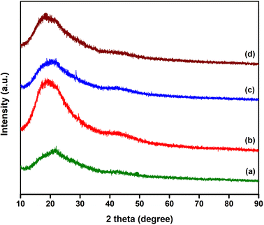
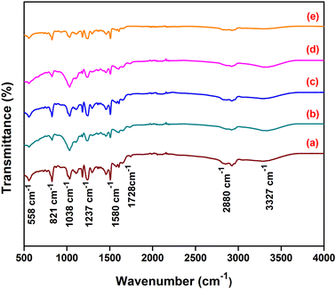
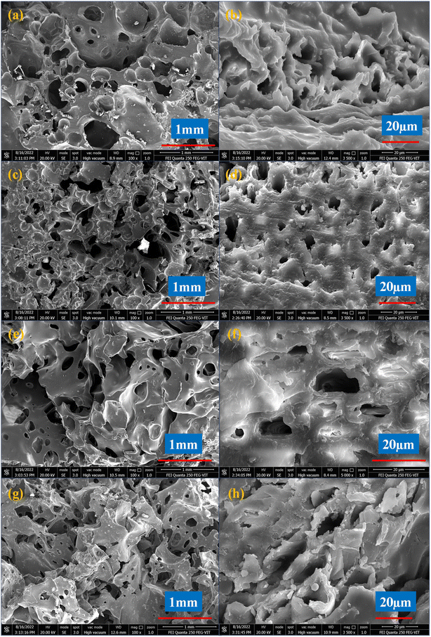
Interfacial evaporation is the technology of localizing heat energy at the air–water interface and is used for getting potable water from salty or seawater effectively. In this work, we introduce a novel interfacial evaporator by blending different weight ratios of waste sawdust (1 g, 2 g, 3 g and 4 g) with bisphenol-A epoxy resin (LY556) and triethyltetramine hardener (HY951). The fabricated epoxy hardener sawdust (EHS) composite material was subjected to various characterizations for the possibility of using it in solar steam generation. Consequently, EHS displayed high light absorption, amorphous structure, functional groups, and large number of pores. The main objective of the study was to investigate interfacial solar steam generation with and without interfacial evaporators (EHS-1g, EHS-2g, EHS-3g, and EHS-4g) under indoor conditions. The maximum mass loss of water, evaporation rate and evaporation efficiency were found to be 4.5 g, 1.398 kg m−2 h−1, and 92.99%, respectively, for the EHS-4g evaporator. The salinity of the distilled condensed water was measured and was below the WHO standards. The results are due to (i) the large number of cross-linked porous structures used to permeate water at the evaporative surface by capillary action, (ii) low thermal conductivity of the composite that offers an efficient broad and strong light absorption, and (iii) existence of a larger hydraulic diameter and small tortuosity of pores, which reduces the salt ion penetration distance and dispatch back to bulk water.
Introduction
Potable water is essential for all people to live on Earth. It is unfortunate that the amount of fresh water for every individual keeps decreasing due to the fast growth of industrialisation, population, modern society and natural droughts. It has been reported that almost 29% people are unable to obtain pure water and 6% deaths occur in developing countries from drinking impure water. Although many natural water resources are available globally, they are not directly utilized for drinking due to the presence of pesticides, suspended particles, anionic pollutants, colloidal materials, heavy metals, non-metallic substances, microorganisms, and various dissolved metallic substances. Furthermore, the natural water resources may be polluted and everyone will necessitate a substitute source to acquire water and fulfill their basic requirements by 2050.1–5To rectify this omnipresent issue, many new technologies such as multi-effect distillation technology, flash distillation, and reverse osmosis have been developed to obtain pure drinking water. However, salt mitigation of seawater affects the efficiency and life of the equipment. In addition, membrane fouling and high energy demand are long-term problems in the reverse osmosis system. Reverse osmosis and multi-effect distillation also consume significant power input of about 5 and 8 kW h m−2, respectively. Therefore, they are unsuitable for offshore regions, villages, and remote off-grid areas. Thus, it is time to seek a sustainable desalination technology that is low cost, scalable, portable and achieves peak output with low energy input.6–9 Solar energy is one of the indispensable, sustainable and renewable energy technologies. Currently, solar energy is employed in the photochemical, photovoltaic and photothermal fields. Photothermal processes convert light to heat through reflection, absorption and high temperature. Solar thermal distillation is one of the best conventional methods for steam generation. Here, solar light is directly used to heat water, which gets evaporated and is collected by the condensation process.10–12
In recent years, interfacial solar steam generation (ISSG) has emerged as a potential and environmentally friendly solution to the problem of a lack of water among a variety of constantly developing technologies. It is the process of absorbing a large amount of solar energy using carbon-based materials, porous polymers, metal nanoparticles, black semiconductors and other absorber materials.13,14 The vapour is formed on the interface surface by highly localising the solar energy where bulk water heating is hindered. The total amount of incident light is utilized to heat the top surface of the substrate. So, the unwanted heat loss is minimized. At the beginning of World War II, U.S. military pilots and sailors used this technology to produce drinking water in ocean areas. Here, the first aid kit was fabricated using a black wet cotton towel and plastic bag. Later, the process was categorized as interfacial solar steam generation.15,16 The first interfacial solar evaporator was made of a hydrophilic porous structure substrate that assisted in transporting water, while it floated on the water surface.17 Li et al.18 used rice straw-based membranes to investigate the performance, and found a maximum of 75.8% evaporation efficiency. Liu et al.19 experimented with a carbonised sawdust-based evaporator in ISSG, and obtained an efficiency of about 77.64%. Xue et al.20 conducted ISSG using treated wood with fire. They reported an evaporation efficiency of 72% at 1 kW m−2. On the other hand, Dandan et al.21 investigated Ni-NiOx/Ni foam in ISSG and attained 1.41 kg m−2 h−1 in evaporation rate. Wei H. et al.22 showed an evaporation rate of 1.73 kg m−2 h−1 with CuxS/Cu foam. Over the last decade, different substrates like aerogels, paper, gauze, wood, and sawdust have been introduced in ISSG due to their good insulating property, biodegradability and low cost.23 Among all, wood has better properties like low thermal conductivity, accessibility and high water transfer. The structure of the interfacial evaporator also plays a vital role in evaporation efficiency. This method can be applied in various applications, such as sewage disposal, oil–water separation, electricity generation, and waste sterilisation.20
Currently, blending natural fibres into polymers is widely used for various applications like building, shipping, and packing industries. Due to their unique properties such as being lightweight, contributing less pollution and having a higher fibre content, natural fibres are chosen rather than synthetic fibres. In the past few years, natural fibres like sawdust, teak, hemp, jute, cotton, sisal, pine, flax and broom have been incorporated with polyolefins, polystyrene and epoxy resins to fabricate thermoset and thermoplastic matrices.24 Natural biopolymers like polydopamine and melanin-based bio polymers have also been used in ISSG due to their effective hydrophilicity, non-toxic, biodegradability and noble photothermal conversion efficiency.25 Open-celled microcellular polymer materials have a large number of similar-sized microporous structures that allow for particles, fluids, gas and sound to pass through them, and are further used in many applications.26 Huang et al.27 fabricated polystyrene/lignocelluloses skeleton-based membranes and found an evaporation efficiency of 85.5% under 1.5 sun illuminations. Li et al.28 obtained an evaporation efficiency of 77% under 1 sun irradiation when PDA-coated raw wood was used as an evaporator. Juan et al.29 experimentally investigated the ISSG process using an attapulgite/poly acrylamide composite. They found an evaporation efficiency of 85%. Lifang et al.30 fabricated a 2D electrospun nanofibrous membrane by blending polyacrylonitrile and bisphenol epoxy resin. They showed that the fabricated membrane has high porosity and can be used in ISSG, resulting in an evaporation rate of 2.70 kg m−2 h−1. Liu et al.31 experimented with the ISSG process using a membrane (poly(3,4-ethylenedioxythiophene) and polyetheramide-modified cation exchange resin) and a maximum evaporation rate of 1.42 kg m−2 per hour was achieved.
It was found from the literature that a limited number of research works on polymer-based composite have experimented with solar steam generation. Most of the research works followed the chemical blowing method for the preparation of polymer composites. It is also a time-consuming and costly process. The novelty of the present work is to prepare a low-cost, facile and self-floating salt rejection epoxy/hardener/sawdust polymer composite as an interfacial evaporator for enhancing the performance of solar steam generation. The fabricated composite has a hierarchically cross-linked porous structure and more active sites that facilitate fast water permeation.
The present investigation aimed to fabricate interfacial evaporators with different weight ratios of sawdust and epoxy resin. These interfacial evaporators were then used in the interfacial steam generation process at indoor conditions. The champion device resulted in a maximum mass loss of 4.5 g, evaporation rate of 1.39 kg m−2 h−1 and solar thermal efficiency of 92.99% under 1 sun illumination. Furthermore, the concentration of heavy metal ions was reduced considerably below WHO standards. As a result, it has been demonstrated that the interfacial evaporators show significant promise for producing solar vapour and may be useful for various sun-heating applications, including solar distillation, power generation and sterilisation.
Experimental section
Materials
Coconut tree sawdust was collected from the local woodcutter shop and dried in sunlight to remove the moisture content. Epoxy resin (bisphenol-A) – LY 556 and Aradur Hardener curing agent (triethyltetramine) HY - 951 were purchased from the market. Seawater was collected from Marina Beach, Chennai, India (latitude-130 03′ 15.05′′ N, and longitude-800 17′ 1.25′′ E). Stereolithography (SLA) of 3D printing filament with 1.75 mm in diameter was purchased from Sigma-Aldrich. Sawdust was chosen as the filler material because of its low thermal conductivity nature, non-toxicity, low cost and waste product.Fabrication of circular-type epoxy/hardener/sawdust composite
In this study, a 2![[thin space (1/6-em)]](https://www.rsc.org/images/entities/char_2009.gif) :
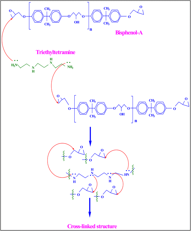
:![[thin space (1/6-em)]](https://www.rsc.org/images/entities/char_2009.gif) 1 ratio of epoxy resin and hardener was taken to fabricate the polymer-based interfacial evaporator. First, a polyethene cup was taken and cleaned with distilled water to remove impurities and dust. With the help of disuse paper, the moisture content was removed from the cup. Next, epoxy resin was poured into the cup and added with 1 g of sawdust. The hardener was added and stirred for about 2 min using a glass stirring rod. Then, the mixture was kept in an ideal place for 10 min. The thickness and size of the composites were swelled due to exothermic reactions. The mechanism of curing was mainly due to the substitution reaction of the hardener-HY 951. The presence of nucleophilic NH2 in the hardener attacked the electrophilic carbon of the C–O bond of the epoxide ring of bisphenol A-LY 556, which led to breaking the chain and resulted in ring opening. This process continued until the hierarchically cross-linked structure formation occurred. The chemical and cross-linked structure of the composite is illustrated in Fig. 1. Here, the molecules of the compositions react and a slight increase in temperature was observed. During this process, the air was mechanically whipped or beaten into the epoxy/hardener/sawdust mixture and formed micro and macro froths. The polymerization of the resin mixture resulted in irregular pores, like elliptical and spherical pores, which were connected by pore throats. After reducing the temperature of the composite, it was taken out from the polyethene cup. Then, the required size of the composite (Dia: 65 mm and thickness: 10 mm) was cut and used for the interfacial solar steam generation process. It was named as epoxy/hardener/sawdust-1 g composite (EHS-1g). In order to hold the developed composite material, a 3D-printed ring was fabricated using SLA material. The diameter and thickness of the 3D-printed ring were 65 mm and 7.5 mm, respectively.
1 ratio of epoxy resin and hardener was taken to fabricate the polymer-based interfacial evaporator. First, a polyethene cup was taken and cleaned with distilled water to remove impurities and dust. With the help of disuse paper, the moisture content was removed from the cup. Next, epoxy resin was poured into the cup and added with 1 g of sawdust. The hardener was added and stirred for about 2 min using a glass stirring rod. Then, the mixture was kept in an ideal place for 10 min. The thickness and size of the composites were swelled due to exothermic reactions. The mechanism of curing was mainly due to the substitution reaction of the hardener-HY 951. The presence of nucleophilic NH2 in the hardener attacked the electrophilic carbon of the C–O bond of the epoxide ring of bisphenol A-LY 556, which led to breaking the chain and resulted in ring opening. This process continued until the hierarchically cross-linked structure formation occurred. The chemical and cross-linked structure of the composite is illustrated in Fig. 1. Here, the molecules of the compositions react and a slight increase in temperature was observed. During this process, the air was mechanically whipped or beaten into the epoxy/hardener/sawdust mixture and formed micro and macro froths. The polymerization of the resin mixture resulted in irregular pores, like elliptical and spherical pores, which were connected by pore throats. After reducing the temperature of the composite, it was taken out from the polyethene cup. Then, the required size of the composite (Dia: 65 mm and thickness: 10 mm) was cut and used for the interfacial solar steam generation process. It was named as epoxy/hardener/sawdust-1 g composite (EHS-1g). In order to hold the developed composite material, a 3D-printed ring was fabricated using SLA material. The diameter and thickness of the 3D-printed ring were 65 mm and 7.5 mm, respectively.
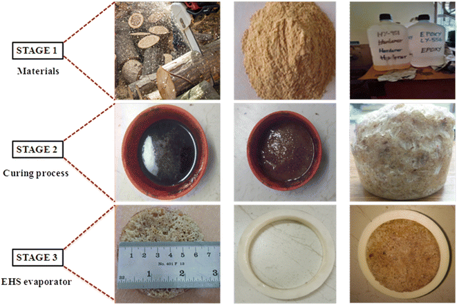
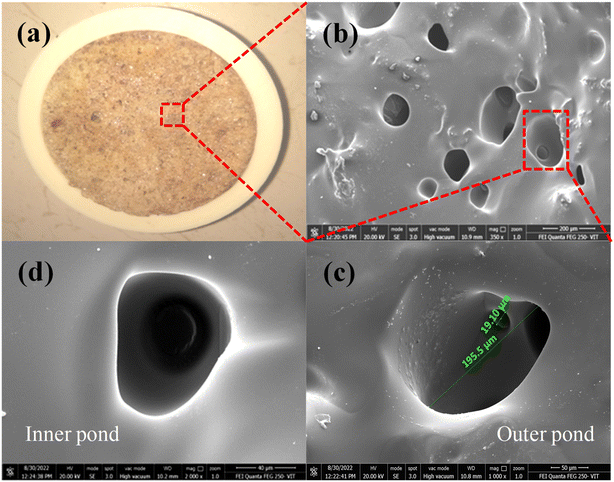
Similarly, the same quantity of epoxy/hardener was combined with sawdust at various weight ratios (2 g, 3 g, and 4 g) to develop the different composites, which were named as EHS-2g, EHS-3g and EHS-4g, respectively. The fabrication process of the epoxy/hardener/sawdust composites is shown in Fig. 2. During the above processes, we identified that the increase in the amount of sawdust reduced the formation of froths and the size of pores.
Steam generation experimental setup
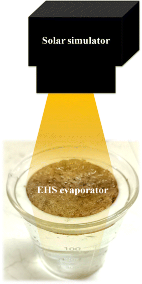
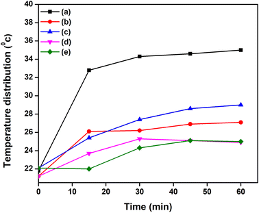
The solar simulator-based steam generation process is shown in Fig. 3. Here, the solar simulator was placed on top of the bulk seawater surface. The incident light intensity was measured by a pyranometer and maintained at 1 sun illumination. The steam generation process was conducted without and with (EHS-1g, EHS-2g, EHS-3g, and EHS-4g) evaporated medium. When the EHS (epoxy/hardener/sawdust) evaporator was floated on the water surface, it acted as a water transporting medium for steam generation. Temperature distribution from the evaporator surface to water was recorded using a thermal image camera. The steam generation process was executed for 60 min, and the mass loss of water was noted every 5 min using a weighing machine.Characterization
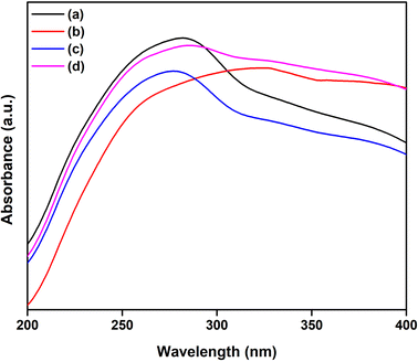
The 3D printing material was developed using a WANHAO Duplicator 4S instrument. A UV-Vis-NIR spectrometer (Jasco V-670) was used to evaluate the light absorption capacity of the prepared materials over the range of 250 to 400 nm. Phase analysis of the EHS evaporator was analysed by X-ray diffraction (XRD) D8 advanced instrument (Make: Bruker-Germany). Functional groups were determined by an attenuated total reflection Fourier transform infrared (ATR-FTIR) spectroscopy instrument (Make: Thermo Fisher Sci., US) in the infrared wavelength region. Field emission scanning electron microscopy (FE-SEM) was used to study the surface morphology of the composite. The thermal conductivity of the sample was estimated using a KD2 Pro instrument (Make: Decagon Device, INC, US). The surface temperature of the evaporator during steam generation was recorded using a thermal image FLIR camera (Model: T1020-12-NIST, India). A Citizen CY 204 (Make: kalpanaTechnolab, India) instrument was used to measure the mass loss of water. The ion concentrations of the impure and collected water were measured by atomic absorption spectroscopy (Model: Varian AA 240, make: SpectraLab scientific Inc, Canada) and flame photometer instruments (Make: Systronics, Model: 128).Results and discussion
Characterizations of the EHS composite
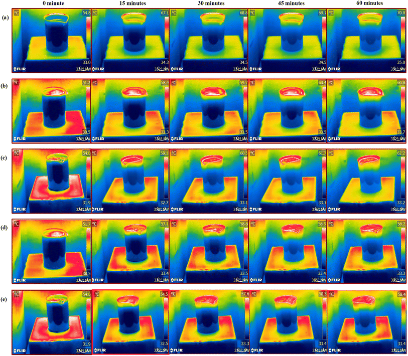 | ||
| Fig. 8 Thermal image analysis: (a) without evaporator, (b) EHS-1g, (c) EHS-2g, (d) EHS-3g and (e) EHS-4g at 0, 15, 30, 45 and 60 min. | ||
 | (1) |
The mass loss, evaporation rate and evaporation efficiency of water without and with interfacial evaporators are shown in Fig. 10a–c. Without an interfacial evaporator, the obtained mass loss, evaporation rate and efficiency of water are 3.6 g, 1.119 kg m−2 h−1 and 74.76%, respectively. In general, the supply of heat input to water is lost by conduction, convection and radiation.39 So, the bulk water heating gives insufficient output. In contrast, the interfacial evaporators (such as EHS-1g, EHS-2g, EHS-3g and EHS-4g) have evaporation rates of 1.181, 1.253, 1.336, and 1.398 kg m−2 h−1, and the corresponding efficiencies are 78.93%, 83.65%, 88.85% and 92.99%, respectively. The obtained results are much higher than that without an interfacial evaporator case. In order to evaluate the repeatability and durability of the EHS-4g evaporator, the experiments were conducted with the existing setup for 15 repetitive cycles. Fig. 10d depicts the evaporation efficiency of the repetitive cycles. It can be seen that the efficiency did not change much in all the cycles, which confirms that the EHS-4g evaporator is highly stable. The mass loss of water of EHS-1g, EHS-2g, EHS-3g and EHS-4g is 3.8, 4.0, 4.3 and 4.5 g, respectively. The mass loss of water increases with the addition of sawdust into the epoxy resin. Here, EHS has numerous pores and each pore is interconnected with the water channel. With the presence of small cavities in this channel, water refilling at the evaporation surface is achieved quickly. The low thermal conductivity of the interfacial evaporator suppresses the heat losses and avoids heat distribution to the bulk fluid. It promotes decreasing losses via conduction, convection and radiation. So, the total amount of heat is utilized for heating the top surface of the water.
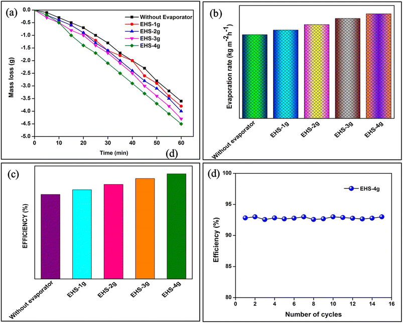 | ||
| Fig. 10 Steam generation analysis of (a) mass loss, (b) evaporation rate, (c) efficiency and (d) solar steam generation efficiency of the EHS-4g for 15 cycles. | ||
Salt accumulation in the evaporation process is the major concern for the ISSG process, as it blocks the water transport channel. This further reduces the mass loss, evaporation rate and efficiency. Fig. 11 illustrates the prevention of salt accumulation at the evaporative surface of EHS-4g composite before (dry) and after (wet) steam generation process. It can be seen that there is no salt accumulated on the evaporative surface for after steam generation process.
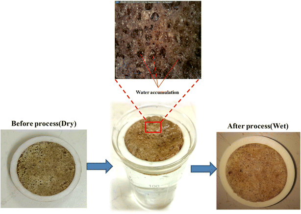 | ||
| Fig. 11 Prevention of salt accumulation at the evaporative surface of the EHS-4g composite – before and after the steam generation process. | ||
Here, the high porosity and small tortuosity effect of the evaporator help to increase the salt interchange of bulk water and supply water continuously to the evaporation surface through plentiful water channels. Due to the larger size of the pores, the hydraulic diameter is increased, which aids in supplying more amounts of water flows in a single channel. Hence, salt growth is restricted and the salt emigrate rate at the evaporative surface is reduced.
We suggest that the following may be the reasons for obtaining the enhanced steam generation: (i) the EHS-4g composite material absorbs a greater amount of solar irradiation and converts heat energy effectively; (ii) as the composite material has a good number of pores, it aids in achieving good capillary action and water refilling at the evaporative surface productively; (iii) the fabricated composite material develops an indirect water path, which gives effective heat treatment at the air–water interface and encouraging interfacial solar steam generation; (iv) As the EHS evaporator has low thermal conductivity (0.095 W mK−1), it restricts the heating of the bulk fluid.
Water quality testing
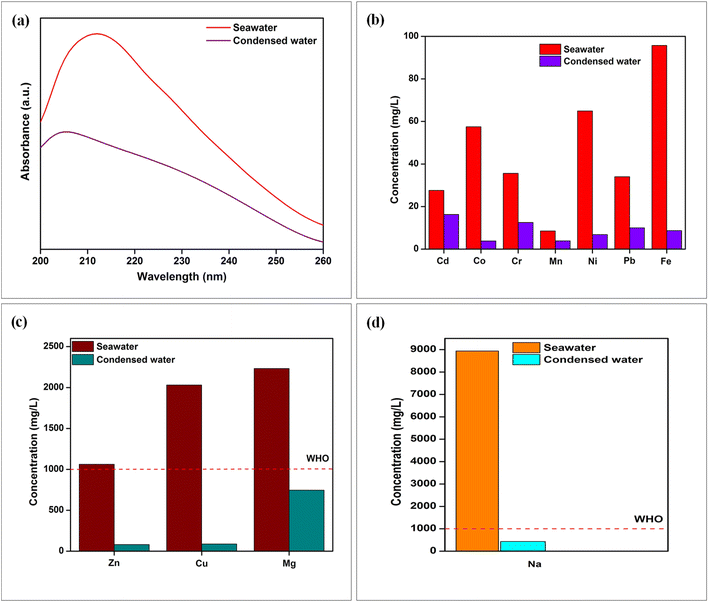
The ISSG has the ability to produce clean and potable water, leaving behind inorganic heavy metals like Mg, Cr, Mn, Ni, Pb, Cd, Co, Fe, Zn, Cu, and Na. The presence of heavy metals in the water sample was examined using an atomic absorption spectroscopy instrument (Make: Varian Inc, India; Model: AA 240). The sodium ion was measured using a flame photometer (Make: Systronics, Model: 128) instrument. Fig. 12b–d depicts the sample of seawater and condensed water. As observed from Fig. 12b–d, the sample of seawater has a higher heavy metal concentration above the drinking water standard, as suggested by WHO. As a result, Cd, Co, Cr, Mn, Ni, Pb, Fe, Zn, Cu, Mg and Na ions concentrations are reduced by orders of magnitude to 16.3, 3.8, 12.5, 3.9, 6.85, 10, 8.67, 80.48, 88.1, 745 and 433 mg L−1, respectively, in the condensed water. It was observed that the amount of ion concentration in the evaporated water has reduced considerably, and meets the safe-drinking water levels provided by the WHO standard.31,42 We suggest the reason for the decreasing ion concentrations as follows: The fabricated composite material has twists, bends and a crooked porous structure. When the water passes through these structures, the tortuosity effect arises. Therefore, the movement of heavy metal ions is hindered during evaporation by a microporous interfacial evaporating medium. Because the size of the salt ions is larger than that of water molecules, the penetration of salt ions is trapped on the evaporative medium. Numerous pores on the interfacial medium generated a larger hydraulic diameter, which increases the amount of water permeation from the bottom to the evaporative surface. So, the salt ions emigration distance is reduced and goes back to the bottom water. This prevents salt accumulation at the evaporative surface, while using high-salinity of water. For those above reasons, the EHS-4g evaporator offers efficient antifouling capability for long term.
Conclusion
In summary, the fabricated brand-new epoxy/hardener/sawdust (EHS-1g, EHS-2g, EHS-3g and EHS-4g) composite-based interfacial evaporators have been tested for the efficient and stable solar-driven interfacial steam generation process. This study experimentally proved that the EHS-4g composite evaporator has small cavities in the water transporting channels, which aids the replacement of water at the evaporation surface effectively. Large hydraulic diameters and small tortuosity of pores hinder salt accumulation at the top surface and balance the water transportation. The low thermal conductivity of the interfacial evaporators also prohibits the heat distribution from the radiated surface to bulk water. The EHS-4g composite evaporators have the antifouling capability, and provide quick, affordable manufacturing and scalability that offer promising strategies for sustainable freshwater production from seawater, especially water with high salinity. The EHS-4g composite evaporator showed excellent solar vapour generation potential, and is probably suitable for other applications, such as sterilizing, desalination and distillation. In the future, we have a plan to coat eco-friendly nanomaterials over the evaporative surface of the EHS-4g composite evaporator for highly efficient solar steam generation.Conflicts of interest
There are no conflicts to declare.References
- J. O. Duruibe, M. O. C. Ogwuegbu and J. N. Egwurugwu, Int. J. Phys. Sci., 2007, 2(5), 112–118 Search PubMed
.
- B. C. Kross, J. Prev. Med., 2002, 10(1), 3–10 Search PubMed
.
- A. K. Kaviti, A. S. Ram, A. Aruna Kumari and S. Hussain, Mater. Today: Proc., 2021, 44, 282–288 CAS
.
- S. P. Suriyaraj and R. Selvakumar, RSC Adv., 2016, 6(13), 10565–10583 RSC
.
- P. K. Singh, P. K. S. Rathore and S. K. Shukla, Int. J. Energy Res., 2022, 46(2), 937–951 CrossRef CAS
.
- C. Zhang, H. Q. Liang, Z. K. Xu and Z. Wang, Adv. Sci., 2019, 6(18), 1970111 CrossRef
.
- L. Li, T. Hu, A. Li and J. Zhang, Chem. Eng. J., 2021, 422, 129998 CrossRef
.
- S. Tiwari and P. K. S. Rathore, Mater. Today: Proc., 2022 DOI:10.1016/j.matpr.2022.08.048
.
- V. K. Chauhan, S. K. Shukla, J. V. Tirkey and P. K. S. Rathore, J. Cleaner Prod., 2021, 284, 124719 CrossRef
.
- H. M. Qiblawey and F. Banat, J. Environ. Prot., 2008, 220(1–3), 633–644 CAS
.
- Z. Li, C. Wang, T. Lei, H. Ma, J. Su, S. Ling and W. Wang, Adv. Sustainable Syst., 2019, 3(4), 1800144 CrossRef
.
- V. K. Chauhan, S. K. Shukla and P. K. S. Rathore, J. Energy Storage, 2021, 47, 103578 CrossRef
.
- K. Xu, C. Wang, Z. Li, S. Wu and J. Wang, Adv. Funct. Mater., 2021, 31(8), 1–26 CrossRef
.
- Z. Wang, M. Han, F. He, S. Peng, S. B. Darling and Y. Li, Nano Energy, 2020, 74, 104886 CrossRef CAS
.
- F. Tao, Y. Zhang, K. Yin, S. Cao, X. Chang, Y. Lei, D. Wang, R. Fan, L. Dong, Y. Yin and X. Chen, Sustainable Energy Fuels, 2018, 2(12), 2762–2769 RSC
.
- X. Luo, J. Shi, C. Zhao, Z. Luo, X. Gu and H. Bao, Appl. Energy, 2021, 302, 117581 CrossRef
.
- H. Ghasemi, N. George, A. M. Marconnet, J. Loomis, S. Yerci, N. Miljkovic and G. Chen, Nat. Commun., 2014, 5, 1–7 Search PubMed
.
- Q. Fang, T. Li, Z. Chen, H. Lin, P. Wang and F. Liu, ACS Appl. Mater. Interfaces, 2019, 11(11), 10672–10679 CrossRef CAS PubMed
.
- S. Liu, C. Huang, X. Luo and C. Guo, Appl. Energy, 2019, 239, 504–513 CrossRef
.
- G. Xue, ACS Appl. Mater. Interfaces, 2017, 9(17), 15052–15057 CrossRef CAS PubMed
.
- D. Wu, D. Qu, W. Jiang, G. Chen, L. An, C. Zhuang and Z. Sun, J. Mater. Chem. A, 2019, 7(14), 8485–8490 RSC
.
- W. Huang, P. Su, Y. Cao, C. Li, D. Chen, X. Tian, Y. Su, B. Qiao, J. Tu and X. Wang, Nano Energy, 2020, 69, 104465 CrossRef CAS
.
- M. M. Ghafurian, M. R. Malmir, Z. Akbari, M. Vafaei, H. Niazmand, E. K. Goharshadi, A. Ebrahimi and O. Mahian, Energy, 2022, 244, 123146 CrossRef CAS
.
- R. Chandra Mohapatra, A. Mishra and B. Bhushan Choudhury, Am. J. Mech. Eng., 2014, 2(4), 114–119 CrossRef
.
- X. Xu, S. Ozden, N. Bizmark, C. B. Arnold, S. S. Datta and R. D. Priestley, Adv. Mater., 2021, 33(18), 1–9 Search PubMed
.
- D. Doermann and J. F. Sacadura, J. Heat Transfer, 1996, 118(1), 88–93 CrossRef
.
- Q. Huang, C. Du, C. Guo, C. Huang and X. Wang, Appl. Therm. Eng., 2021, 187, 116515 CrossRef CAS
.
- Y. Zou, P. Yang, L. Yang, N. Li, G. Duan, X. Liu and Y. Li, Polymers, 2021, 217, 123464 CrossRef CAS
.
- J. Jia, W. Liang, H. Sun, Z. Zhu, C. Wang and A. Li, Chem. Eng. J., 2019, 361, 999–1006 CrossRef CAS
.
- L. Qiao, N. Li, L. Luo, J. He, Y. Lin, J. Li, L. Yu, C. Guo, P. Murto and X. Xu, J. Mater. Chem. A, 2021, 9(15), 9692–9705 RSC
.
- C. Liu, Y. Peng, C. Cai, J. Zhang and X. Zhao, J. Environ. Chem. Eng., 2021, 9(4), 105272 CrossRef CAS
.
- S. M. Moosavi Nejad, M. Madhoushi, D. Rasouli and M. Vakili, J. Wood For. Sci. Technol., 2017, 23, 313–328 Search PubMed
.
- H. Alhumade, H. Rezk, A. M. Nassef and M. Al-Dhaifallah, IEEE Access, 2019, 7, 100899–100909 Search PubMed
.
-
(a) N. U. Rahman, I. Ullah, S. Alam, M. S. Khan, L. A. Shah, I. Zekker, J. Burlakovs, A. Kallistova, N. Pimenov, Z. Vincevica-Gaile and Y. Jani, Water, 2021, 13(15), 2136 CrossRef CAS
; (b) H. Yang, Y. Wang, Z. Liu, D. Liang, F. Liu, W. Zhang, X. Di, C. Wang, S. H. Ho and W. H. Chen, J. Bioresour. Bioprod., 2017, 4, 1–2 CrossRef PubMed
.
- S. Yu, J. W. Lee, T. H. Han, C. Park, Y. Kwon, S. M. Hong and C. M. Koo, ACS Appl. Mater. Interfaces, 2013, 5(22), 11618–11622 CrossRef CAS PubMed
.
- N. Kumari, M. Paswan and K. Prasad, Mater. Today: Proc., 2021, 49, 1719–1722 Search PubMed
.
- Y. Xu, J. Yin, J. Wang and X. Wang, Rev. Adv. Mater. Sci., 2019, 58(1), 226–247 Search PubMed
.
- S. L. Wu, H. Chen, H. L. Wang, X. Chen, H. C. Yang and S. B. Darling, Environ. Sci.: Water Res. Technol., 2021, 7(1), 24–39 RSC
.
- W. G. S. Martin, Environ. Sci. Technol., 2001, 15, 1–6 Search PubMed
.
- J. Hussain, I. Husain, M. Arif and N. Gupta, Appl. Water Sci., 2017, 7(8), 4539–4548 CrossRef CAS
.
- M. Kumar, S. Singh and R. K. Mahajan, Environ. Monit. Assess., 2006, 112(1–3), 283–292 CrossRef CAS PubMed
.
- H. Li, D. Jia, M. Ding, L. Zhou, K. Wang, J. Liu, C. Y. Liu and C. Li, Sol. RRL, 2021, 5(8), 1–11 Search PubMed
.
| This journal is © The Royal Society of Chemistry 2023 |

