 Open Access Article
Enhancing the stability and efficiency of MAPbI3 perovskite solar cells by theophylline-BF4− alkaloid derivatives, a theoretical-experimental approach†
Edgar González-Juárez‡
a,
Arián Espinosa-Roa‡ *b,
Alejandra T. Cadillo-Martínezc,
Andrés M. Garay-Tapia
 c,
Miguel A. Amado-Briseñobd,
Rosa A. Vázquez-Garcíad,
Alejandro Valdez-Calderone,
Jayaramakrishnan Velusamyf and
Eduardo M. Sanchez
 a
a
aUniversidad Autónoma de Nuevo León, UANL, Facultad de Ciencias Químicas (FCQ), Av. Universidad s/n, Cd. Universitaria, San Nicolás de los Garza, Nuevo León C.P. 66450, Mexico
bCONACyT-Centro de Investigación en Química Aplicada (CIQA), Unidad Monterrey, Alianza Sur 204, PIIT, Apodaca, Nuevo León C.P. 66628, Mexico
cCentro de Investigación en Materiales Avanzados S.C. (CIMAV), Unidad Monterrey, Alianza Norte 202, PIIT, Apodaca, Nuevo León C.P. 66628, Mexico
dUniversidad Autónoma del Estado de Hidalgo (UAEH). Área Académica de Ciencias de la Tierra y Materiales, Carretera Pachuca-Tulancingo Km. 4.5., Ciudad del Conocimiento, Mineral de la Reforma, Hgo C.P. 42184, Mexico
eUniversidad Tecnológica de la Zona Metropolitana del Valle de México, Blvd. Miguel Hidalgo y Costilla 5, Los Héroes de Tizayuca, Tizayuca, Hgo C.P. 43816, Mexico
fChemical Engineering and Biotechnology, University of Cambridge, Philippa Fawcett Drive, Cambridge, CB3 0AS, UK. E-mail: arian.espinosa@ciqa.edu.mx
First published on 8th February 2023
Abstract
Perovskite solar cells (PSCs) are an evolving photovoltaic field with the potential to disrupt the established silicon solar cell market. However, the presence of many transport barriers and defect trap states at the interfaces and grain boundaries has negative effects on PSCs; it decreases their efficiency and stability. The purpose of this work was to investigate the effects on efficiency and stability achieved by quaternary theophylline additives in MAPbI3 PSCs with the structure FTO/TiO2/perovskite/spiro-OMeTAD/Ag. The X-ray photoelectron spectroscopy (XPS) and theoretical calculation strategies were applied to study the additive's interaction in the layer. The tetrafluoroborinated additive results in an increase in device current density (JSC) (23.99 mA cm−1), fill factor (FF) (65.7%), and open-circuit voltage (VOC) (0.95 V), leading to significant improvement of the power conversion efficiency (PCE) to 15.04% compared to control devices (13.6%). Notably, films exposed to controlled humidity of 30% using the tetrafluoroborinated additive maintained their stability for more than 600 hours (h), while the control films were stable for less than 240 hours (h).
1 Introduction
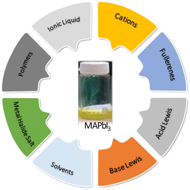
It is well known that crystalline silicon-based solar cells dominate the alternative energy market with respect to the photovoltaic industry; however, manufacturing costs offer the opportunity to develop new solar cell technologies that can be more economical and efficient. Surprisingly, perovskite solar cells (PSCs) have achieved a certified power conversion efficiency (PCE) of 25.2% in just eleven years after the first device was manufactured in 2009.1,2 MAPbI3 perovskite has been one of the most promising types as a third-generation photovoltaic device. Significantly, the active layer interaction gained much attention from researchers. The crystalline growth of MAPbI3 perovskite thin films is also fast, and a high-temperature range (100–150 °C) is required for crystallization, so a wide variety of defects is unavoidable.3–5 Perovskite thin films fabricated by solution processing often exhibit interstitial defects, substitutions, and vacancies, which act as charge recombination centers, resulting in loss of device efficiency.6–8 However, the defects9 are responsible for hysteresis,10 non-radiative recombination,11 charge trapping,12 charge scattering13 and ionic migration effects14 in the MAPbI3 film. A different study has shown that the performance of perovskite solar cells is highly dependent on the microstructure of the perovskite layer, as well as on the interfacial properties of the devices.15 Consequently, prolonged exposure of devices to moisture results in critical degradation in the photovoltaic performance of the devices.16,17Recently, the scientific community has introduced a new strategy entitled additive engineering involving the incorporation of specific materials (Fig. 1). A variety of materials have been employed to passivate perovskite thin films, including low-dimensional perovskites,18–20 alkaline halides,21,22 polymers,23–27 inorganic nanocrystals,28–30 small organic molecules,31–35 organic halide salts,36–38 amine based organic materials,39–41 phosphonium halides.42
In addition, the use of organic compounds and their derivatives as additives in the passivation of perovskite solar cells has been widely studied, which is interesting considering their wide availability.43,44 Among several examples of natural derivatives employed, Yang and co-workers first reported using the alkaloid caffeine in solar cell passivation.45 Caffeine showed a strong interaction with Pb2+ ions enhancing crystallization, generating devices stable for more than 1500 hours (h) and high efficiencies (19.8%). Wang et al. reported the use of caffeine, theophylline and theobromine in perovskite solar cells. They found that theophylline improved the efficiency and stability of the devices than the other two derivatives.46 The mode by which these additives function is through interactions of the carbonyl groups with the lead ions, promoting better crystallization and thus less ion migration. The derivatives, being non-volatile, interact with the perovskite and prevent its thermal degradation. Recently, Zhang et al.47, used aminophylline (theophylline-ethylenediamine derivative) which promotes good crystallization suppresses ion migration through interactions and generates good structural stability.
The use of pseudohalides, such as tetrafluoroborate (BF4−), hexafluorophosphate (PF6−), and thiocyanate (SCN−), have also significantly improved efficiencies because they have similar chemical properties and ionic radius as iodide. Especially, the use of BF4− has also been widely studied as a counterion of additives against defects, this process has been explained in the literature, in its implications in increasing conductivity48 and its capability to replace any part of the perovskite iodides, or even passivating the surface avoiding the anionic migration.49 It has also been used as a counterion to methylammonium as an additive, decreasing charge recombination.50,51 In the literature, there are several examples of organic additives with BF4− as an anion that report benefits in efficiency and stability.52–54
In the present investigation, we report the incorporation of new additives derived from theophylline quaternized with chloride and tetrafluoroborate anions in MAPbI3 perovskite solar cells. The strategies implemented in this work have increase the stability and efficiency of MAPbI3 perovskite solar cells through better crystallization by interactions of the charged alkaloid and the anions by decreasing deep trap states. The fabricated devices increasing their performance and extending the stability of the films generated with this additive exposed for 720 h at a relative humidity of 30%.
2 Experimental
2.1 Materials
All the chemicals were used as received, including titanium diisopropoxide bis(acetylacetonate) (75 wt% in isopropanol, Sigma-Aldrich), 1-butanol (99.8%, Sigma-Aldrich), titanium oxide (TiO2) paste (Dyesol 18NR-T), PbI2 (99.9983%, Sigma-Aldrich), CH3NH3I(99.9%, Lumtec Sci Tech.), N,N-dimethylformamide (DMF, anhydrous 99.5%, Sigma-Aldrich), lithium bis(trifluoromethylsulfonyl)imide (Li-TFSI, Sigma-Aldrich), spiro-MeOTAD (99%, Shenzhen Feiming), chlorobenzene, acetone, ethanol, acetonitrile (SigmaAldrich).2.2 Characterization and measurement
FTIR spectrum was measured using an interspec 200-X spectrometer on KBr pellets. Bruker Avance III of 500 MHz was used for NMR spectral analysis. The chemical shifts (δ) are reported in ppm and the spectra were obtained in CDCl3 and DMSO-d6. The morphological characteristics of the thin films were observed by scanning electron microscopy (SEM) in a JEOL JCM-6000 and a Hitachi SU-8020. X-ray diffractometer (XRD) was employed to characterize the crystallinity of the films using an XRD Bruker D2 phaser. The UV-vis transmission spectra were characterized using a scientific evolution 300 PL spectrophotometer. The X-ray photoelectron spectroscopy (XPS) measurement were obtained by XPS Escalab 250Xi (Thermofisher).2.3 Synthesis of additives
All the manipulations were carried out under an inert atmosphere, following Schlenk techniques. The solvents employed were used as received. The structures and additives characterization (S1 and S2) can be found in the ESI.†2.4 Perovskite standard solar cell device construction
Fluorine-doped Tin Oxide (FTO) glass was patterned by chemical etching with zinc (Zn) powder and chloride acid (HCl) solution. The etched substrate was then cleaned with hellmanex 2% and ultrasonically cleaned with 2-propanol then deionized water in sequence for 15 minutes, respectively. Afterwards, the substrates were cleaned using O2 plasma for 15 minutes (UVO-Cleaner 18 Jeligth Co). A dense layer of TiO2 was then coated on the substrates by spin coating of titanium diisopropoxide bis(acetylacetone) (75 wt% in isopropanol, Aldrich) diluted in absolute ethanol (v/v, 1/20) at 3000 rpm for 1 minute. The substrates were then heated at 180 °C for 5 minutes followed by annealing at 450 °C for 1 h. A mesoporous layer of TiO2 was then deposited by spin-coating TiO2 paste (Dyesol 18NR-T) diluted in absolute ethanol at a 1![[thin space (1/6-em)]](https://www.rsc.org/images/entities/char_2009.gif) :
:![[thin space (1/6-em)]](https://www.rsc.org/images/entities/char_2009.gif) 12 weight ratio at 5000 rpm for 30 seconds. The substrates were then heated at 180 °C for 5 minutes, followed by annealing at 450 °C for 1 h. For the fabrication of the standard cell, the methodology proposed by Sutanto et al.,55 was employed, using DMF as solvent. Previously prepared solution 1.25 M of PbI2
12 weight ratio at 5000 rpm for 30 seconds. The substrates were then heated at 180 °C for 5 minutes, followed by annealing at 450 °C for 1 h. For the fabrication of the standard cell, the methodology proposed by Sutanto et al.,55 was employed, using DMF as solvent. Previously prepared solution 1.25 M of PbI2![[thin space (1/6-em)]](https://www.rsc.org/images/entities/char_2009.gif) :
:![[thin space (1/6-em)]](https://www.rsc.org/images/entities/char_2009.gif) MAI with a 1
MAI with a 1![[thin space (1/6-em)]](https://www.rsc.org/images/entities/char_2009.gif) :
:![[thin space (1/6-em)]](https://www.rsc.org/images/entities/char_2009.gif) 1 molar ratio and left at 70 °C for 12 h. MAPbI3 solution was deposited by spin-coating on the mesoporous layer of TiO2 at 5000 rpm for 30 s. After 4 s of having started the spinner, 400 μL of chlorobenzene were rapidly added to the substrate. Furthermore, a hole transport material (HTM) of spiro-OMeTAD was spin-coated at 3000 rpm for 30 s from a chlorobenzene solution (79.1 mg in 690 μL) that contained 22 μL of 4-tert-butylpyridine and 15 μL of Li-TFSI (bis(trifluoromethane)sulfonimide lithium salt) from a 500 mg mL−1 stock solution in acetonitrile as dopants. Fig. S7† shows the configuration of the photovoltaic device fabricated in this investigation.
1 molar ratio and left at 70 °C for 12 h. MAPbI3 solution was deposited by spin-coating on the mesoporous layer of TiO2 at 5000 rpm for 30 s. After 4 s of having started the spinner, 400 μL of chlorobenzene were rapidly added to the substrate. Furthermore, a hole transport material (HTM) of spiro-OMeTAD was spin-coated at 3000 rpm for 30 s from a chlorobenzene solution (79.1 mg in 690 μL) that contained 22 μL of 4-tert-butylpyridine and 15 μL of Li-TFSI (bis(trifluoromethane)sulfonimide lithium salt) from a 500 mg mL−1 stock solution in acetonitrile as dopants. Fig. S7† shows the configuration of the photovoltaic device fabricated in this investigation.
The perovskite film was also deposited by spin coating a previously prepared solution of 1.25 M of MAI![[thin space (1/6-em)]](https://www.rsc.org/images/entities/char_2009.gif) :
:![[thin space (1/6-em)]](https://www.rsc.org/images/entities/char_2009.gif) PbI2 with a 1
PbI2 with a 1![[thin space (1/6-em)]](https://www.rsc.org/images/entities/char_2009.gif) :
:![[thin space (1/6-em)]](https://www.rsc.org/images/entities/char_2009.gif) 1 molar relation in a solvent mixture of DMF/DMSO (80
1 molar relation in a solvent mixture of DMF/DMSO (80![[thin space (1/6-em)]](https://www.rsc.org/images/entities/char_2009.gif) :
:![[thin space (1/6-em)]](https://www.rsc.org/images/entities/char_2009.gif) 20 v/v) by a one-step process at 5000 rpm for 30 s. After a 6 s delay of the spin coating process, 650 μL of anhydrous chlorobenzene was added on top of the substrate. Additionally, perovskite thin films were sintered at 100 °C for 10 minutes. HTM (hole transport material, spiro-OMeTAD) was spin-coated at 3000 rpm for 30 s. Finally, an 80 nm thick silver layer was deposited under a high vacuum by evaporation as a counter electrode. To study the effect of MAPbI3 on the photovoltaic device's stability and performance when the theophylline derivatives were incorporated in a different stoichiometric ratio is shown in Table S1.†
20 v/v) by a one-step process at 5000 rpm for 30 s. After a 6 s delay of the spin coating process, 650 μL of anhydrous chlorobenzene was added on top of the substrate. Additionally, perovskite thin films were sintered at 100 °C for 10 minutes. HTM (hole transport material, spiro-OMeTAD) was spin-coated at 3000 rpm for 30 s. Finally, an 80 nm thick silver layer was deposited under a high vacuum by evaporation as a counter electrode. To study the effect of MAPbI3 on the photovoltaic device's stability and performance when the theophylline derivatives were incorporated in a different stoichiometric ratio is shown in Table S1.†
2.5 Photovoltaic characterization
The J–V curves were measured using a solar simulator (Newport, Oriel Instruments, 91160A) with a source meter (Keithley 2400). In addition, a xenon lamp was used as a light source, and it was calibrated using a silicon reference solar cell (Enlitech) to regulate the output power of the lamp to 1000 W m−2. The measurements were performed inside the glove box to protect the cells' stability. The cell area was limited using a metal mask (0.254 cm × 0.254 cm). The active area of the device is 0.065 cm2.2.6 DFT calculations
The VASP package was used for all first-principles calculations.56 The Perdew–Burke–Ernzerhof (PBEsol) generalized gradient approximation (GGA) functional method was used for the exchange-correlation, including a dispersion correction using Grimme's DFT-D3 scheme.57 The interaction of core electrons and valence electrons is treated by the Projected Augmented Wave method (PAW). For the optimization, the cutoff energy of 500 eV was used and geometry optimization calculations involved relaxing the top layers and the anions until the forces on atoms were less than 0.01 eV Å−1 in a, and b directions. A 3 × 3 × 1 Monkhorst Pack k-point grid was used for the relaxation. The surfaces were modeled by a slab consisting of 2 × 2 periodicity in the a–b plane and at least three atomic layers along the c axis, separated by 15 Å of vacuum in the c axis. The molecular graphics viewer VESTA was used to plot the atomic structure and charge densities.583 Results and discussion
3.1 Additive synthesis theophylline hydrochloride (ThPhyl-Cl) and theophylline tetrafluoroborate (ThPhyl-BF4)
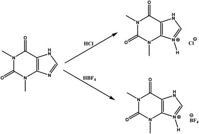
Fig. 2 shows the general scheme for the obtain the additives.The synthesis of the theophylline derivatives has been performed according to the method published by Kennedy et al., 2014.59 In the case of ThPhyl-BF4, it is possible to see the band related to the BF4− anion both by FTIR and in the 11B-NMR spectrum (ESI Fig. S3 to S6†). In 1H-NMR for both ThPhyl-BF4 and ThPhyl-Cl, it is possible to observe that the methyl and N–H chemical shifts are affected by the deprotection of the electron attracting anions.
3.2 Interaction of theophylline derivatives with MAPbI3, XPS
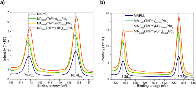
To confirm the interaction between perovskite and theophylline derivatives, XPS analysis of the films was carried out. Fig. 3a shows the 4f orbitals of the lead that were coupled into two signals centered at 138.2 eV and 143.1 eV, corresponding to the interaction of lead with iodine, Pb–I. The second high-resolution 3d spectrum of iodine also confirms the Pb–I interaction with signals centered at 619.2 Ev and 630.8 Ev. These signals are attributed to the presence of [PbI6]−4 units in the perovskite structure. Regarding the other signals, they exhibit a larger shift to higher binding energies with the introduction of the ThPhyl-BF4 additive, which shows, the strong electronic interaction of the carbonyl group of the theophylline derivative with lead as in the case of other previously described additives.47 In the case of ThPhyl-Cl and theophylline there is also an interaction between these additives and the Pb of the perovskite, but the binding energy shifts to lower energies, also previously described in the literature.603.3 Theoretical calculations of interaction of theophylline derivatives with MAPbI3
Theoretical and experimental studies have described the interactions between perovskite and theophylline as an additive. These studies show the strong coordination of the carbonyl groups of theophylline with the Pb on the surface.46 This work offers a notable difference in the photovoltaic parameters when the anion (BF4− and Cl−) varies (Table 1). We perform first-principles calculations to investigate the role of the anion. To understand the surface passivation effects, we first calculate the adsorption energy of the anion/perovskite surface system, which is expressed as:| Eads = Esystem − (Esurface + Eanion) |
| Photovoltaics solar cell | FF (%) | Jsc (mA cm−2) | Voc (mV) | Eff (%) |
|---|---|---|---|---|
| MAPbI3 | 66.20 | 21.60 | 954.00 | 13.60 |
| MA0.995(ThPhy)0.005PbI3 | 65.50 | 21.53 | 949.00 | 13.40 |
| MA0.99(ThPhy)0.01PbI3 | 60.60 | 24.07 | 907.60 | 13.00 |
| MA0.985(ThPhy)0.015PbI3 | 57.00 | 23.02 | 931.10 | 12.20 |
| MA0.995(ThPhyl-BF4)0.005PbI3 | 65.70 | 23.99 | 954.10 | 15.04 |
| MA0.99(ThPhy-BF4)0.01PbI3 | 62.90 | 18.56 | 957.00 | 11.17 |
| MA0.985(ThPhy-BF4)0.015PbI3 | 54.15 | 17.90 | 960.00 | 9.00 |
| MA0.995(ThPhy-Cl)0.005PbI3 | 61.93 | 22.87 | 930.00 | 13.26 |
| MA0.99(ThPhy-Cl)0.01PbI3 | 64.50 | 20.11 | 950.00 | 12.30 |
| MA0.985(ThPhy-Cl)0.015PbI3 | 58.40 | 20.50 | 880.00 | 10.50 |
We find that for BF4− the adsorption energy is more negative compared to Cl−; this indicates more vital interaction of BF4− with the surface (the energies are shown in Fig. 4 a). Coordination with Pb2+ cations could help slow down the growth process leading to better quality perovskite grains, as seen in SEM micrographs (Fig. 8). Charge transfer across the interface was also analyzed, and calculated the charge density difference to visualize charge transfer and the sites of charge accumulation and depletion with the following equation:
| Δρ = ρsystem − (ρsurface + ρanion) |
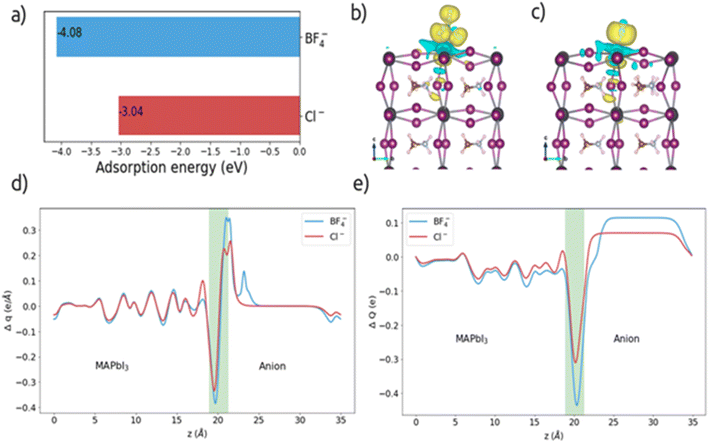 | ||
| Fig. 4 a) Adsorption energy values for BF4− and Cl− anions, (b) and (c) charge density difference, (d) planar charge density difference and (e) charge displacement curve. | ||
For a more detailed analysis of interfacial charge transfer, we have obtained the plane-averaged charge density difference (Δq) and the charge displacement curve (CDC)61,62. These parameters help to understand the charge transfer on the interface. Δq is calculated by integrating Δρ in the xy plane as follows:
The total value of electrons transferred in the perovskite/anion system is determined by the CDC and is given by:
In addition, the CDC informs us of the direction of electron transfer; positive values of CDC at the interface correspond to electrons flowing from left to right and vice versa for negative values. ΔQ is negative in the interface region for both anions (see Fig. 4e), suggesting a transfer of electrons from the perovskite surface side to the anion. From the CDC graph it is obtained that for the BF4− anion, a more significant charge is transferred (0.43e) than for Cl− (0.31e).
To determine the effect of anion deposition on electronic properties, we have calculated the partial density of states (PDOS) and compared it with the density of states of the surface model without anion, see Fig. 5. In the PDOS it is observed that in both cases the valence band (VB) its main contribution is the I orbitals, while the conduction band (CB) is dominated by the Pb orbitals, which is the behavior of MAPbI3 in bulk. However, a displacement of the Pb states (marked in a pink circle) is observed, which causes a change in the bandgap value and causes shallow states in the CB, which could help carrier transport.
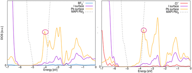 | ||
| Fig. 5 Electronic PDOS on the interface. The zero on the horizontal axis represents the vacuum level and the gray solid line represents the Fermi. | ||
The bandgap value decreases more with the addition of the Cl− anion (1.05 eV) than with the BF4− anion (1.20 eV), whereas the bandgap value of bulk MAPbI3 is reported as 1.6 eV. The decrease in bandgap for Cl− could favor electronic transitions which is reflected in the decay of photovoltaic parameters when this anion is present.
3.4 Stability test of thin films MAPbI3 and MAPbI3![[thin space (1/6-em)]](https://www.rsc.org/images/entities/h3_char_2009.gif) :
:![[thin space (1/6-em)]](https://www.rsc.org/images/entities/h3_char_2009.gif) theophylline derivatives
theophylline derivatives
It is well known that prolonged exposure of the perovskite MAPbI3 is very susceptible to the water molecules generating rapid degradation, which is appreciable on the film by a yellow characteristic of PbI2 that is regenerating in a reversible reaction. Fig. 6 shows the degradation route of MAPbI3 thin film when exposed to ambient.
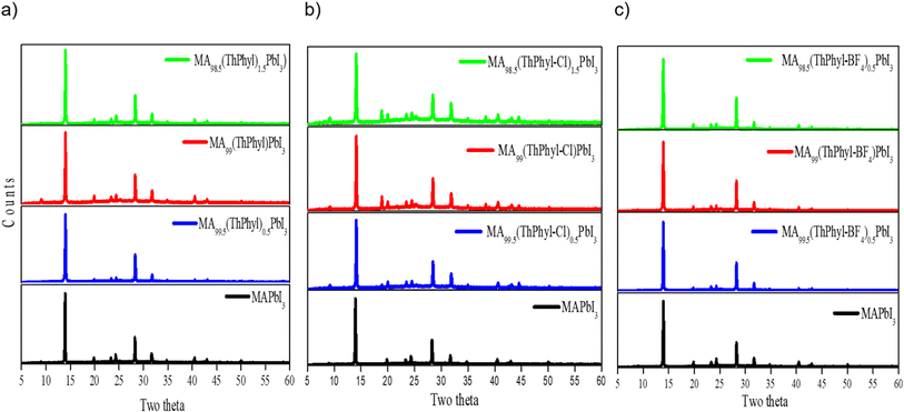
In our case, the degradation of the thin film was monitored by X-ray diffraction (XRD) spectroscopy. Fig. 7 shows the XRD pattern of each of the thin films without and with the different additives. In general, no changes are observed in the X-ray diffractogram pattern of MAPbI3 when the theophylline derivatives are incorporated in different percentages. However, an increase in the intensity of each peak is observed, this can be attributed to a better crystallinity of the perovskite grains, as described in the literature, the interaction of the carbonyl groups of the additive in the three cases may lead to a slower and more orderly crystallization.45,47 Despite not finding the formation of another phase, it is important to note that different studies show the formation of phases due to 2D perovskites generated by the additive at the periphery of MAPbI3 crystals.63
The thin films were fabricated by spin-coating technique, and they have exposed at 30% relative humidity (RH) to study the effect on the stability of MAPbI3 when the theophylline derivatives were incorporated in different percentages.
To follow the degradation of the thin films may consider the tracking of two peaks, mainly the first peak in 2θ = 12.5° is associated with the appearance of precursor PbI2, which indicates the onset and progression of the degradation of perovskite as a function of time. Also, the peak that appears at 2θ = 14.1° which corresponds to MAPbI3, which is associated with the 1 1 0 plane, shows a decrease in intensity during degradation. Fig. S8† shows highlighted diffraction profiles in the range from 2θ = 12°–15°. In general, the diffractograms show an increase in the intensity of the PbI2 peak at different exposure times. MAPbI3 was more susceptible to ambient conditions (Fig. S8a†). However, the incorporation of theophylline derivatives added excellent stability to MAPbI3, especially in the MA0.995(ThPhy-BF4)0.005PbI3 film in which PbI2 peak formed was unobserved for 600 h (Fig. S8c†). The film made with MA0.995(ThPhy)0.005PbI3 began to degrade at 720 h, while MA0.995(ThPhy-Cl)0.005PbI3 started to degrade at approximately 240 h. It is well known that compounds derived from fluorine exhibit hydrophobic properties. Salado et al.,64 used a fluorinated imidazolium-based dopant that significantly increases the stability of perovskite-based solar cells.
SEM is a support tool that allows observing the morphology of thin films as well as the shape and size distribution of perovskite grains that largely determine the electro-optical properties of photovoltaic devices. Although intrinsic defects such as vacancies, interstitials, and antisites can't be observed, SEM shows surface defects such as pin-hole and grain boundary defects that are the motive of discussion. In our case, the thin films of MAPbI3 and the theophylline derivatives were fabricated by the spin-coating technique and show some significant differences that allow establishing a relationship between the quality of the thin films and the photovoltaic performance; for example, MAPbI3 shows a larger distribution of perovskite grain sizes (Fig. 8a). On the other hand, MA0.995(ThPhy-Cl)0.005PbI3 shows significant defects at the grain boundary (Fig. 8c), while MA0.995(ThPhy-BF4)0.005PbI3 shows a more homogeneous film without significant defects at the grain boundary, this can be attributed to a better arrangement of the THPhyl-BF4 molecule in the MAPbI3 perovskite which can be explained by the favorable anion interaction described in the theoretical calculations and discussed below (Fig. 8d).
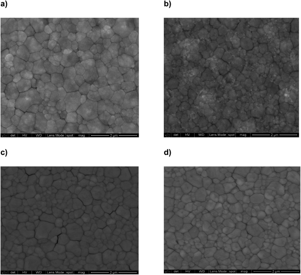 | ||
| Fig. 8 SEM micrographs; (a) MAPbI3; (b) MA0.995(THPhyl)0.005PbI3; (c) MA0.995(ThPhy-Cl)0.005PbI3; (d) MA0.995(ThPhy-BF4)0.005PbI3. | ||
On the other hand, EDS analyzes of the thin films were carried out with the purpose of identifying the incorporation of the elements present in the anions, particularly the chlorine and fluorine anions (Fig. S9†). EDS analysis confirms the presence of both Cl−1 and F−1 ions in a percentage ratio of 5.9% and 6.5% respectively (Tables S2a and b†).
3.5 Optical characterization of MAPbI3 and theophylline derivatives
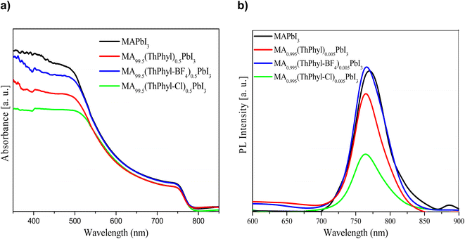
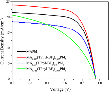
Fig. 9a and b show the representative absorption and emission spectra of MAPbI3 and Theophylline derivatives, respectively. It is well known that MAPbI3 is an excellent photo absorber material, and here it shows a slightly higher absorption than the films with theophylline derivatives. However, the presence of intrinsic defects in thin films and rapid degradation significantly minimize its application in photovoltaic devices when used in its pristine form. Among the theophylline derivatives, THPhyl-FB4 showed higher absorption, and this is attributed to the quality of the film formed by this compound. As previously described in the literature, the BF4− ion has the ability to interact on the perovskite surface removing labile lead atoms. The removal of these lead adatoms and NPs, which act as traps for charge carriers results in an enhancement of the PL of the system, observed in the spectrum. The above can be confirmed by EDS study showing a high percentage of surface lead related to the presence of the THPhyl-FB4.65 The bandgap change described in the theoretical calculations (PDOS Fig. 5) could explain the lower absorption of the films containing the chlorinated additive.In our case, the highest intensity of photoluminescence (PL) was observed when the BF4− was incorporated. Particularly, thin film MA0.995(ThPhy-BF4)0.005PbI3 presented high intensity, which suggests the passivation of the trap states on the surface that prevents the recombination of charges. These same results were obtained by Jen et al.,52 when using NH4BF4 as an additive into a mixed-ion (FAPbI3)0.83(MAPbBr3)0.17 perovskite. BF4− improved photoluminescence lifetime, high recombination resistance, and PCE of 20.16% when 1% NH4BF4 was incorporated. In this study the device with the highest efficiency was when ThPhy-BF4 was incorporated at 0.005% (Fig. 10).
3.6 Photovoltaics solar cells
Finally, the effect of the incorporation of theophylline derivatives was evaluated in photovoltaic devices to observe their electrical properties. Fig. 10 shows the J–V curves. The PCE of pristine MAPbI3 was 13.6%, with an open-circuit voltage (VOC) of 954 mV, a short circuit current density (JSC) of 21.6 mA cm−2, and a fill factor (FF) of 66.2%. The cell that presented the best efficiency was the one manufactured with MA0.995(ThPhyl-BF4)0.005PbI3, with a photovoltaic efficiency of 15.04%, a (VOC) of 954.1 mV, (JSC) of 23.99 mA cm−2, and (FF) of 65.7%. However, when increasing the percentage of ThPhyl-BF4 by 1 and 1.5% in the MAPbI3 solution, the effect was not so significant, the efficiencies were 11 and 9% respectively, this is because increasing the concentration of the additive at the perovskite periphery affects the effective charge transfer.It is possible to observe that the use of MA0.995(ThPhy-Cl)0.005PbI3 in the solar cell generates an efficiency comparable to MA0.995(ThPhy)0.005PbI3, around 13%, and slightly lower than the efficiency obtained with pristine MAPbI3, while in the case of MA0.995(ThPhyl-BF4)0.005PbI3, the obtained efficiency is 15.04 (15% higher). The better charge transfer can explain this favorable result charge transfer from perovskite to the BF4− anion which was described extensively in the theoretical calculations. In the case of the three additives, as the percentage increases the device performance decreases inversely proportional to the protection against humidity shown in the film stability studies. Table 1 summarizes the photovoltaic parameters of fabricated devices.
4 Conclusions
In conclusion, two theophylline derivatives were obtained through their quaternization with hydrochloric and tetrafluoroboric acids. They were employed as additives in perovskite films generating stability at controlled humidity of 30%, especially when the percentage added was 1.5%. The PCE of the champion PSC with MA0.995(ThPhyl-BF4)0.005PbI3 increases significantly to 15.04%, with (VOC), (JSC) and FF of 0.954 mV, 3.6 mA cm−2 and 68.4%, respectively. This result in photovoltaic devices is attributed to the improvement in the morphological properties of the films promoted by theophylline, coupled with higher charge mobility through the BF4− anion, higher light absorption, and added to its intrinsic hydrophobicity. Our work provides a theoretical and experimental approach to improve the efficiency of perovskite solar cells and employed as additives.Author contributions
Investigation was conducted by Rosa Angeles Vazquez-García, Alejandro Valdez- Calderón and Miguel A. Amado-Briseño; Edgar González-Juárez, methodology, validation and writing-original draft; Arian Espinosa-Roa and Eduardo M. Sanchez were responsible for conceptualization, supervision, funding acquisition and project administration; Arian Espinosa-Roa and Jayaramakrishnan Velusamy was responsible for writing-review & editing. Alejandra T. Cadillo-Martínez and Andres M. Garay-Tapia were responsible for the theoretical studies (software) and data curation. All authors agree with the final version.Conflicts of interest
There are no conflicts to declare.Acknowledgements
This study was supported by CONACYT-Fondo Sectorial de Investigación para la Educación 2017–2018/A1-S-13267 and SENER-CONACyT under research project 256766. J. V. is funded by the European Union’s Horizon 2020 research and innovation programme under the Marie Sklodowska-Curie grant agreement no. 101025385References
- A. Kojima, K. Teshima, Y. Shirai and T. Miyasaka, Organometal halide perovskites as visible-light sensitizers for photovoltaic cells, J. Am. Chem. Soc., 2009, 131(17), 6050–6051, DOI:10.1021/ja809598r.
- Alliance for Sustainable Energy LLC, The National Renewable Energy Laboratory is a national laboratory of the U.S. Department of Energy, Office of Energy Efficiency and Renewable Energy, “NREL Transforming Energy”, National Renewable Energy Laboratory, https://www.nrel.gov/pv/cell-efficiency.html Search PubMed.
- P. Roy, N. Kumar Sinha, S. Tiwari and A. Khare, A review on perovskite solar cells: Evolution of architecture, fabrication techniques, commercialization issues and status, Sol. Energy, 2020, 198, 665–688, DOI:10.1016/j.solener.2020.01.080.
- F. Zhang and K. Zhu, Additive Engineering for Efficient and Stable Perovskite Solar Cells, Adv. Energy Mater., 2020, 10(13), 1–26, DOI:10.1002/aenm.201902579.
- W. J. Yin, T. Shi and Y. Yan, Unusual defect physics in CH3NH3PbI3 perovskite solar cell absorber, Appl. Phys. Lett., 2014, 104(6) DOI:10.1063/1.4864778.
- S. Fu, et al., Efficient Passivation with Lead Pyridine-2-Carboxylic for High-Performance and Stable Perovskite Solar Cells, Adv. Energy Mater., 2019, 9(35), 1–10, DOI:10.1002/aenm.201901852.
- X. Zheng, et al., Defect passivation in hybrid perovskite solar cells using quaternary ammonium halide anions and cations, Nat. Energy, 2017, 2(7), 1–9, DOI:10.1038/nenergy.2017.102.
- C. Zhou, et al., Low dimensional metal halide perovskites and hybrids, Mater. Sci. Eng., R, 2019, 137, 38–65, DOI:10.1016/j.mser.2018.12.001.
- C. Ran, J. Xu, W. Gao, C. Huang and S. Dou, Defects in metal triiodide perovskite materials towards high-performance solar cells: origin, impact, characterization, and engineering, Chem. Soc. Rev., 2018, 47(12), 4581–4610, 10.1039/c7cs00868f.
- D. H. Kang and N. G. Park, On the Current–Voltage Hysteresis in Perovskite Solar Cells: Dependence on Perovskite Composition and Methods to Remove Hysteresis, Adv. Mater., 2019, 31(34), 1–23, DOI:10.1002/adma.201805214.
- J. Kim, S. H. Lee, J. H. Lee and K. H. Hong, The role of intrinsic defects in methylammonium lead iodide perovskite, J. Phys. Chem. Lett., 2014, 5(8), 1312–1317, DOI:10.1021/jz500370k.
- H. Uratani and K. Yamashita, Charge Carrier Trapping at Surface Defects of Perovskite Solar Cell Absorbers: A First-Principles Study, J. Phys. Chem. Lett., 2017, 8(4), 742–746, DOI:10.1021/acs.jpclett.7b00055.
- Z. Zhang, L. Qiao, C. Mora-Perez, R. Long and O. V. Prezhdo, Pb dimerization greatly accelerates charge losses in MAPbI3: time-domain ab initio analysis, J. Chem. Phys., 2020, 152(6) DOI:10.1063/1.5131342.
- J. W. Lee, S. G. Kim, J. M. Yang, Y. Yang and N. G. Park, Verification and mitigation of ion migration in perovskite solar cells, APL Mater., 2019, 7(4) DOI:10.1063/1.5085643.
- M. A. Najeeb, et al., Growth of MAPbBr3 perovskite crystals and its interfacial properties with Al and Ag contacts for perovskite solar cells, Opt. Mater., 2017, 73, 50–55, DOI:10.1016/j.optmat.2017.07.043.
- S. Kundu and T. L. Kelly, In situ studies of the degradation mechanisms of perovskite solar cells, EcoMat, 2020, 2(2), 1–22, DOI:10.1002/eom2.12025.
- F. Tian, W. Feng, B. Xing, X. He, W. A. Saidi and L. Zhang, Grain Boundaries in Methylammonium Lead Halide Perovskites Facilitate Water Diffusion, Adv. Energy Sustainability Res., 2021, 2(11), 2100087, DOI:10.1002/aesr.202100087.
- A. Liang, et al., Highly Efficient Halide Perovskite Light-Emitting Diodes via Molecular Passivation, Angew. Chem., Int. Ed., 2021, 60(15), 8337–8343, DOI:10.1002/anie.202100243.
- G. Liu, et al., Interface passivation treatment by halogenated low-dimensional perovskites for high-performance and stable perovskite photovoltaics, Nano Energy, 2020, 73, 104753, DOI:10.1016/j.nanoen.2020.104753.
- M. G. La-Placa, G. Longo, A. Babaei, L. Martínez-Sarti, M. Sessolo and H. J. Bolink, Photoluminescence quantum yield exceeding 80% in low dimensional perovskite thin-films: via passivation control, Chem. Commun., 2017, 53(62), 8707–8710, 10.1039/c7cc04149g.
- W. Li, J. Zhan, X. Liu, J. Tang, W. J. Yin and O. V. Prezhdo, Atomistic Mechanism of Passivation of Halide Vacancies in Lead Halide Perovskites by Alkali Ions, Chem. Mater., 2021, 33(4), 1285–1292, DOI:10.1021/acs.chemmater.0c04188.
- L. Qiao, W. H. Fang, R. Long and O. V. Prezhdo, Atomic Model for Alkali Metal Passivation of Point Defects at Perovskite Grain Boundaries, ACS Energy Lett., 2020, 5(12), 3813–3820, DOI:10.1021/acsenergylett.0c02136.
- J. Peng, et al., Nanoscale localized contacts for high fill factors in polymer-passivated perovskite solar cells, Science, 2021, 371(6527), 390–395, DOI:10.1126/science.abb8687.
- M. Malekshahi Byranvand, et al., Chemical vapor deposited polymer layer for efficient passivation of planar perovskite solar cells, J. Mater. Chem. A, 2020, 8(38), 20122–20132, 10.1039/d0ta06646j.
- X. Hu, H. Wang, M. Wang and Z. Zang, Interfacial defects passivation using fullerene-polymer mixing layer for planar-structure perovskite solar cells with negligible hysteresis, Sol. Energy, 2020, 206, 816–825, DOI:10.1016/j.solener.2020.06.057.
- X. Li, et al., Defects Passivation With Dithienobenzodithiophene-based π-conjugated Polymer for Enhanced Performance of Perovskite Solar Cells, Sol. RRL, 2019, 3(6) DOI:10.1002/solr.201900029.
- Q. Xiao, et al., Dopant-Free Squaraine-Based Polymeric Hole-Transporting Materials with Comprehensive Passivation Effects for Efficient All-Inorganic Perovskite Solar Cells, Angew. Chem., 2019, 131(49), 17888–17894, DOI:10.1002/ange.201907331.
- D. Yoo, et al., Origin of the Stability and Transition from Anionic to Cationic Surface Ligand Passivation of All-Inorganic Cesium Lead Halide Perovskite Nanocrystals, J. Phys. Chem. Lett., 2020, 11(3), 652–658, DOI:10.1021/acs.jpclett.9b03600.
- M. Kazes, T. Udayabhaskararao, S. Dey and D. Oron, Effect of Surface Ligands in Perovskite Nanocrystals: Extending in and Reaching out, Acc. Chem. Res., 2021 DOI:10.1021/acs.accounts.0c00712.
- J. Y. Woo, et al., Highly Stable Cesium Lead Halide Perovskite Nanocrystals through In Situ Lead Halide Inorganic Passivation, Chem. Mater., 2017, 29(17), 7088–7092, DOI:10.1021/acs.chemmater.7b02669.
- H. Zhang, M. K. Nazeeruddin and W. C. H. Choy, Perovskite Photovoltaics: The Significant Role of Ligands in Film Formation, Passivation, and Stability, Adv. Mater., 2019, 31(8), 1–29, DOI:10.1002/adma.201805702.
- E. Aydin, M. De Bastiani and S. De Wolf, Defect and Contact Passivation for Perovskite Solar Cells, Adv. Mater., 2019, 31(25), 1–20, DOI:10.1002/adma.201900428.
- M. S. Lee, et al., Efficient defect passivation of perovskite solar cells: via stitching of an organic bidentate molecule, Sustainable Energy Fuels, 2020, 4(7), 3318–3325, 10.1039/c9se01041f.
- H. Choi, X. Liu, H. Il Kim, D. Kim, T. Park and S. Song, A Facile Surface Passivation Enables Thermally Stable and Efficient Planar Perovskite Solar Cells Using a Novel IDTT-Based Small Molecule Additive, Adv. Energy Mater., 2021 DOI:10.1002/aenm.202003829.
- X. Wu, et al., Efficient perovskite solar cellsviasurface passivation by a multifunctional small organic ionic compound, J. Mater. Chem. A, 2020, 8(17), 8313–8322, 10.1039/d0ta02222e.
- X. Jiang, et al., Direct Surface Passivation of Perovskite Film by 4-Fluorophenethylammonium Iodide toward Stable and Efficient Perovskite Solar Cells, ACS Appl. Mater. Interfaces, 2021, 13(2), 2558–2565, DOI:10.1021/acsami.0c17773.
- K. H. Girish, Advances in surface passivation of perovskites using organic halide salts for efficient and stable solar cells, Surf. Interfaces, 2021, 26, 101420, DOI:10.1016/j.surfin.2021.101420.
- Q. Jiang, et al., Surface passivation of perovskite film for efficient solar cells, Nat. Photonics, 2019, 13(7), 460–466, DOI:10.1038/s41566-019-0398-2.
- Q. He, et al., Surface passivation of perovskite thin films by phosphonium halides for efficient and stable solar cells, J. Mater. Chem. A, 2020, 8(4), 2039–2046, 10.1039/c9ta12597c.
- A. A. Said, J. Xie and Q. Zhang, Recent Progress in Organic Electron Transport Materials in Inverted Perovskite Solar Cells, Small, 2019, 15(27), 1–23, DOI:10.1002/smll.201900854.
- S. Akhil, V. G. V. Dutt, R. Singh and N. Mishra, Surface-State-Mediated Interfacial Hole Transfer Dynamics between CsPbBr3Perovskite Nanocrystals and Phenothiazine Redox Couple, J. Phys. Chem. C, 2021, 125(40), 22133–22141, DOI:10.1021/acs.jpcc.1c07129.
- L. J. Xu, et al., Highly Emissive and Stable Organic–Perovskite Nanocomposite Thin Films with Phosphonium Passivation, J. Phys. Chem. Lett., 2019, 10(19), 5923–5928, DOI:10.1021/acs.jpclett.9b02387.
- M. Mangrulkar and K. J. Stevenson, The progress of additive engineering for CH3NH3PbI3 photo-active layer in the context of perovskite solar cells, Crystals, 2021, 11(7) DOI:10.3390/cryst11070814.
- C. Pereyra, H. Xie and M. Lira-Cantu, Additive engineering for stable halide perovskite solar cells, J. Energy Chem., 2021, 60, 599–634, DOI:10.1016/j.jechem.2021.01.037.
- R. Wang, et al., Caffeine Improves the Performance and Thermal Stability of Perovskite Solar Cells, Joule, 2019, 3(6), 1464–1477, DOI:10.1016/j.joule.2019.04.005.
- R. Wang, et al., Constructive molecular configurations for surface-defect passivation of perovskite photovoltaics, Science, 2019, 366(6472), 1509–1513, DOI:10.1126/science.aay9698.
- Z. Zhang, et al., Organic compound passivation for perovskite solar cells with improving stability and photoelectric performance, Sol. Energy, 2022, 231, 414–419, DOI:10.1016/j.solener.2021.11.075.
- S. Nagane, U. Bansode, O. Game, S. Chhatre and S. Ogale, CH3NH3PbI(3−x)(BF4)x: Molecular ion substituted hybrid perovskite, Chem. Commun., 2014, 50(68), 9741–9744, 10.1039/c4cc04537h.
- S. Nagane and S. Ogale, CH3NH3Pb(BF4)3 and (C4H9NH3)2Pb(BF4)4 Family of 3D and 2D Perovskites without and with Iodide and Bromide Ions Substitution, J. Phys. Chem. Lett., 2016, 7(22), 4757–4762, DOI:10.1021/acs.jpclett.6b02121.
- Y. Sheng, et al., Mixed (5-AVA)xMA1−xPbI3−y(BF4)y perovskites enhance the photovoltaic performance of hole-conductor-free printable mesoscopic solar cells, J. Mater. Chem. A, 2018, 6(5), 2360–2364, 10.1039/c7ta09604f.
- L. Yang, et al., Large-scale synthesis of CH3NH3BF4 crystal and its application on CH3NH3PbBrx(BF4)(3−x) perovskite thin films, Chem. Phys. Lett., 2020, 754 DOI:10.1016/j.cplett.2020.137638.
- J. Zhang, S. Wu, T. Liu, Z. Zhu and A. K. Y. Jen, Boosting Photovoltaic Performance for Lead Halide Perovskites Solar Cells with BF4− Anion Substitutions, Adv. Funct. Mater., 2019, 29(47), 1–8, DOI:10.1002/adfm.201808833.
- S. Bai, et al., Planar perovskite solar cells with long-term stability using ionic liquid additives, Nature, 2019, 571(7764), 245–250, DOI:10.1038/s41586-019-1357-2.
- Y. H. Lin, et al., A piperidinium salt stabilizes efficient metal-halide perovskite solar cells, Science, 2020, 369(6499), 96–102, DOI:10.1126/science.aba1628.
- A. A. Sutanto, et al., Solvent-assisted crystallization via a delayed-annealing approach for highly efficient hybrid mesoscopic/planar perovskite solar cells, Sol. Energy Mater. Sol. Cells, 2017, 172, 270–276, DOI:10.1016/j.solmat.2017.07.043.
- P. E. Blöchl, Projector augmented-wave method, Phys. Rev. B: Condens. Matter Mater. Phys., 1994, 50(24), 17953–17979, DOI:10.1103/PhysRevB.50.17953.
- S. Ehrlich, J. Moellmann, W. Reckien, T. Bredow and S. Grimme, System-dependent dispersion coefficients for the DFT-D3 treatment of adsorption processes on ionic surfaces, ChemPhysChem, 2011, 12(17), 3414–3420, DOI:10.1002/cphc.201100521.
- K. Momma and F. Izumi, VESTA 3 for three-dimensional visualization of crystal, volumetric and morphology data, J. Appl. Crystallogr., 2011, 44(6), 1272–1276, DOI:10.1107/S0021889811038970.
- A. R. Buist, A. R. Kennedy and C. Manzie, Four salt phases of theophylline, Acta Crystallogr., Sect. C: Struct. Chem., 2014, 70(2), 220–224, DOI:10.1107/S2053229614000825.
- Z. Wu, M. Jiang, Z. Liu, A. Jamshaid, L. K. Ono and Y. Qi, Highly Efficient Perovskite Solar Cells Enabled by Multiple Ligand Passivation, Adv. Energy Mater., 2020, 10(10) DOI:10.1002/aenm.201903696.
- H. Qin, L. Xu and D. Zhong, First-Principles Study of Zinc Phthalocyanine Molecules Adsorbed on Methylammonium Lead Iodide Surfaces, J. Phys. Chem. C, 2020, 124(9), 5167–5173, DOI:10.1021/acs.jpcc.9b10664.
- X. Hu, H. Wang, M. Wang and Z. Zang, Interfacial defects passivation using fullerene-polymer mixing layer for planar-structure perovskite solar cells with negligible hysteresis, Sol. Energy, 2020, 206, 816–825, DOI:10.1016/j.solener.2020.06.057.
- E. Gonzalez-Juarez, K. Valadez-Villalobos, D. F. Garcia-Gutierrez, D. I. Garcia-Gutierrez, A. E. Roa and E. Sanchez, Study on photovoltaic stability and performance by incorporating tetrabutyl phosphonium iodide into the active layer of a perovskite type photovoltaic cell, RSC Adv., 2020, 10(52), 31575–31585, 10.1039/d0ra04630b.
- M. Salado, et al., Extending the Lifetime of Perovskite Solar Cells using a Perfluorinated Dopant, ChemSusChem, 2016, 9(18), 2708–2714, DOI:10.1002/cssc.201601030.
- T. Ahmed, S. Seth and A. Samanta, Boosting the Photoluminescence of CsPbX3 (X = Cl, Br, I) Perovskite Nanocrystals Covering a Wide Wavelength Range by PostsyntheticTreatment with Tetrafluoroborate Salt, Chem. Mater., 2018, 30, 3633–3637, DOI:10.1021/acs.chemmater.8b01235.
Footnotes |
| † Electronic supplementary information (ESI) available. See DOI: https://doi.org/10.1039/d2ra07580f |
| ‡ These authors contributed equally to this work. |
| This journal is © The Royal Society of Chemistry 2023 |

