 Open Access Article
Growth of polyoxomolybdate with a porous pyramidal structure on carbon xerogel nanodiamond as an efficient electro-catalyst for oxygen reduction reaction†
Abeer Enaiet Allah a,
Mohamed M. EL-Deebb,
Ahmed A. Farghalic,
H. El Molld and
Abdalla Abdelwahab
 *ce
*ce
aChemistry Department, Faculty of Science, Beni-Suef University, Beni-Suef 62511, Egypt
bApplied Electrochemistry Laboratory, Chemistry Department, Faculty of Science, Beni-Suef University, 62511 Beni-Suef, Egypt
cMaterials Science and Nanotechnology Department, Faculty of Postgraduate Studies for Advanced Sciences, Beni-Suef University, Beni-Suef 62511, Egypt. E-mail: aabdelwahab@psas.bsu.edu.eg
dDepartment of Chemistry, College of Science, University of Hail, P.O. Box 2440, 81451 Hail, Kingdom of Saudi Arabia
eFaculty of Science, Galala University, Sokhna, Suez 43511, Egypt
First published on 13th March 2023
Abstract
The slow kinetics of the oxygen reduction reaction (ORR) limits the large-scale usage of the fuel cells. Thus, it is crucial to develop an efficient and stable electrocatalyst for the ORR. Herein, facile synthesis of three-dimensional nitrogen-doped carbon xerogel diamond nanoparticles, CDNPs support is reported. The as-prepared CDNPs support was functionalized with a Keggin-type polyoxomolybdate via the hydrothermal process (POM@CDNPs). As the characterization techniques revealed, this nanocomposite possesses a three-dimensional structure, high density of nitrogen doping, and well-dispersed porous pyramidal morphology of POM, making it a promising catalyst for ORR in alkaline medium. The POM@CDNPs nanocomposite exhibits an outstanding activity for ORR with a limiting current density that reaches −7.30 mA cm−2 at 0.17 V vs. RHE. Moreover, a half-wave potential of 0.773 V is delivered with a stability of about 99.9% after the 100th repetitive cycle as this catalyst forces the ORR to the direct-four-electron pathway. This work spots the advantages of hybridizing the sp3 of the nanodiamond with the sp2 of the carbon xerogels to increase the conductivity of the support material. In addition, the role of the porous pyramidal morphology of the POM on the activity of the nanocomposite was evaluated. This study suggests using advanced carbon-based electro-catalysts with outstanding activity and stability.
1. Introduction
Due to the recent challenges of climate change and the continuous increase of environmental pollution, finding and developing clean and renewable energies is of vital importance in the coming years.1,2 Thus, the development of novel renewable energy conversion and storage systems such as metal-air batteries, hydrogen production, and fuel cells, has been extensively studied from the laboratory scale to the industrial point of view.3 Among the renewable energy systems, fuel cells are considered promising power sources as they are capable of converting chemical energy directly into electricity with high efficiencies without any polluting emissions. In the fuel cells, two reactions are carried out at the anode and cathode. At the anode, a fuel such as hydrogen or methanol is oxidized, while at the cathode an oxygen reduction reaction (ORR) occurs. Unfortunately, the reaction kinetics of oxygen reduction is very slow, implying that high reduction potentials are required which in turn decreases the fuel cell's performance and limits their market use. Therefore, the use of an efficient electro-catalyst (EC) is crucial and of great importance for developing the ORR kinetics and the overall fuel cell performance.Platinum, Pt, and its alloys are considered the most effective electro-catalysts (ECs) for the ORR which provide low ORR over-potentials, large current densities, and are selective for the direct four-electron pathway.4–6 However, platinum-based electro-catalysts are not considered the best solutions for increasing the ORR kinetics as they suffer from several drawbacks such as scarcity, high cost, and poisoning of Pt by the CO intermediate species which results in poor stability and durability.7
During the past few years, the research is directed to find a platinum-free electro-catalyst with satisfying activity and durability. Carbon nanomaterials have been applied as electro-catalysts for ORR as metal-free ECs in alkaline medium owing to their high surface areas, good electrical properties, and high chemical and thermal stabilities.8–10 Additionally, carbon nanomaterials doped with different transition metal oxides are used as a support material to enhance activity and stability.11–14 Carbon nanomaterials can also be doped with nitrogen, sulfur, or phosphorous, and the results showed that nitrogen-doped carbon has the best performance towards ORR among their alternatives.1,15 The development of ORR activity of carbon upon doping with nitrogen or another dopant is due to the increase of electroactive sites on high surface area and enhanced conductivity.
In ORR application, various carbon-based electrocatalysts were employed such as carbon nanotubes,16 graphene,17 and carbon xerogels. In this context, nitrogen-doped carbon xerogels (C) are novel carbon materials comprising sp2-bonded carbon atoms, high specific surface areas, and an open three-dimensional porous structure. This porous structure allows for enhancing the transport and diffusion of ions, resulting in better ORR performance. Moreover, diamond nanoparticles (DNPs) are new carbon allotropes with a combination of sp2 and sp3 hybridization which possesses excellent electrical properties, high surface areas, and good mechanical properties.
In addition, polyoxometalates (POMs) are among the promising species that can be immobilized on a carbon matrix. They include a large class of inorganic oxides containing oxygen and transition metals with excellent activity in many applications.3,17,18 The advantages of using POMs as an electro-catalyst in ORR are their rich redox chemistry which gives rise to mixed-valence species, structural flexibility, high thermodynamic oxidation stability, and fast and reversible multiple electron redox properties.19 Different carbon materials were used as the ideal support for the dispersion of POMs such as graphene,17 graphitic carbon nitride,18 and carbon black.20 But the use of POMs in ORR is still limited because of their low surface area, lower stability, and degradation in the aqueous media.19,21 Diana M. Fernandes et al. reported the preparation of polyoxotungstate immobilized on different carbon support nanomaterials in an alkaline medium.1 A diffusion-limiting current density of −168.3 mA cm−2 mg−1 was obtained for Co4(PW9)2@N-CNT. Marta Nunes et al. prepared several nanocomposites by the incorporation of vanadium-substituted phosphomolybdate into different carbon supports. They found that the nanocomposite supported on graphene as PMo11V@graphene exhibited the best ORR performance.22
Taking into account that POMs-based nanocomposites have shown high efficiency towards ORR and the nanocomposite containing POMs supported on nitrogen-doped carbon diamond hasn't been used before as an electrocatalyst for ORR. Thus, this work reports the successful preparation and application of polyoxomolybdate supported on nitrogen-doped carbon xerogel/diamond matrix for ORR in an alkaline medium. The porous carbon xerogels were prepared from the resorcinol–formaldehyde monomers through the sol–gel method. Then, the nitrogen-doped carbon xerogel diamond matrix was prepared by simply mixing and annealing the precursors in a tube furnace at 600 °C for 2 h under the N2 atmosphere. Finally, the nanocomposite of polyoxomolybdate supported on nitrogen-doped carbon xerogel/diamond POM@CDNPs was obtained through a hydrothermal process. The purpose of this work is to evaluate the importance of hybridizing the sp3 of nanodiamond with sp2 of carbon xerogels to increase the conductivity of the support material. Moreover, the effect of the morphology of the polyoxomolybdate on the catalytic activity of the nanocomposite to the ORR is evaluated.
2. Experimental section
2.1. Preparation of POM
0.8 g of hydrazinium sulfate (N2H4·H2SO4, 6.1 mmol) was added to a solution containing 5.6 g of ammonium molybdate tetrahydrate ((NH4)6Mo7O24·4H2O, 4.5 mmol) and 12.5 g of ammonium acetate (CH3COONH4, 162.2 mmol) in 250 mL H2O. The solution was stirred for 10 min and when the colour changed to blue-green, 83 mL of acetic acid, CH3COOH (50%) was added. When the solution turns green, it is stored in an open 500 mL Erlenmeyer flask at 20 °C without further stirring. After four days in the fume hood, the precipitated crystals with red-brown colour were filtered, washed with 90% ethanol, and finally dried in the air.2.2. Preparation of porous carbon xerogel (C)
Carbon xerogel was prepared as reported previously.23 Briefly, the resorcinol (R) and formaldehyde (F) were mixed in water (W) with appropriate molar ratios using cobalt acetate as the polymerization catalyst. The amount of cobalt in the final carbon xerogel matrix was calculated to be 1%. The R/F and R/W molar ratios were 1![[thin space (1/6-em)]](https://www.rsc.org/images/entities/char_2009.gif) :
:![[thin space (1/6-em)]](https://www.rsc.org/images/entities/char_2009.gif) 2 and 1
2 and 1![[thin space (1/6-em)]](https://www.rsc.org/images/entities/char_2009.gif) :
:![[thin space (1/6-em)]](https://www.rsc.org/images/entities/char_2009.gif) 17, respectively. Then, the obtained solution was subjected to stirring and casting into glass molds. The curing temperature was 40 °C for 24 h, followed by keeping it at 80 °C for five days. After that, the obtained organic gels were dried using microwave heating to receive their corresponding organic xerogel. Finally, the C was obtained by carbonization of organic xerogel at 900 °C with a heating rate of 5 °C min−1 under N2 gas flow in a tube furnace for 2 h.
17, respectively. Then, the obtained solution was subjected to stirring and casting into glass molds. The curing temperature was 40 °C for 24 h, followed by keeping it at 80 °C for five days. After that, the obtained organic gels were dried using microwave heating to receive their corresponding organic xerogel. Finally, the C was obtained by carbonization of organic xerogel at 900 °C with a heating rate of 5 °C min−1 under N2 gas flow in a tube furnace for 2 h.
2.3. Preparation of nitrogen-doped carbon diamond (CDNPs)
The nitrogen-doped carbon diamond matrix was prepared by simply mixing 10.0 g of urea, 100 mg of carbon xerogel, and 10 mg of nanodiamond. The amount of nanodiamond in the carbon xerogel matrix was calculated to be 10 wt%. Physical mixing using mortar was performed, and then the produced powder was thermally treated in a tube furnace at 600 °C for 2 h under an N2 atmosphere with a heating rate of 10 °C min−1.2.4. Preparation of POM@nitrogen-doped carbon diamond composites (POM@CDNPs)
POM@CDNPs composite electro-catalyst was prepared as follows: 0.09 g of CDNPs was dissolved in 40.0 mL of ethanol solution and sonicated for 10 minutes. The aqueous solution of 0.03 g of POM in 15 mL of water was added to the above suspension under stirring for 1 h. Then, the resulting mixture was diluted with 105 mL of water in a Teflon-lined autoclave (200 mL). After that, the autoclave was placed inside an oven and maintained at 150 °C for 24 h. After the hydrothermal reaction, the resulting precipitate was washed using hot DI water and ethanol several times by centrifuge. Finally, the obtained powder was dried in an oven at 60 °C for 12 h.2.5. Characterization
The characterization of materials' crystallinity was performed using powder X-ray diffraction (XRD, PANalytical Empyrean, Netherlands). Also, the surface morphologies of the prepared materials were investigated using field emission scanning electron microscopy (FESEM, ZEISS, EVOMA10). The materials' microstructure and the POM dispersion were determined with high-resolution transmission electron microscopy (HRTEM, JEM2100, Jeol, Japan). The materials' porosity and their corresponding surface areas were evaluated using Micromeritics surface area analyzer (TriStar II 3020, Micromeritics, USA) to record nitrogen adsorption–desorption isotherms at 77 K. The materials' chemical composition and their oxidation states were tested with X-ray photoelectron spectroscopy (XPS, K-ALPHA, Thermo Fisher Scientific, USA).2.6. Electrochemical measurements and electrode preparation
The working electrode was prepared by dispersing 5 mg of the as-prepared material in 400 μL isopropanol solution and 15 μL Nafion (5 wt%). The suspension was sonicated for 10 minutes then, 10 μL of the resultant ink was drop cast onto a rotating disk electrode (RDE) with a glassy carbon tip of 3 mm in diameter.A three-electrode electrochemical cell was designed using graphite rode and Ag/AgCl as the counter and the reference electrodes, respectively. The used electrolyte was 0.1 M KOH which is saturated with N2 or O2 prior to the electrochemical measurements. The electrochemical tests were carried out using a potentiostat/galvanostat (AUTO LAB PGSTAT 302N, Metrohm, Utrecht, The Netherlands). The cyclic voltammetry (CV) measurements were carried out in a potential window between −0.8 to 0.4 V at a scan rate of 50 mV s−1. The linear sweep voltammetry (LSV) tests were performed in O2 saturated electrolyte at different rotation speeds from 500 to 3000 rpm at a scan rate of 5 mV s−1. The stability test was carried out using LSV at 3000 rpm at a scan rate of 50 mV s−1 for 100th repetitive cycles. For comparisons, the potential of the Ag/AgCl reference electrode was converted to the reversible hydrogen electrode (RHE).
The number of transferred electrons; n, was evaluated using the Koutecky–Levich (K–L) model through the following relations:
| B = 0.2nF(DO2)2/3ν−1/6CO2 |
3. Results and discussions
3.1. Physicochemical characterization
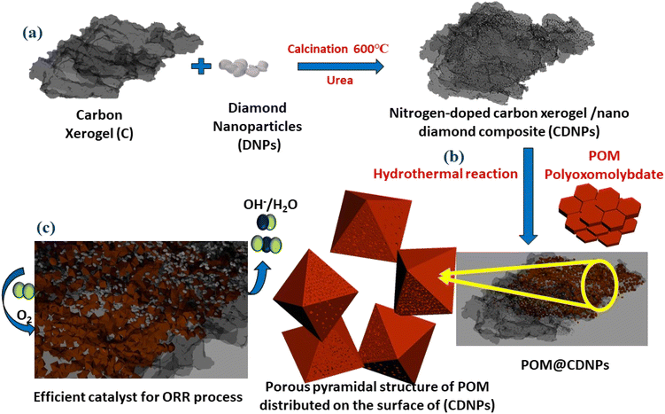
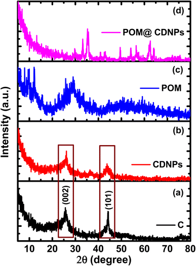
The synthesis process of the POM@CDNPs electro-catalyst is illustrated in Fig. 1. Firstly, the C, DNPs and urea were mixed and calcined at 600 °C to form CDNPs. POM and CDNPs were mixed uniformly in an ethanol solution. Based on the spontaneous bonding of negatively charged POM moieties and positively charged nitrogen dopants at the surface of CDNPs, POM is successfully anchored to the carbon matrix.24 Interestingly, under the hydrothermal reaction, POM hexagonal plates are aggregated in the form of a porous pyramidal structure. Finally, the 3D structure of POM in a pyramidal structure supported on the carbon matrix was obtained.The crystalline structure of the prepared materials was analyzed by XRD, Fig. 2. Fig. 2a and b, shows the XRD pattern for the C and CDNPs matrix in which the two characteristic graphitic peaks are displayed at 2θ of about 26° and 44.25°, which are assigned to the (002) and (101) reflection planes. In addition, Fig. 2c displays the XRD pattern of polyoxomolybdate; POM, in which the characteristic peaks of POM are observed at 2θ of 8.95°, 18.49°, 26.43°, 27.65°, and 28.84° which are corresponding to (0![[1 with combining macron]](https://www.rsc.org/images/entities/char_0031_0304.gif) 1), (
1), (![[2 with combining macron]](https://www.rsc.org/images/entities/char_0032_0304.gif) 02), (
02), (![[1 with combining macron]](https://www.rsc.org/images/entities/char_0031_0304.gif)
![[4 with combining macron]](https://www.rsc.org/images/entities/char_0034_0304.gif) 1), (3
1), (3![[1 with combining macron]](https://www.rsc.org/images/entities/char_0031_0304.gif) 1), and (
1), and (![[3 with combining macron]](https://www.rsc.org/images/entities/char_0033_0304.gif) 12) [JCDPS file no.: 00-043-0317].19,25 Moreover, the broad peak centered at 2θ of 28.84° confirming the layered structure of Keggin-type POM.26 The diffraction pattern of POM@CDNPs composite is shown in Fig. 2d. The existence of several diffraction peaks was attributed to the incorporation of POM polyanion inside the CDNPs matrix. Higher peak intensities are noticed in the case of POM@CDNPs, indicating the increase in the degree of crystallinity and crystallite size. It is noted that the diffraction peaks assigned to POM between 8.95°–26.43° are hardly observed in the POM@CDNPs nanocomposite, possibly due to the excellent dispersion, structure change, and low content of POM molecules in the nanocomposite.27
12) [JCDPS file no.: 00-043-0317].19,25 Moreover, the broad peak centered at 2θ of 28.84° confirming the layered structure of Keggin-type POM.26 The diffraction pattern of POM@CDNPs composite is shown in Fig. 2d. The existence of several diffraction peaks was attributed to the incorporation of POM polyanion inside the CDNPs matrix. Higher peak intensities are noticed in the case of POM@CDNPs, indicating the increase in the degree of crystallinity and crystallite size. It is noted that the diffraction peaks assigned to POM between 8.95°–26.43° are hardly observed in the POM@CDNPs nanocomposite, possibly due to the excellent dispersion, structure change, and low content of POM molecules in the nanocomposite.27
The investigation of the materials' porous structure was carried out using nitrogen adsorption/desorption at 77 K, while the pore size distributions were calculated using the non-local density functional theory (NLDFT), Fig. 3. As shown in Fig. 3a, the N2 adsorption/desorption isotherm for C is typical of type I isotherm with little contribution from the type II isotherm. The C isotherm suggests that the majority of the pores are in the micropore range with few mesopores. In addition, there is a sharp increase in the N2 adsorption at low relative pressure P/P° < 0.1, indicating the micropores filling and the formation of the monolayer. On the other hand, the N2 adsorption isotherms for CDNPs and POM@CDNPs, Fig. 3a, are combinations between type I and type IV isotherms with micro/meso pores contribution. This development in the mesopore character is very important in the catalysis application as it enhances the ionic diffusion inside the materials which in turn promotes the ORR activity. In Fig. 3b, a very low quantity of N2 gas is adsorbed, suggesting a very low surface area and large particle sizes for POM. These findings are also confirmed by the calculations of the pore size distributions using NLDFT calculations, Fig. 3c and d. The development of the mesopore diameter is observed for POM@CDNPs with an average pore size of 3.29 nm. While for C and CDNPs most of the pores are in the micropore range. The data of specific surface area (SBET), micropore volume (V0) and pore diameter (L0) for the prepared materials are compiled in Table 1. Although the C has the highest specific surface area and micropore volume, its pore diameter is not as high as that of POM@CDNPs. The increase in pore diameter means higher adsorption of oxygen molecules.
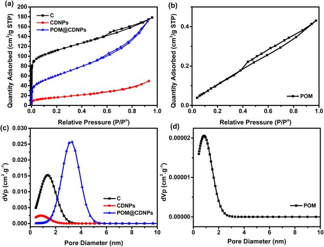 | ||
| Fig. 3 (a) and (b) N2 adsorption/desorption isotherms for the prepared materials and (c) and (d) their corresponding pore diameters. | ||
| Sample | SBET, m2 g−1 | V0 (N2), cm3 g−1 | L0 (NLDFT), nm |
|---|---|---|---|
| C | 408 | 0.276 | 1.29 |
| CDNPs | 59 | 0.076 | 0.73 |
| POM | 5 | 0.006 | 0.73 |
| POM@CDNPs | 222 | 0.264 | 3.29 |
The materials' surface morphologies were investigated using FESEM, Fig. 4. The morphology of three-dimensional (3D) interconnected particles was observed for both C and CDNPs materials, Fig. 4a and b. This 3D network is an important parameter in the catalysis application as it implies high surface accessibility for the electrolytic ions that increases the ions adsorption which in turn enhances the overall catalytic efficiencies. Fig. 4c shows the FESEM image for POM, in which two-dimensional aggregated hexagonal plates were observed. On the other hand, the aggregation of POM clusters on the surface of CDNPs is shown in Fig. 4d and e. As can be seen, pyramidal shapes of Keplerate-type polyoxomolybdate are grown onto the CDNPs surface. These pyramidal shapes are not connected and are homogenously dispersed over the ample CDNPs matrix. Interestingly, a porous structure is noticed for the pyramidal shapes of POM, Fig. S1.†
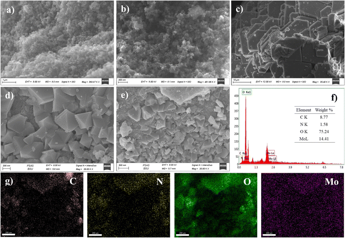 | ||
| Fig. 4 FESEM images for (a) C, (b) CDNPs, (c) POM, (d) and (e) POM@CDNPs, (f) EDX spectrum and (g) EDX elemental mapping for POM@CDNPs. | ||
This porous structure can act as additional active sites for oxygen molecules adsorption in the catalysis application. The EDX spectrum and EDX elemental mapping for POM@CDNPs are shown in Fig. 4f and g, respectively. The EDX spectrum confirms the successful preparation of POM@CDNPs in the absence of any foreign peaks. While in the elemental mapping analysis, a homogenous distribution of the elements throughout the structure was observed.
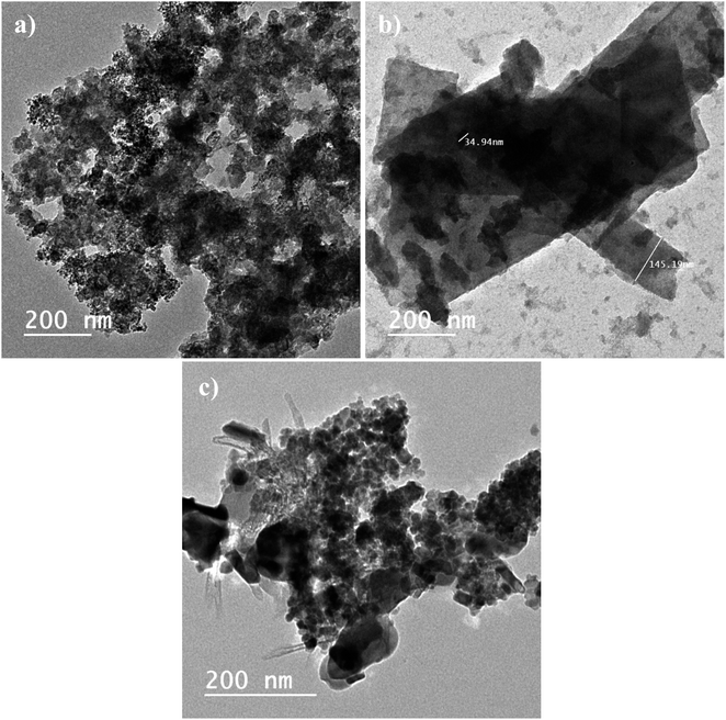
Fig. 5, shows the HRTEM images for CDNPs, POM, and POM@CDNPs. Clearly, there is a good agreement between FESEM and HRTEM images for the prepared materials. For example, in Fig. 5a, a 3D structure for CDNPs is observed with a uniform distribution of the nanodiamond over the carbon structure. The size of the nanodiamond particles is ranging between 4–7 nm in diameter as shown in Fig. S2a.† Moreover, 2D giant layered plates of POM are observed in Fig. 5b. The successful integration of POM molecules over the carbon diamond structure is confirmed in Fig. 5c. A deep investigation of POM@CDNPs is shown in Fig. S2b,† where the POM particles are well distributed over the carbon diamond structure.
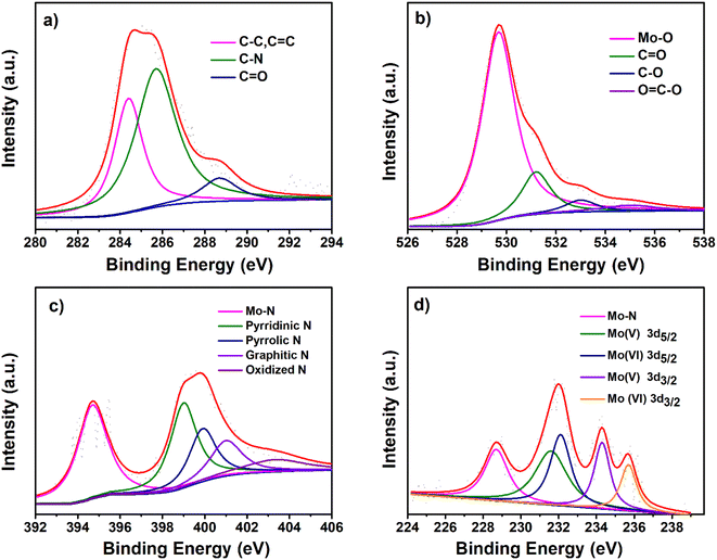
High-resolution X-ray photoelectron spectroscopy (XPS) was carried out to gain further information about the surface chemical composition in the prepared composite POM@CDNPs comprising CDNPs and POM as shown in Fig. 6. The survey XPS spectra demonstrate the existence of the elements of each sample, (C, O, N and Co) in CDNPs, (C, O, N and Mo) in POM, (C, O, N, Co, and Mo) in the nanocomposites POM@CDNPs which confirms its successful preparation, Fig. S3a–c.† Additionally, there was a remarkable oxygen percentage increase after the POM incorporation on the surface of CDNPs, asserting the POM's existence in the composite materials. The contents of different types of nitrogen for CDNPs and POM@CDNPs were shown in Fig. S4a and b.† The XPS spectra of the pristine CDNPs and POM were also performed for comparison with POM@CDNPs, as shown in Fig. S5 and S6,† respectively. The high-resolution C 1s XPS spectrum of CDNPs can be resolved to four peaks, which can be ascribed to C–C, C![[double bond, length as m-dash]](https://www.rsc.org/images/entities/char_e001.gif) C (284.60 eV), C–N (285.3), C–O (286.4 eV), and –COO (288.9 eV) bonding, Fig. S5a.† The fitting of C 1s spectrum of POM was similar to that of pristine CDNPs, the major difference is the absence of C–N bond at 285.3 eV, Fig. S6a.† For POM@CDNPs, Fig. 6 shows a C 1s spectrum with three fitted peaks for graphitic carbon, C–N, and –carboxylic COO at a binding energy of 284.4 eV, 285.7 eV, and 288.7 eV in good harmony with the deconvoluted peak of its counterparts CDNPs and POM.28 As shown in Fig. S5b,† the O 1s XPS spectrum of CDNPs demonstrates four components at 529.1, 530, 531.8, and 533 eV corresponding to chemisorbed oxygen, C
C (284.60 eV), C–N (285.3), C–O (286.4 eV), and –COO (288.9 eV) bonding, Fig. S5a.† The fitting of C 1s spectrum of POM was similar to that of pristine CDNPs, the major difference is the absence of C–N bond at 285.3 eV, Fig. S6a.† For POM@CDNPs, Fig. 6 shows a C 1s spectrum with three fitted peaks for graphitic carbon, C–N, and –carboxylic COO at a binding energy of 284.4 eV, 285.7 eV, and 288.7 eV in good harmony with the deconvoluted peak of its counterparts CDNPs and POM.28 As shown in Fig. S5b,† the O 1s XPS spectrum of CDNPs demonstrates four components at 529.1, 530, 531.8, and 533 eV corresponding to chemisorbed oxygen, C![[double bond, length as m-dash]](https://www.rsc.org/images/entities/char_e001.gif) O (ketone, quinone moieties), C–O from the ether and phenol groups, and carboxylic acids COOH. For the POM sample, Fig. S6b,† the O 1s spectrum exhibits two peaks at binding energies 530 eV and 531.4 eV which are belonging to lattice oxygen bonding in Mo–O and oxygen of the OH– groups of Mo–OH, respectively.20,29 Obviously, the O 1s high-resolution spectrum of POM@CDNPs in Fig. 6b was fitted into four peaks at 529.7, 531.2 533, and 535 eV which can be attributed to Mo–O, O
O (ketone, quinone moieties), C–O from the ether and phenol groups, and carboxylic acids COOH. For the POM sample, Fig. S6b,† the O 1s spectrum exhibits two peaks at binding energies 530 eV and 531.4 eV which are belonging to lattice oxygen bonding in Mo–O and oxygen of the OH– groups of Mo–OH, respectively.20,29 Obviously, the O 1s high-resolution spectrum of POM@CDNPs in Fig. 6b was fitted into four peaks at 529.7, 531.2 533, and 535 eV which can be attributed to Mo–O, O![[double bond, length as m-dash]](https://www.rsc.org/images/entities/char_e001.gif) C, O–C and, COO–, respectively.3 Notably, the O 1s peak for Mo–O in POM@CDNPs shifts to lower binding energy by 0.3 eV relative to that for bare POM, indicating the formation of a covalent C–O–Mo4+ bond on POM@CDNPs.30 The high-resolution N 1s spectrum for the bare CDNPs catalyst, Fig. S5c,† presents four peaks corresponding to pyridinic N (27.11 at%) at 398.2 eV, pyrrolic N (33.89 at%) at 399.7 eV, graphitic N (30.50 at%) at (400.5 eV), and oxidized N (8.47.0 at%) at 403.3 eV (Fig. S5c†). For POM the N 1s spectrum shows peaks at binding energies of 398.6, and 401.7 eV, which are attributed to the imine bond (sp2 hybridized nitrogen C
C, O–C and, COO–, respectively.3 Notably, the O 1s peak for Mo–O in POM@CDNPs shifts to lower binding energy by 0.3 eV relative to that for bare POM, indicating the formation of a covalent C–O–Mo4+ bond on POM@CDNPs.30 The high-resolution N 1s spectrum for the bare CDNPs catalyst, Fig. S5c,† presents four peaks corresponding to pyridinic N (27.11 at%) at 398.2 eV, pyrrolic N (33.89 at%) at 399.7 eV, graphitic N (30.50 at%) at (400.5 eV), and oxidized N (8.47.0 at%) at 403.3 eV (Fig. S5c†). For POM the N 1s spectrum shows peaks at binding energies of 398.6, and 401.7 eV, which are attributed to the imine bond (sp2 hybridized nitrogen C![[double bond, length as m-dash]](https://www.rsc.org/images/entities/char_e001.gif) N–C) involved in triazine rings, and positively charged nitrogen as a quaternary amino group (–NR3)+ in ammonium group, Fig. S6c.† For the comparison of POM@CDNPs with CDNPs in Fig. 6c, pyridinic-N (29.96 at%), pyrrolic-N (16.85 at%), graphitic-N (13.48%), and oxidized N (8.98%) still exist, with the shift to high binding energy as the corresponding peaks appears at 398.9, 399.9, 401and 403.3 eV, respectively. Additionally, an obvious peak of Mo–N (33.70%) at a binding energy of 394.8 eV can be detected due to the strong binding of Mo with N.3 In general, Mo–N and pyridinic N are regarded as electroactive sites, which would elevate the current density and enhance the electrocatalytic activity.31–33 Fig. S6d,† manifest the deconvoluted Mo 3d spectrum into two spin–orbit doublets in POM. The peaks at 231.9 eV and 234.7 eV are assigned to 3d5/2 and 3d3/2 of the Mo (+V) state. In addition, the two peaks located at 232.9 eV and 235.9 eV correspond to 3d5/2 and 3d3/2 of Mo (+VI) state.19 In the case of POM@CDNPs the Mo 3d spectrum, Fig. 6d, was deconvoluted into five peaks which are ascribed to Mo–N (228.6 eV), the peak at 231.5 eV and 234.3 eV corresponding 3d5/2 and 3d3/2 of Mo (+V) state. In addition, the two peaks located at 232.5 eV and 235.5 eV correspond to 3d5/2 and 3d3/2 of the Mo (+VI) state. Remarkably, all XPS signals of O 1s, and Mo 3d for POM@CDNPs shift to the lower binding energy than bare NCD and POM, while the C 1s and N 1s maintain the shift to the higher binding energy. This suggests a strong interaction at the interface between CDNPs and POM due to the formation of the C–Mo bond, which facilitates the interfacial charge transfer in the POM@CDNPs nanocomposite.30
N–C) involved in triazine rings, and positively charged nitrogen as a quaternary amino group (–NR3)+ in ammonium group, Fig. S6c.† For the comparison of POM@CDNPs with CDNPs in Fig. 6c, pyridinic-N (29.96 at%), pyrrolic-N (16.85 at%), graphitic-N (13.48%), and oxidized N (8.98%) still exist, with the shift to high binding energy as the corresponding peaks appears at 398.9, 399.9, 401and 403.3 eV, respectively. Additionally, an obvious peak of Mo–N (33.70%) at a binding energy of 394.8 eV can be detected due to the strong binding of Mo with N.3 In general, Mo–N and pyridinic N are regarded as electroactive sites, which would elevate the current density and enhance the electrocatalytic activity.31–33 Fig. S6d,† manifest the deconvoluted Mo 3d spectrum into two spin–orbit doublets in POM. The peaks at 231.9 eV and 234.7 eV are assigned to 3d5/2 and 3d3/2 of the Mo (+V) state. In addition, the two peaks located at 232.9 eV and 235.9 eV correspond to 3d5/2 and 3d3/2 of Mo (+VI) state.19 In the case of POM@CDNPs the Mo 3d spectrum, Fig. 6d, was deconvoluted into five peaks which are ascribed to Mo–N (228.6 eV), the peak at 231.5 eV and 234.3 eV corresponding 3d5/2 and 3d3/2 of Mo (+V) state. In addition, the two peaks located at 232.5 eV and 235.5 eV correspond to 3d5/2 and 3d3/2 of the Mo (+VI) state. Remarkably, all XPS signals of O 1s, and Mo 3d for POM@CDNPs shift to the lower binding energy than bare NCD and POM, while the C 1s and N 1s maintain the shift to the higher binding energy. This suggests a strong interaction at the interface between CDNPs and POM due to the formation of the C–Mo bond, which facilitates the interfacial charge transfer in the POM@CDNPs nanocomposite.30
3.2. The electrochemical ORR performance
To evaluate the electrochemical performance of the prepared samples toward the ORR, cyclic voltammetry (CV) was performed using an RDE at 50 mV s−1 in oxygen and nitrogen saturated 0.1 M KOH electrolyte, respectively (Fig. 7). Next, linear sweep voltammetry (LSV) measurements at a different speed in O2-saturated 0.1 M KOH electrolyte were recorded for CDNPs and POM@CDNPs samples as shown in Fig. 7.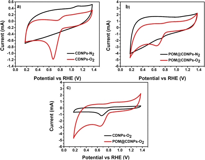 | ||
| Fig. 7 CVs of (a) CDNPs and (b) POM@CDNPs in both N2- and O2-saturated electrolytes and (c) a comparison for both samples in O2-saturated electrolyte recorded at a scan rate of 50 mV s−1. | ||
Fig. 7a and b shows the comparative CV for CDNPs and POM@CDNPs in N2 and O2 saturated electrolytes at a scan rate of 50 mV s−1. As seen in the figure, the obtained voltammograms do not show any sign of redox behaviour where no reduction peak for O2 in presence of N2 saturated electrolyte as it shows only capacitive behaviour. In addition, upon saturation of electrolyte with oxygen gas, the CDNPs shows a distinct reduction peak at around 0.68 V. Remarkably the intensity of this peak is increased and the reduction potential was shifted to 0.72 V in the case of POM@CDNPs due to electro-reduction of oxygen which revealing the high electrochemical activity of POM@CDNPs toward the ORR. As shown in Fig. 7c, the POM@CDNPs exhibit outstanding activity and high performance toward the ORR which can be attributed to four factors, (i) high distribution and anchoring of molybdenum-oxo clusters as stable, adequate, and reactive sites on high surface-area and porous carbon substrate that confer fast mass and electron transport.34,35 (ii) The chemical structure of the DNPs that contains the core of sp3 bonded crystalline diamond and the outer structure of a combined bonding of sp2 and sp3. This distinctive structure of the DNPs is responsible for boosting the redox reactions. (iii) The N doping of C enhances the electrical conductivity and fosters charge transfer. (iv) The presence of abundant graphitic-N and pyridinic-N as dopants for the C matrix endow its surface with positively charged (C+) active sites that reinforce the oxygen adsorption on its surface.
To gain insight into intrinsic electro-catalytic activity activities of samples toward oxygen reduction reaction (ORR), the linear sweep voltammetry (LSV) measurements were acquired using RDE at a rotation speed in the range of 500–3000 rpm at a scan rate of 5 mV s−1.
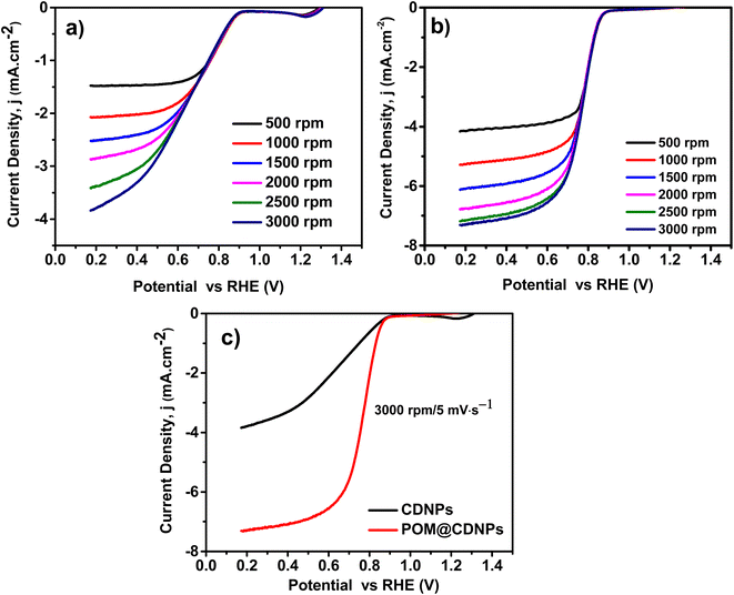
Fig. 8 displays the LSV plots of the electro-catalysts recorded at a rotation speed of from 500 to 3000 rpm and a scan rate of 5 mV s−1. Noticeably POM@CDNPs revealed a low ORR onset potential (Eonset) at 0.890 V vs. RHE, which is more positive relative to that of the CDNPs catalysts 0.873 vs. RHE. From Fig. 8a and b, the obtained current density values for CDNPs and POM@CDNPs are −3.89 mA cm−2 at 0.17 V and −7.30 mA cm−2 at 0.17 V respectively. The calculated half-wave potentials, E1/2, for CDNPs and POM@CDNPs are 0.662 and 0.773 respectively. These results are higher than that reported before for other similar reported electrodes, Table 2.
Distinctly, these outcomes unveil the fostered influence on oxygen reduction efficiency using POM decorated on CDNPs as an electro-catalyst. The observed difference in electro-catalytic activity may be due to the characteristic morphology and chemical structure of POM@NCD. As remarked by the SEM images, the nanocomposites of the prepared POM@CDNPs with POM immobilized at the surface of CDNPs and in between its matrix displayed high dispersion of POM clusters which is potentially responsible for its improved performances. Several reports have proved that N-doped carbon materials confer active sites for the immobilization of different species as well as improve the electro-catalytic behaviour towards ORR due to the generation of a new active site.1,24,36 So, the high electro-catalytic activity of POM@CDNPs can be assumed to synergy nitrogen doping of carbon materials and the dispersion of polyoxometalates.
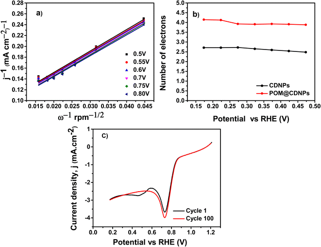
The Koutecky–Levich, (K–L) plots were used to evaluate the ORR kinetics at several potentials and estimate the electron transfer capacity of the POM@CDNPs. The fitting of the recorded LSV data at different rotation speeds using the K–L model is shown in Fig. 9. Fig. 9a, presented great linearity between j−1 vs. ω−1/2 at diverse potentials from 0.5 to 0.8 V, suggesting that ORR process a first-order kinetic reaction concerning the concentration of the dissolved O2.1,19 Based on the LSV measurements, the number of transferred electrons (n) per oxygen molecule was estimated by the K–L model, Fig. 9b. The n values of the CDNPs and POM@CDNPs at 0.17 V are 2.7, and 4.1, respectively. These results verify that POM@CDNPs behave in four-electron transfer pathways in the ORR process.
The stability of the POM@CDNPs electro-catalyst is a major parameter for evaluating the ORR performance. It was examined by chronoamperometry measurements at a scan rate of 50 mV s−1 and 3000 rpm for 100 cycles as shown in Fig. 9c. The sample achieved a high current density of −3.03 mA cm−2 after a 100 LSV working cycle with retention reaching about 99.9%.
Undoubtedly, the POM@CDNPs electro-catalyst manifests higher ORR catalytic activity in comparison with the published data in the same alkaline medium for POM composite materials, the higher current density is attained with good ORR process functionality and preferred four electrons transfer pathway Table 2.
4. Conclusions
A facile method was developed for the preparation of a nitrogen-doped-carbon xerogel/nanodiamond 3D matrix as a support material. Furthermore, the carbon/diamond support was functionalized by polyoxomolybdate through a hydrothermal reaction. The characterization techniques reveal a morphology transformation for the polyoxomolybdate from stacked two -dimensional aggregates into porous pyramidal structure onto the carbon/diamond matrix after the hydrothermal reaction. Moreover, a development in the pore diameter is observed for POM@CDNPs which enhances its oxygen adsorption capacity. Up on application as an electro-catalyst for the ORR, POM@CDNPs shows a limiting current density of −7.30 mA cm−2 at 0.17 V vs. RHE. Also, a half-wave potential of 0.773 V is delivered with stability reaching 99.9% after the 100th repetitive cycle in 0.1 M KOH. It is also noted that POM@CDNPs electro-catalyst forces the ORR to the direct-four-electron pathway which is the favoured one. These findings consider POM@CDNPs as an efficient catalyst for ORR with promising stability. The superior surface area of the carbon support is a crucial parameter in the electro-catalytic system, so the proposed future research work is studying the optimum carbon/diamond content that offers the highest surface area of the nanocomposite.Conflicts of interest
There are no conflicts to declare.References
- D. M. Fernandes, H. C. Novais, R. Bacsa, P. Serp, B. Bachiller-Baeza, I. Rodríguez-Ramos, A. Guerrero-Ruiz and C. Freire, Langmuir, 2018, 34, 6376–6387 CrossRef CAS PubMed.
- K. Rajeshwar, J. Ibanez and G. Swain, J. Appl. Electrochem., 1994, 24, 1077–1091 CrossRef CAS.
- X. Zhao, Q. Zhang, X. Huang, L. Ding, W. Yang, C. Wang and Q. Pan, Int. J. Hydrogen Energy, 2022, 47, 2178–2186 CrossRef CAS.
- Y.-J. Wang, N. Zhao, B. Fang, H. Li, X. T. Bi and H. Wang, Chem. Rev., 2015, 115, 3433–3467 CrossRef CAS PubMed.
- X. Huang, Z. Zhao, L. Cao, Y. Chen, E. Zhu, Z. Lin, M. Li, A. Yan, A. Zettl and Y. M. Wang, Science, 2015, 348, 1230–1234 CrossRef CAS PubMed.
- P. Mani, R. Srivastava and P. Strasser, J. Power Sources, 2011, 196, 666–673 CrossRef CAS.
- D. Banham, S. Ye, K. Pei, J.-i. Ozaki, T. Kishimoto and Y. Imashiro, J. Power Sources, 2015, 285, 334–348 CrossRef CAS.
- A. Elmouwahidi, J. F. Vivo-Vilches, A. F. Pérez-Cadenas, F. J. Maldonado-Hódar and F. Carrasco-Marín, Chem. Eng. J., 2016, 306, 1109–1115 CrossRef CAS.
- L. Dai, Y. Xue, L. Qu, H.-J. Choi and J.-B. Baek, Chem. Rev., 2015, 115, 4823–4892 CrossRef CAS PubMed.
- J. Masa, A. Zhao, W. Xia, M. Muhler and W. Schuhmann, Electrochim. Acta, 2014, 128, 271–278 CrossRef CAS.
- W. Yang, X. Liu, H. Lv and J. Jia, J. Colloid Interface Sci., 2021, 583, 371–375 CrossRef CAS PubMed.
- H.-J. Niu, S.-Y. Lin, Y.-P. Chen, J.-J. Feng, Q.-L. Zhang and A.-J. Wang, Appl. Surf. Sci., 2021, 536, 147950 CrossRef CAS.
- C. Wan, X. Duan and Y. Huang, Adv. Energy Mater., 2020, 10, 1903815 CrossRef CAS.
- H. Osgood, S. V. Devaguptapu, H. Xu, J. Cho and G. Wu, Nano Today, 2016, 11, 601–625 CrossRef CAS.
- X. Zhou, J. Qiao, L. Yang and J. Zhang, Adv. Energy Mater., 2014, 4, 1301523 CrossRef.
- N. I. Andersen, A. Serov and P. Atanassov, Appl. Catal., B, 2015, 163, 623–627 CrossRef CAS.
- F. Dehghani Sanij, P. Balakrishnan, H. Su, L. Khotseng and Q. Xu, RSC Adv., 2021, 11, 39118–39129 RSC.
- D. Zhang, T. Liu, C. An, H. Liu and Q. Wu, Mater. Lett., 2020, 262, 126954 CrossRef CAS.
- S. B. Ingavale, I. Patil, H. Parse, D. C. Sesu, P. Marbaniang, N. Ramgir, B. Kakade and A. Swami, Int. J. Hydrogen Energy, 2019, 44, 24922–24933 CrossRef CAS.
- S. Ingavale, I. Patil, K. Prabakaran and A. Swami, Int. J. Energy Res., 2021, 45, 7366–7379 CrossRef CAS.
- S. Zhang, R. Liu, S. Li, A. Dolbecq, P. Mialane, L. Suo, L. Bi, B. Zhang, T. Liu, C. Wu, L. Yan, Z. Su, G. Zhang and B. Keita, J. Colloid Interface Sci., 2018, 514, 507–516 CrossRef CAS PubMed.
- M. Nunes, D. M. Fernandes, I. M. Rocha, M. F. R. Pereira, I.-M. Mbomekalle, P. de Oliveira and C. Freire, ChemistrySelect, 2016, 1, 6257–6266 CrossRef CAS.
- E. Bailón-García, F. Carrasco-Marín, A. F. Pérez-Cadenas and F. J. Maldonado-Hódar, Catal. Commun., 2015, 58, 64–69 CrossRef.
- G. Y. Lee, I. Kim, J. Lim, M. Y. Yang, D. S. Choi, Y. Gu, Y. Oh, S. H. Kang, Y. S. Nam and S. O. Kim, J. Mater. Chem. A, 2017, 5, 1941–1947 RSC.
- H. Tian, J. Luo, K. Zhang, C. Ma, Y. Qi, S. Zhan, X. Liu, M. Li and H. Liu, Nanoscale Res. Lett., 2021, 16, 163 CrossRef CAS PubMed.
- A. Farhadipour, M. H. Alizadeh and H. Eshghi, Inorg. Chem. Commun., 2014, 41, 37–42 CrossRef CAS.
- A. Jarrah and S. Farhadi, RSC Adv., 2020, 10, 39881–39893 RSC.
- Z. Feng, G. Li, X. Wang, C. J. Gómez-García, J. Xin, H. Ma, H. Pang and K. Gao, Chem. Eng. J., 2022, 445, 136797 CrossRef CAS.
- H. Dong, W. Li, Y. Ou, D. Gao, Y. Yang, Y. Zhang and P. Xiao, Langmuir, 2020, 36, 4454–4464 CrossRef CAS PubMed.
- N. Wang, Y. Zhou, S. Yousif, T. Majima and L. Zhu, ACS Appl. Mater. Interfaces, 2019, 11, 34430–34440 CrossRef CAS PubMed.
- A. Enaiet Allah, H. Tan, X. Xu, A. A. Farghali, M. H. Khedr, A. A. Alshehri, Y. Bando, N. A. Kumar and Y. Yamauchi, Nanoscale, 2018, 10, 12398–12406 RSC.
- X. Xing, R. Liu, K. Cao, U. Kaiser, G. Zhang and C. Streb, ACS Appl. Mater. Interfaces, 2018, 10, 44511–44517 CrossRef CAS PubMed.
- I. S. Amiinu, Z. Pu, X. Liu, K. A. Owusu, H. G. R. Monestel, F. O. Boakye, H. Zhang and S. Mu, Adv. Funct. Mater., 2017, 27, 1702300 CrossRef.
- R. Liu, K. Cao, A. H. Clark, P. Lu, M. Anjass, J. Biskupek, U. Kaiser, G. Zhang and C. Streb, Chem. Sci., 2020, 11, 1043–1051 RSC.
- M. R. Horn, A. Singh, S. Alomari, S. Goberna-Ferrón, R. Benages-Vilau, N. Chodankar, N. Motta, K. Ostrikov, J. MacLeod, P. Sonar, P. Gomez-Romero and D. Dubal, Energy Environ. Sci., 2021, 14, 1652–1700 RSC.
- Y. Ji, L. Huang, J. Hu, C. Streb and Y.-F. Song, Energy Environ. Sci., 2015, 8, 776–789 RSC.
- R. Liu, Z. Xian, S. Zhang, C. Chen, Z. Yang, H. Li, W. Zheng, G. Zhang and H. Cao, RSC Adv., 2015, 5, 74447–74456 RSC.
Footnote |
| † Electronic supplementary information (ESI) available. See DOI: https://doi.org/10.1039/d2ra07543a |
| This journal is © The Royal Society of Chemistry 2023 |


