
 Open Access Article
 This Open Access Article is licensed under a Creative Commons Attribution-Non Commercial 3.0 Unported Licence
Charge-transport kinetics of dissolved redox-active polymers for rational design of flow batteries†
Kan Hatakeyama-Sato *,
Yuto Igarashi and
Kenichi Oyaizu*
*,
Yuto Igarashi and
Kenichi Oyaizu*
Department of Applied Chemistry, Waseda University, 3-4-1 Okubo, Shinjuku, Tokyo 169-8555, Japan. E-mail: oyaizu@waseda.jp; satokan@toki.waseda.jp
First published on 22nd December 2022
Abstract
Charge-transport kinetics of redox-active polymers is essential in designing electrochemical devices. We formulate the homogeneous and heterogeneous charge-transfer processes of the redox-active polymers dissolved in electrolytes. The critical electrochemical parameters, the apparent diffusion coefficient of charge transport (Dapp) and standard electrochemical reaction constant (k0), are estimated by considering the physical diffusion Dphys of polymer chains (Dapp, k0 ∝ Dphys). The models are validated with previously reported compounds and newly synthesized hydrophilic macromolecules. Solution-type cells are examined to analyze their primary responses from the electrochemical viewpoints.
Introduction
Redox-active polymers, offering reversible oxidation/reduction reactions as macromolecules, have been widely examined as essential components of organic electrochemical devices, such as rechargeable batteries, sensors, chromic devices, and actuators.1 In the last years, the urgent demand for sustainable technology highlighted polymers, especially as the active materials of secondary batteries.1–3 Their ecologically friendly, molecularly designable, and processable advantages are believed to support future energy systems by compensating for drawbacks of inorganic materials.1–3Redox-flow battery is one of the promising applications of organic redox-active materials.4–8 The batteries contain two tanks containing active materials, flow pumps, and electrochemical cells. Their scalable configuration is favored to store large electricity facilely. The devices can compensate for the fluctuating power generation of renewable energies, such as solar panels and wind farms.4 Although vanadium-based batteries are commercialized, the cost of vanadium and unsafe sulfuric acid solution as electrolytes are inherent problems.4
Versatile redox-active species, including 2,2,6,6-tetramethylpiperidine-1-oxyl (TEMPO), phenazine, viologen, anthraquinone, and imide compounds, have been proposed as organic active materials.4 Their robust redox reactions have been observed even with brine as the safe electrolyte.4,9 Some prototype cells exhibited an excellent cyclability over 1000, offering the promising potential for practical applications.4,9
Organic flow batteries are often designed using small redox-active molecules (molecular weight of around 102) because of their synthetic easiness and fast diffusion in electrolytes.9 Although even commercialized flow cells use small molecules (vanadium complexes),10 they can easily permeate through separators (crossover reaction).4–6 After reaching the opposite side, oxidized (or reduced) redox-active molecules will be reduced (oxidized) by reacting with charged anolytes (or catholytes) or at current collectors. The subsequent processes induce self-discharging and irreversible capacity loss.4–6 The issue is usually avoided by electrostatic repulsion: charged groups are attached to molecules and separators.9 However, the effect is not always perfect because the electrical charges of ions are shielded by solvents.11–13
Polymer design of active materials can be a fundamental solution to crossover.4 If the molecular weights are sufficiently large, their hydrodynamic radii will be larger than the free volume of electrolyte membranes or even the pore sizes of porous separators.4 Ultimately, crosslinked polymer particles were also examined to fix the large polymer shape.5,14
A drawback of polymer-based active materials is their slower electrochemical kinetics. The standard electrochemical reaction rate constant k0 and apparent diffusion coefficient for charge transport Dapp are several orders more minor than the corresponding monomeric species. The typical values of k0 = 10−3 to 10−5 cm s−1 and Dapp = 10−7 to 10−9 cm2 s−1 were reported with polymers, which are much smaller than molecules (k0 = 10−1 to 10−2 cm s−1 and Dapp 10−5 to 10−6 cm2 s−1).4–6,9,14
Regardless of the history of electrochemistry and polymer chemistry, the reason for the decrease has been unclear. The larger hydrodynamic radii may reduce Dapp,4–6,9,14–16 but the relation to actual physical diffusion behavior has been ambiguous. Further, no rational explanation was available for the decrease in k0; it was partially clarified with limited polymer systems of gels,17 but not sufficiently with dissolved polymers. For the rational design of electrochemical cells, those responses must be quantified.
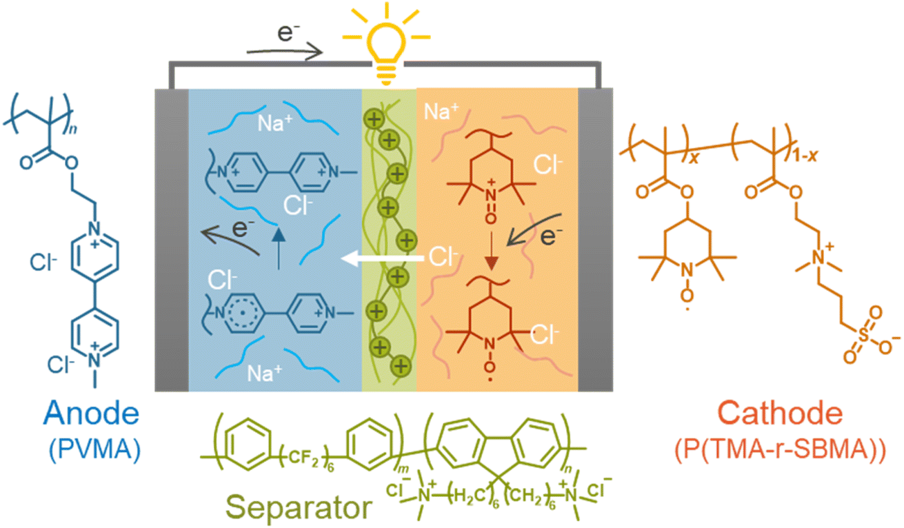
In this study, we formulated the electrochemical charge-transfer kinetics of dissolved redox-active polymers, focusing on the physical mobility of the active materials. The two kinetic parameters were regularly proportional to the physical diffusion coefficient of macromolecular chains. The model was valid with experimental literature data and newly synthesized polymers regardless of molecular structures. Finally, a prototype cell was fabricated using redox-active polyelectrolytes and an anion-exchange separator membrane. The benefit of the polymer-based active materials was demonstrated by suppressing unfavorable permeation reactions by electrostatic repulsions between the polymers (crossover of less than 1% after 10 days, Fig. 1).
 | ||
| Fig. 1 Configuration of the rechargeable cell examined in this study. | ||
Deriving apparent diffusion coefficient (Dapp) from physical diffusion
There are two essential electrochemical parameters in kinetics: apparent diffusion coefficient of charge-transfer Dapp and standard electrochemical reaction rate constant k0.3,17 The coefficient Dapp represents how fast the charge is transported in the solution under Fick's law.17 Another parameter, reaction rate constant, k0, is related to the electrode reaction rates, where the Butler–Volmer equation dominates the potential–current relationship.14Charge flux by redox-active materials, including monomeric and polymeric species, consists of two contributions, normal physical diffusion (Dphys) and electron self-exchange reactions (Det).16,17 Based on the self-exchange reactions, electrons “hop” among the redox-active sites, inducing diffusion-like charge flux (Fig. 2a).3,16,17
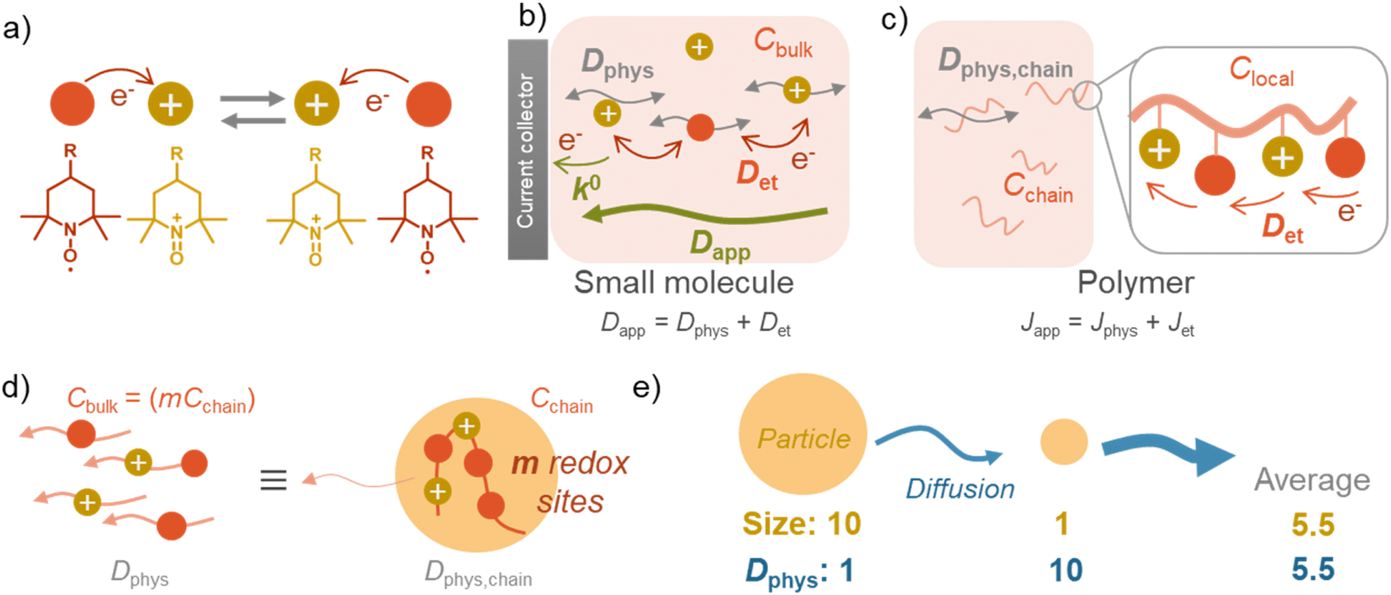 | ||
| Fig. 2 Scheme of charge transfer. (a) Electron self-exchange reaction by redox-active species, such as TEMPO. (b) Charge diffusion by small molecules. (c) Charge diffusion by polymers. (d) Approximation of a redox-active polymeric chain as small molecules. (e) Scheme of charge diffusion by two particles. Their average diffusion coefficient is 5.5, which never matches the value derived from average radii: 10/(average radii) = 10/5.5 = 1.8. | ||
In the case of small molecules, simple relation holds among the diffusion coefficient (eqn (1), Fig. 2b).5,14,16,18
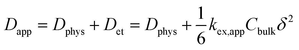 | (1) |
The second line clarifies the contribution of the electron self-exchange reaction, using the terms of its rate constant kex,app, molecular concentration Cbulk, and hopping distance δ.16,17
The simple formula may not be appropriate for the polymer systems dissolved (and dispersed) in solutions. The main reason is the heterogeneous distribution of redox-active moieties, densely introduced in polymer chains.5 Instead of diffusion coefficient, charge flux J can be discussed, considering the translational diffusion of polymer chains Jphys and local (intra- and inter-chain) electron hopping Jet (eqn (2), Fig. 2c).5
| Japp = Jphys + Jet = −mDphys,chain∇Cchain + −Det∇Clocal | (2) |
The electron transfer (Jet) is achieved via intra- and inter-chain electron hopping,19 where those contributions can be much minor to physical diffusion (see ESI† for further discussion). Ignorance of the electron hopping from eqn (2) yields a more straightforward relationship between the diffusion coefficients, Dphys and Dapp. If a polymer chain has m redox-active sites, the total concentration of redox-active species (Cbulk) becomes equal to mCchain. The total flux matches with an imaginary system, where small molecules dissolved in solution diffuse under the diffusion coefficient of Dphys,chain (eqn (3), Fig. 2d).
| Japp ≅ Jphys = −mDphys,chain∇Cchain = −Dphys,chain∇Cbulk | (3) |
In short, the diffusion of redox-active polymers may be approximated as homogeneously dissolved small molecules having the same diffusion coefficient (eqn (4))4,6,14,20
| Dapp ≅ Dphys,chain = Dphys | (4) |
Effects of hydrodynamic radii distribution for charge transport
The essential parameter for charge diffusion is the physical diffusion coefficient of molecules Dphys (eqn (4)). The coefficient is related to the Stokes–Einstein equation, applicable to wide molecular species, such as monomers, oligomers, polymers, and particles (eqn (5)).5,21 The equation is generally valid for various electrolyte conditions, including concentrated systems, because the contributions of solvent viscosity, temperature, and extension of macromolecular chains are considered.5,21
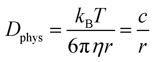 | (5) |
In contrast to monomeric species, polymers have a distribution of molecular weights, which provides the distribution of hydrodynamic radii during DLS. Commonly, the average molecular radius  estimated by dynamic light scattering (DLS), is used to calculate Dphys,chain.4,6,11,12,22–24 The technique has been employed to determine the physical diffusion of both dissolved and gel systems.17,25 According to the Stokes–Einstein equation, the average diffusion coefficient can also be calculated by integrating its different radius (r) contributions and probability p(r) (eqn (6)).
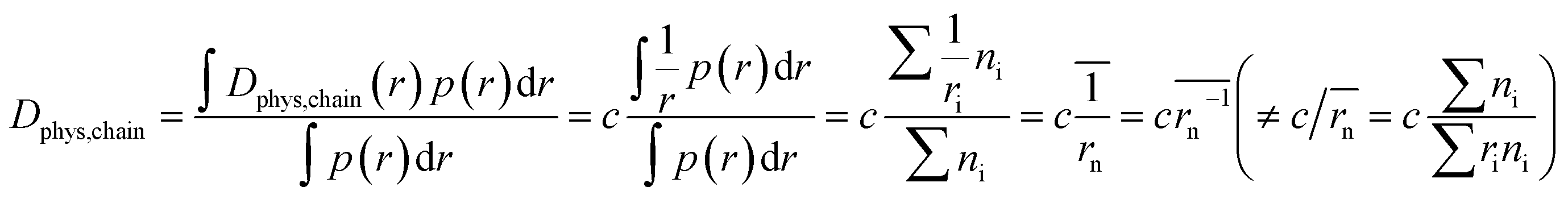 | (6) |
The calculation means that the number average of the inverse radius  could be more precise than the number-averaged hydrodynamic radius
 does not strictly match the number average of the inverse radius
  inducing the slight estimation error of Dphys,chain (Fig. 2e, see ESI† for details).
Derivation of electrode reaction rate constant (k0)
Another essential process, heterogeneous charge transfer between the active materials and the current collector, can also be formulated by a kinetic model. Our previous study on non-conjugated redox-active polymers proposed a diffusion-cooperated model for the standard electrode reaction rate constant k0 (eqn (7)).17
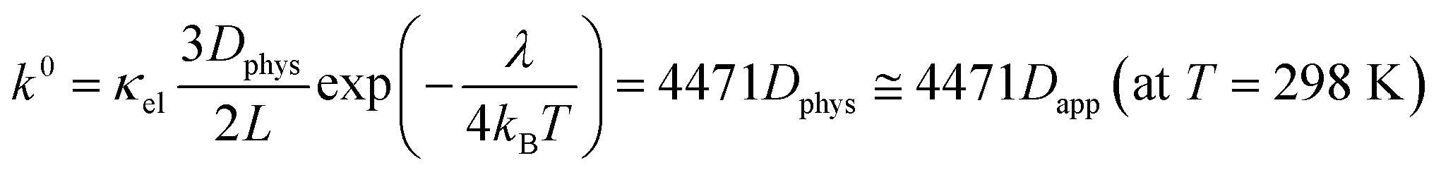 | (7) |
The model was valid for versatile organic active materials in different phases (e.g., gels and solutions). On the other hand, only limited cases were examined with dissolved species in electrolytes.17 This work will validate the model using our experimental results and literature values.
Even for k0, the essential term in the equation is Dphys. The collision frequency of the redox sites to the current collector dominates the electrode reaction. Other parameters, such as reorganization energy, are different among redox-active species, but their effects were not so significant as Dphys.17 Eqn (4), (6) and (7) will be checked with experimental results in the next section.
Experimental examination of Dapp and k0
We synthesized two redox-active polymers as potential candidates for flow batteries (Fig. 1). As the cathode, a hydrophilic random copolymer of TEMPO-substituted methacrylate and zwitterionic [2-(methacryloxy)ethyl]dimethyl-(3-sulfopropyl)ammonium hydroxide (P(TMA-r-SBMA))23 was synthesized. A compact viologen-substituted methacrylate monomer was polymerized via radical polymerization to obtain a new anode-active material (PVMA, Fig. S1 and S2†). The polymers were designed as polyelectrolytes for higher solubility in aqueous electrolytes (ca. 0.5 mol L−1 in water for the anode) to prevent crossover reactions through ionic membranes.The basic properties of the polymers were examined by static (and dynamic) light scattering (SLS, DLS), cyclic voltammetry, and rotating disk electrode (RDE)26 measurements (Fig. 3a–f). SLS revealed the absolute molecular weights of 9.0 × 10⁴ g mol−1 for P(TMA-r-SBMA) and 1.1 × 10⁴ g mol−1 for PVMA. Their hydrodynamic radii were estimated by DLS (Fig. 3a and c). The number-average radii  were estimated to be 8 and 2.5 nm for the cathode and anode polymers, respectively.
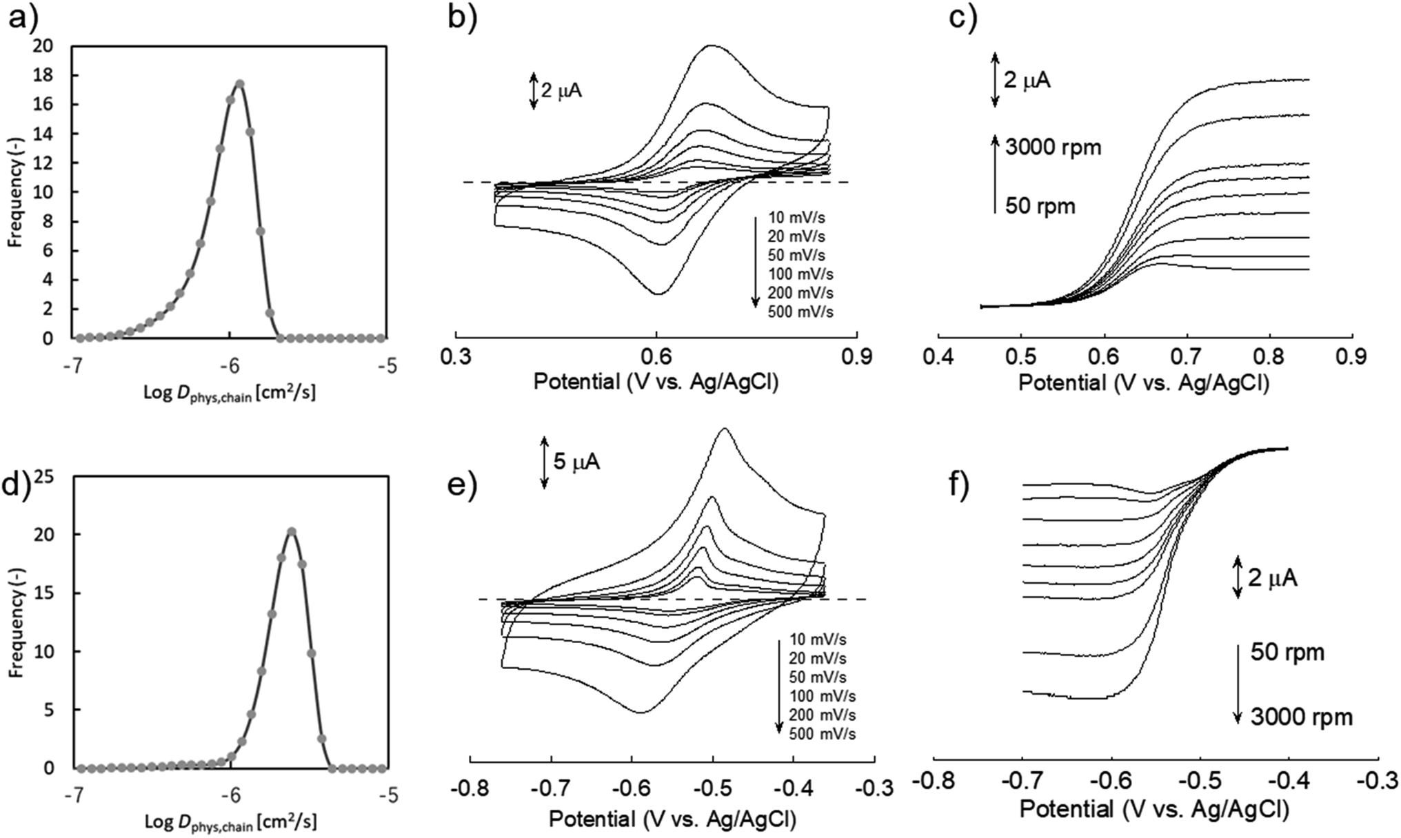 | ||
| Fig. 3 a) Distribution of physical diffusion coefficient of P(TMA-r-SBMA) in water, estimated by DLS. (b) Cyclic voltammograms of 2 mM polymer in 0.3 M NaCl aqueous solution with different scan rates. (c) Hydrodynamic voltammograms of 1 mM polymer in the electrolyte, scanned at 10 mV s−1. The electrode disk was rotated at 50, 100, 200, 400, 600, 1000, 2000, and 3000 rpm. (d) DLS, (e) cyclic voltammograms, and (f) hydrodynamic voltammograms of PVMA aqueous solution, measured under the same conditions. | ||
Dphys,chain calculated from eqn (6) was 1.0 × 10⁻⁶ and 2.3 × 10⁻⁶ cm2 s−1 for P(TMA-r-SBMA) and PVMA, respectively. The values slightly differed from the estimation from the conventional equation  0.56 × 10⁻⁶ and 2.0 × 10⁻⁶ cm2 s−1 (an example Excel sheet for the calculations available as ESI†). The current approach's estimated diffusion coefficient for the cathode was about twice that of the conventional one. Such strict treatment of the kinetic polymer parameters would be appreciated for accurate parameter evaluation.
Electrochemical measurements were conducted using a 0.3 M NaCl aqueous solution. During cyclic voltammetry, reversible redox reactions of TEMPO and viologen were detected at 0.64 and −0.54 V vs. Ag/AgCl for the cathode and anode, respectively (Fig. 3b and e). The polymers responded even at a high scan rate of 500 mV s−1 by their fast redox. Plateaus were detected during RDE, indicating the negligible effects of unfavorable side reactions such as polymer adsorption on electrode surfaces.6
Electrochemical parameters were estimated from cyclic voltammetry and RDE (Table 1). The linear relationship between the peak current and square of scan rate enabled the estimation of Dapp by Randles–Sevcik equation (Fig. S3†).27 Koutecký–Levich equation also estimated Dapp and k0 from the RDE results (Fig. S4†). We note that the RDE method contains some estimation errors for compounds with large k0 26 (see ESI† for further discussion).
| Entry | Type | Compound | Redox unit | log![[thin space (1/6-em)]](https://www.rsc.org/images/entities/char_2009.gif) Dphysa Dphysa |
logDappa |
logk0 (exp)b |
logk0 (calc)b |
Ref. |
|---|---|---|---|---|---|---|---|---|
| a Original unit of cm2 s−1. Dphys was estimated by DLS for polymeric species and by simulations for monomeric species. Dapp was evaluated by electrochemical methods. If not available in the literature, viscosity was assumed to be 0.89 and 0.74 mPa s (ref. 31) for aqueous and acetonitrile electrolytes.b Original unit of cm s−1. The calculated value was estimated by eqn (7).c Estimated by cyclic voltammetry.d This work.e Estimated by RDE. Results for entry 6 would contain errors because RDE curves did not provide plateaus in the diffusion-limited regions.f Structures are given in Fig. S8.g Determined by voltammetry using microdisk electrodes.h Estimated by Nicholson's method. | ||||||||
| 1 | Polymer | P(TMA-r-SBMA)c | TEMPO | −6.0 | −6.1 | — | −2.5 | —d |
| 2 | Polymer | P(TMA-r-SBMA)e | TEMPO | −6.0 | −6.4 | −2.9e | −2.8 | —d |
| 3 | Polymer | PVMAc | Viologen | −5.6 | −5.8 | — | −2.1 | —d |
| 4 | Polymer | PVMAe | Viologen | −5.6 | −6.3 | −2.7e | −2.6 | —d |
| 5 | Polymer | C1f | TEMPO | −7.2 | −7.2 | −3.3e | −3.5 | 6 |
| 6 | Polymer | C2f | Viologen | −6.7 | (−6.1) | (−4.0)e | −2.5 | 6 |
| 7 | Polymer | C3f | TEMPO | −6.0 | −6.4 | −3.0e | −2.8 | 23 |
| 8 | Polymer | C4f | TEMPO | — | −6.8 | −3.0e | −3.1 | 22 |
| 9 | Polymer | C5f | TEMPO | — | −6.7 | −3.2e | −3.1 | 28 |
| 10 | Oligomer | C6f | Nitrobenzene | — | −5.3 | −2.9g | −1.7 | 29 |
| 11 | Oligomer | C7f | TEMPO | — | −5.4 | −1.4g | −1.7 | 29 |
| 12 | Oligomer | C8f | Methoxyphenol | — | −5.5 | −2.4g | −1.9 | 29 |
| 13 | Oligomer | C9f | Cyclopropenium | — | −6.3 | −3.0h | −2.6 | 20 |
| 14 | Oligomer | C10f | Cyclopropenium | — | −6.0 | −2.8h | −2.3 | 20 |
| 15 | Oligomer | C11f | Cyclopropenium | — | −5.7 | −2.6h | −2.0 | 20 |
| 16 | Monomer | C12f | Cyclopropenium | −5.2 | −5.2 | −2.7h | −1.5 | 20 |
| 17 | Monomer | C13f | Viologen | −5.2 | −4.9 | — | −1.2 | 30 |
| 18 | Monomer | TEMPOLe | TEMPO | −5.1 | −5.1 | −1.6e | −1.5 | —d |
| 19 | Monomer | Viologene | Viologen | −5.2 | −5.2 | −1.5e | −1.5 | —d |
Slightly larger Dapp was obtained by cyclic voltammetry than RDE (e.g., 7.8 × 10⁻⁷ and 3.6 × 10⁻⁷ cm2 s−1, respectively, for the cathode). Non-faradaic capacitive current is suspected to increase the apparent current during cyclic voltammetry. As the control for the polymers, small redox-active molecules, 4-hydroxy TEMPO (TEMPOL) and ethylviologen, were also examined (Fig. S6 and S7†).
Comparison of experimental values with theoretical ones
The experimental constants were compared with values derived from equations. Theoretical Dapp and k0 were estimated from eqn (4), (6) and (7). For polymeric species, the number average of inverse radius was employed to calculate Dphys,chain. Molecular radii of small molecules were estimated from their van der Waals volume32 and sphere-shaped approximation.
Good agreements were observed between the experimental and estimated values (Fig. 4). For instance, the predicted logDapp of P(TMA-r-SBMA), −6.0, was almost comparable to the actual value from RDE, −6.4 (Table 1, entry 2). The estimated electrode constant logk0 of −2.8 matched the experimental value, −2.9 (entry 2). The equations were also valid for monomeric species. In the case of TEMPOL, the estimated logDapp and logk0 were −5.1 and −1.5, while the actual values were −5.1 and −1.6, respectively (entry 18).
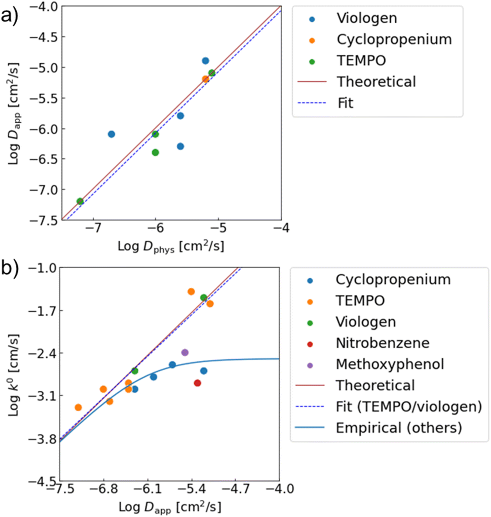 | ||
| Fig. 4 Relationships between (a) Dapp and Dphys, (b) k0 amd Dapp. Red lines show theoretical predictions from eqn (4) and (7). From experimental data, linear fittings were done. Dapp ∝ Dphys1.00 was obtained for the physical diffusion coefficients. For k0, the relationship of k0 ∝ Dapp0.97 was observed when only TEMPO and viologen were fitted. For the other redox sites with slower redox kinetics, an empirical law of eqn (8) was introduced to explain the trend. | ||
Our model was also valid with various redox-active compounds, including previously reported monomeric, oligomeric and polymeric compounds with different molecular designs (Table 1, Fig. 4 and S8†). The experimental relationship of Dapp ∝ Dphys1.00 was observed between the diffusion coefficients, corresponding to eqn (4) (Dapp = Dphys). The trend was comparable to the experimental results with monomeric species.18 Similarly, the experimental trend of k0 ∝ Dapp0.97 was observed with TEMPO- and viologen-based compounds, which almost matched the prediction of k0 = 4471Dapp (eqn (7)).
The prediction of the standard electrode reaction rate constant by eqn (7) was unsuccessful with several redox-active compounds of cyclopropenium, nitrobenzene, and methoxyphenol (Fig. 4b). One apparent reason was that the formula of k0 = 4471Dapp (eqn (7)) supposed only the fast redox systems with relatively small reorganization energy λ, corresponding to large k0 (e.g., 10−1 to 10−2 cm s−1 for TEMPO and viologen). On the other hand, the three redox units had smaller rate constants as monomeric species (k0 = 10−3 cm s−1),20 which was out of scope of the prediction.
Further, we observed an unexpected nonlinear trend with cyclopropenium species having different molecular weights (monomer species and oligomers, Fig. 4b, blue plots). The reorganization energy λ in eqn (7) should be almost identical with the cyclopropeniums, and thus a trend of k0 ∝ Dapp1.0 was expected. Nevertheless, the experimental relationship between k0 and Dapp was not linear, indicating that eqn (7) was not valid for these molecular species.
Here, a semi-empirical formula was introduced to explain k0 of the slower redox-active species, which could not be explained by eqn (7) (eqn (8)).
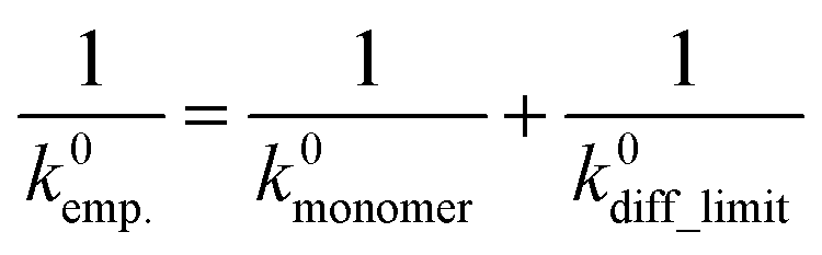 | (8) |
The equation assumed that the electrode reaction was a serial step of diffusion and electron transfer, in the same way as an electron self-exchange reaction.17 The first term of k0monomer corresponded to the electron transfer constant with fast diffusion (i.e., monomeric species). The second term of k0diff_limit was the constant for the diffusion-dominating processes, represented by eqn (7).
When we conveniently supposed the terms of k0monomer = 10−2 cm s−1 and k0diff_limit = 4471Dapp, the experimental trends for the three redox-active species were explained successfully (Fig. 4b, blue line). We emphasize that the equation and terms of k0monomer and k0diff_limit were determined heuristically. For more strict treatment, the reorganization energy in eqn (7) must be changed for the values of each redox species. Although the formulation was not strict, the match to the experimental data indicated the necessity to separate electron transfer and diffusion terms to predict the rate constant. The details should be revealed in future research on the electrochemistry of macromolecules.
Potential factors for errors in determining and predicting the rate constants must also be discussed. The experimental Dapp and k0 are known to contain measurement errors and to vary by a factor of >10 by different measurement methods, such as cyclic voltammetry, chronoamperometry, rotating disk electrode, microelectrode, and impedance (see ESI† for the estimation error by RDE).27,33 Estimation of Dphys also contains significant errors. DLS is available for macromolecules to estimate the exact Dphys. On the other hand, monomeric and oligomeric species are too small to detect by DSL, and computational methods should be introduced instead.
The simplification of the model will also induce prediction errors. For instance, the models did not consider inter-/intra-chain interaction, electron hopping, counter ion dynamics, solvent effects, and differences in reorganization energies.3,17,34 Aggregation of macromolecules during measurements or other unexpected interactions could be other possible reasons whereas, further discussion is difficult from the reported data.6
Our diffusion theory affords some guidelines for designing active materials. The general agreement of Dapp and k0 with the theoretical prediction meant the diffusion of redox-active species was essential for charge transport. Thus, increasing Dphys is critical to enhancing the kinetics of redox-active molecules. The apparent diffusion coefficient Dapp is essential to obtain a larger experimental capacity.4,6,14,20 Further, k0 should be large enough to reduce overvoltages under large C-rates, according to the Butler–Volmer equation.27
Polymer structures are beneficial for avoiding crossover reactions, but larger molecular weights induce smaller Dphys. The use of star-shaped, hyperbranched, or bottlebrush architecture35 should improve Dphys. Their dense and hard molecular design would decrease relative hydrodynamic radius and friction against solvents. The concept was preliminarily examined in our bottlebrush polymers,36 whereas a more extensive study is needed in future research.
Here, the kinetic parameters, proportional to Dphys, depend on viscosity and temperature according to the Stokes–Einstein equation (eqn (5)). Viscosity is also affected by the concentration of active materials. Most papers, including this work, focus on evaluating the variables under low concentrations (e.g., 1 mM). Measurements under concentrated conditions of actual flow systems are needed to evaluate the exact electrochemistry of devices.6,14,20,30
Charge/discharge properties of synthesized polymers
Finally, we examined P(TMA-r-SBMA) and PVMA as active materials of prototype batteries. An H-type cell was introduced as a simple configuration (Fig. 5a). An anion-exchange membrane of a robust perfluoroalkylene polymer with pendant ammonium groups37 was selected as the separator (Fig. 1). The polymer was developed for fuel cells with alkaline electrolytes, but was found to give promising properties with brine electrolytes. The observed conductivity (9.7 mS cm−1) was larger than a conventional polystyrene-based, anion-exchange membrane (SELEMION, 4.2 mS cm−1) and Nafion (6.0 mS cm−1, Fig. S9†). The membrane also offered a high Young's modulus of >20 MPa s, enabling the use as a thin film (30 μm).37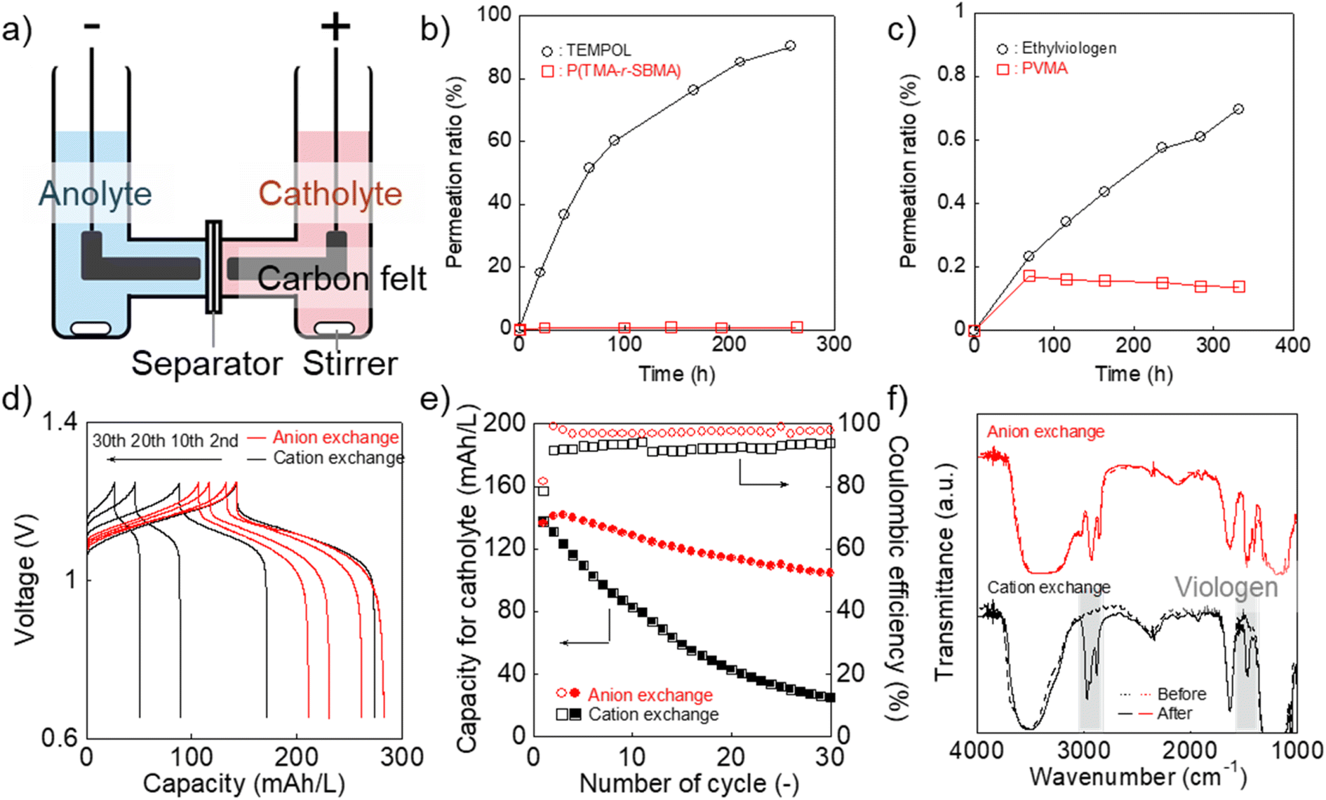 | ||
| Fig. 5 (a) Configuration of the H-type cell. (b) Permeation of the catholyte materials in water (2 mM) to pristine water through the anion-exchange membrane. (c) Results for the anolyte materials. (d) Charge/discharge curves for the H-type cell with the redox-active polymers and different separators (anion-exchange membrane37 or Nafion). Formal catholyte and anolyte capacities were 200 and 300 mA h L−1, respectively. The cell was operated at 0.5C. (e) Discharging capacity and coulombic efficiency at each cycle. (f) IR-spectra of the membranes after the battery test. | ||
The permeation rate of active materials was estimated by filling an aqueous polymer solution on one side and pristine water on the counter (Fig. 5b and c). After ten days, about 1% of P(TMA-r-SBMA) and 0.1% of PVMA moved into the counter side. The amounts were much smaller than TEMPOL (90%) and ethylviologen (0.7%), as control experiments. The smaller ratio with PVMA (0.1%) than P(TMA-r-SBMA) (1%) suggested the effect of electrostatic repulsion between the polycation separator and anode-active material to avoid crossover.
The diffusion coefficients for permeation were estimated using a steady-state diffusion model (Fig. S10–S12†). We described formal derivations for the model (see ESI†). The diffusion coefficients were estimated to be 6 × 10⁻¹² (P(TMA-r-SBMA)), 3 × 10⁻⁸ (TEMPOL), <1 × 10⁻¹² (PVMA), and 7 × 10⁻¹¹ cm2 s−1 (ethylviologen). Much smaller values were obtained with the cationic species than neutral TEMPOL because of the electrostatic repulsion against the polycation separator. The polymeric strategy was also essential to avoid permeation by their larger hydrodynamic radii.
A charge/discharge test was conducted by introducing P(TMA-r-SBMA) and PVMA as the catholyte and anolyte, respectively (Fig. 5d). The cell operated at 1.1 V, corresponding to the standard voltage of 1.18 V. The experimental charging capacity was 142 mA h L−1 against the theoretical value of 200 mA h L−1 (70%) at a rate of 0.5C. High coulombic efficiency of 99% was obtained owing to the reversible redox reactions of the active materials. Such near-ideal responses can be partially explained by the sufficiently large Dapp and k0 of the polymers (see Experimental section and ESI† for further discussion).38,39
The cell maintained 74% of the initial capacity after 30 charge/discharge cycles (Fig. 5d and e). We conducted charge/discharge measurements with three-electrode systems to analyze the reasons for the capacity decay (Fig. S13 and S14†). In the three-electrode systems, the capacity of the working side was not limited by the counter, which enabled more accessible analyses of capacity change. The discharge capacity after 30 cycles was as high as 96% of the initial value. The result indicated that electrode-active materials themselves were not degraded significantly. The total time for charging/discharging reactions was around (1/0.5C) × 2 × 30 times = 120 hours. During the period, the crossover was successfully suppressed with the synthesized polymers, while a large amount of 4-hydroxy TEMPO should have diffused to the opposite side (Fig. 5b and c).
Some reasons explain the capacity decay, such as leakage current by brine electrolysis, self-discharging by oxygen or other impurities, and side reactions. In principle, the reactions should be technically avoidable by optimizing cell conditions. We note that TEMPO and viologen derivatives can exhibit promising cyclability (>100–1000) in flow batteries.6,9 Main differences between this prototype cell and previous reports are, (a) smaller active material concentration (ca. 0.1 A h L−1 for this work and 10 A h L−1 for previous reports6,9) and (b) whether the system is flowed6,9 or not (this work). The smaller concentration of active materials leads to larger contributions of side reactions by impurity oxygen and water splitting. Flowing electrolytes is also essential to induce charge/discharge reactions more effectively. Mass synthesis of polymers is our future topic of study to examine the materials in the complete form of flow cells.
As a control experiment, we introduced a cation-exchange membrane (Nafion) as a conventional separator (Fig. 5d and e). Cation-exchange membranes are typically used for negatively charged active materials but are sometimes applied even to positively charged compounds, such as viologens.8 The initial capacity (143 mA h L−1) was almost identical to the anion-exchange membrane. However, the capacity gradually decreased to 26 mA h L−1 after 30 cycles with Nafion. The decrease was caused by the absorption of PVMA on Nafion (Fig. 5f and S15†). No spectral change was detected with the anion-exchange membrane before/after the charge/discharge measurement. In contrast, characteristic viologen peaks were detected at around 1500 and 3000 cm−1 in the case of Nafion. A macromolecular complex of Nafion and PVMA should have been formed in the film, and unfavorable absorption caused the decreased anolyte capacity.
Conclusion
We formulated charge-transfer kinetics of polymerized redox-active species in solutions. The diffusion-based kinetic model proposed two essential predictions. First, the apparent diffusion coefficient of charge transfer (Dapp) will match the physical diffusion coefficient of the active materials in solutions (Dphys). Second, the standard electrode reaction constant (k0) will be proportional to Dapp with a coefficient of ca. 4500 for the fast redox-responsible species such as TEMPO and viologen. Modification of the model was needed to explain k0 for molecules with slower electron transfer. The benefit of the polymer design was demonstrated by introducing polyelectrolyte-type, active materials. The electrostatic repulsion between the ionic polymers and an anion-exchange membrane avoided crossover reactions, giving good capacity retention of 74% after 30 charge/discharge cycles. Our next challenge is formulating polymer kinetics under highly concentrated conditions, considering the real flow battery systems with porous current collectors under flowed conditions.9Experimental section
Materials
NaOH and NH4PF6 were purchased from Fujifilm Wako Chemicals Co. HCl and Na2WO4·2H2O were obtained from Kanto Chemical Co. 2,2,6,6-Tetramethyl-4-piperidyl methacrylate, 3-[[2-(methacryloyloxy)ethyl]dimethylammonio]propane-1-sulfonate, thioglycolic acid, 4,4′-azobis(4-cyanovaleric acid), hydrogen peroxide, ethylviologen dibromide, 4,4′-bipyridyl, indomethane, 2-bromoethanol, methacryloyl chloride, triethylamine, hydroquinone and tetrabuthylammonium chloride were purchased from Tokyo Chemical Industry Co. Other chemicals were obtained from the above companies. All compounds were used as received. The anion-exchange membrane was obtained from Takahata precision Co. The membrane originally had methanesulfonate anions. Chloride polymers were obtained after immersing them in 1 M NaCl aqueous solution at 80 °C for 2 days. For control experiments, Nafion perfluorinated membrane (product number: 676470, thickness 0.002 inch) was purchased from Sigma-Aldrich Co., and SELEMION (anion-exchange membrane, product name: AMVN, chloride anions) was obtained from AGC Engineering Co. Nafion was immersed in 0.1 M NaOH aqueous solution overnight for neutralization.Synthesis of P(TMA-r-SBMA) (Scheme S1†)
000 rpm, 30 minutes). Then, ethanol/water mixture (80/20 in vol%) was added to dissolve excessive salt, and centrifuged at 10000 rpm for 12 minutes (repeat this process twice). The piperidine polymer was obtained after drying solvents. The polymerization ratio x was estimated to be around 0.5 by 1H-NMR.1H NMR (500 MHz, D2O, δ): 5.19 (br, 1H, OCH), 4.56 (br, 2H, OCH2), 3.87 (br, 2H, OCH2CH2), 3.67 (br, 2H, N+CH2CH2CH2SO3−), 3.29 (br, 6H, N+(CH3)2), 3.02 (br, 2H, N+CH2CH2CH2SO3−), 2.33 (br, 2H, N+CH2CH2CH2SO3− and backbone), 2.33–1.81 (br, 4H, OCHCH2 and backbone), 1.52 (br, 12H, NC(CH3)2), 1.19–0.98 (br, backbone).
Synthesis of PVMA (Scheme S2†)
1H NMR (500 MHz, D2O, δ): 8.92 (d, 2H, J = 6 Hz, α-pyridinium), 8.78 (d, 2H, J = 5 Hz, β-pyridinium), 8.40 (d, 2H, J = 6 Hz, α-pyridine), 7.92 (d, 2H, J = 5 Hz, β-pyridine), 4.46 (s, 3H, CH3). 13C NMR (500 MHz, D2O, δ): 153.6, 150.0, 145.7, 142.7, 125.9, 122.5, 47.9. FAB-MS (m/z): 171.2 (calculated), 170.8 (found).
1H NMR (500 MHz, CDCl3, δ): 6.17 (s, 1H, allyl on the C![[double bond, length as m-dash]](https://www.rsc.org/images/entities/char_e001.gif) O side), 5.62 (s, 1H, allyl on the CH3 side), 4.46 (t, 2H, J = 6, 6.5 Hz, OCH2), 3.56, (t, 2H, J = 5, 6 Hz, CH2Br), 1.97 (s, 3H, CH3). 13C NMR (500 MHz, D2O, δ): 166.9, 135.9, 126.4, 64.0, 28.8, 18.3. FAB-MS (m/z): 191.98 (calculated), 192.2 (found).
O side), 5.62 (s, 1H, allyl on the CH3 side), 4.46 (t, 2H, J = 6, 6.5 Hz, OCH2), 3.56, (t, 2H, J = 5, 6 Hz, CH2Br), 1.97 (s, 3H, CH3). 13C NMR (500 MHz, D2O, δ): 166.9, 135.9, 126.4, 64.0, 28.8, 18.3. FAB-MS (m/z): 191.98 (calculated), 192.2 (found).
1H NMR (500 MHz, D2O, δ): 9.24 (d, 2H, J = 7 Hz, α-bipyridinium on the methacrylate side), 9.08 (d, 2H, J = 6.5 Hz, α-bipyridinium on the CH3 side), 8.61 (d, 2H, J = 6.5 Hz, β-bipyridinium on the CH3 side), 8.55 (d, 2H, J = 6 Hz, β-bipyridinium on the methacrylate side), 6.12 (s, 1H, allyl on the CO side), 5.76 (s, 1H, allyl on the CH3 side), 5.13 (t, 2H, J = 5, 5 Hz, OCH2), 4.53 (s, 3H, CH3 of the bipyridinium), 1.88 (s, 3H, CH3 of the methacrylate). 13C NMR (500 MHz, D2O, δ): 168.5, 151.0, 146.4, 146.1, 135.0, 127.9, 127.1, 126.8, 63.0, 60.6, 48.5, 17.3. FAB-MS (m/z): 284.36 (calculated), 284.1 (found).
1H NMR (500 MHz, D2O, δ): 9.30 (br, 2H, α-bipyridinium on the methacrylate side), 9.10 (br, 2H α-bipyridinium on the CH3 side), 8.72 (br, 2H, β-bipyridinium on the CH3 side), 8.62 (br, 2H, β-bipyridinium on the methacrylate side), 5.15 (br, 2H, OCH2), 4.53 (br, 3H, CH3 of the bipyridinium).
Measurements
Dissolved polymers in water were measured by SLS and DLS with Malvern ZETASIZER NANO-ZS. IR measurements were conducted using FT/IR-6100 (JASSO). UV-Vis spectra were recorded by V-670 (JASSO).Electrochemical measurements
Electrochemical measurements were conducted under a nitrogen atmosphere. Electrochemical measurements were performed by a conventional potentiostat (BAS ALS 660D). A platinum coil as a counter electrode and an Ag/AgCl wire as a reference were introduced for three-electrode measurements. A glassy carbon disk electrode (diameter of 1.6 mm) was used as working during cyclic voltammetry. A glassy carbon disk (diameter of 3 mm) was used as working during RDE. 0.3 M NaCl aqueous solution was introduced unless noted otherwise.Battery test
Catholyte and anolyte were prepared by dissolving P(TMA-r-SBMA) (200 mA h L−1) and PVMA (300 mA h L−1) in the brine electrolyte, respectively. The liquids (3.5 mL) were separated by an anion-exchange membrane37 in an H-type cell. Stirring bars were employed to mix the solution. Carbon felts (EC Frontier Co.) were introduced as current collectors. The effective area of the separator was 0.5 cm2.Permeation test of active materials
An H-type cell was introduced for permeation tests, whose configuration is shown in Fig. S11.† On one side, 2 mM active material in water was filled with a volume of 4 mL. On the opposite side, pristine water was filled with the same amount. The two vials were joined with an anion-exchange membrane and fixed by screws. The effective area of the membrane A was 0.5 cm2, and its thickness d was 0.03 mm.The integrated cell was stirred for several days to induce permeation. Periodically, a small amount of the liquid on the counter side was sampled. A UV-Vis spectrometer estimated the concentration of active materials in the liquids (Fig. S10†). Calibration lines of TEMPOL and ethylviologen, displaying characteristic absorption peaks of TEMPO (237 nm) and viologen (262 nm), were used to quantify the amount. After estimating the concentrations, their time dependencies were fitted by a theoretical equation of diffusion,  which was derived in the ESI† (C1: concentration of the active material side, C0 = 2 mM, Dperm: diffusion coefficient, and t: time, Fig. S12†). In Fig. 5b and c, the permeation ratio was defined as (estimated molar concentration of the active material)/(1 mM) × 100 %.
Ionic conductivity measurement
Ionic conductivities of the separators were estimated using an impedance spectrometer, Solartron 1260 Impedance/Gain-Phase Analyzer. The separators were immersed in 0.3 M NaCl aqueous solution and sandwiched by stainless disks with a diameter of 1 cm. Their impedance spectra were measured using the analyzer.Estimation of Dphys for monomeric and oligomeric species
In Table 1 and Fig. 4, Dphys for monomeric species were estimated using simulations. van der Waals volume (V) was calculated according to a previous report.32 Then, their radii were estimated under the sphere-shaped assumption Stokes–Einstein equation (eqn (5)) with yielded Dphys.
Fitting experimental parameters
In Fig. 4, experimental trends of kinetic parameters were fitted by a linear model. An open-source library of scikit-learn (version 0.23.2) was introduced for the data analysis.40 A HuberRegressor was employed to fit the data because of the robustness against the outliers.40Author contributions
All authors have given approval for the final version of the manuscript.Conflicts of interest
There are no conflicts to declare.Acknowledgements
This work was partially supported by Grants-in-Aid for Scientific Research (No. 21H04695, 21H02017, 22H04623, and 20H05298) from the Ministry of Education, Culture, Sports, Science and Technology, Japan. The work was partially supported by JST FOREST Program (Grant Number JPMJFR213V, Japan) and the Research Institute for Science and Engineering, Waseda University. This work was partially supported by Alkali Energy Device Project of Takahata Co. and Waseda University.Notes and references
- J. Kim, J. H. Kim and K. Ariga, Joule, 2017, 1, 739–768 CrossRef CAS.
- Y. Xie, K. Zhang, Y. Yamauchi, K. Oyaizu and Z. Jia, Mater. Horiz., 2021, 8, 803–829 RSC.
- S. Y. Wang, A. D. Easley and J. Lutkenhaus, ACS Macro Lett., 2020, 9, 358–370 CrossRef CAS PubMed.
- Y. Y. Lai, X. Li and Y. Zhu, ACS Appl. Polym. Mater., 2020, 2, 113–128 CrossRef CAS.
- K. Hatakeyama-Sato, T. Nagano, S. Noguchi, Y. Sugai, J. Du, H. Nishide and K. Oyaizu, ACS Appl. Polym. Mater., 2019, 1, 188–196 CrossRef CAS.
- T. Janoschka, N. Martin, U. Martin, C. Friebe, S. Morgenstern, H. Hiller, M. D. Hager and U. S. Schubert, Nature, 2015, 527, 78–81 CrossRef CAS PubMed.
- P. Navalpotro, J. Palma, M. Anderson and R. Marcilla, Angew. Chem., Int. Ed., 2017, 56, 12460–12465 CrossRef CAS PubMed.
- A. Ohira, T. Funaki, E. Ishida, J.-D. Kim and Y. Sato, ACS Appl. Energy Mater., 2020, 3, 4377–4383 CrossRef CAS.
- J. Luo, B. Hu, M. Hu, Y. Zhao and T. L. Liu, ACS Energy Lett., 2019, 4, 2220–2240 CrossRef CAS.
- T. N. L. Doan, T. K. A. Hoang and P. Chen, RSC Adv., 2015, 5, 72805–72815 RSC.
- T. Hagemann, J. Winsberg, M. Grube, I. Nischang, T. Janoschka, N. Martin, M. D. Hager and U. S. Schubert, J. Power Sources, 2018, 378, 546–554 CrossRef CAS.
- T. Janoschka, N. Martin, M. D. Hager and U. S. Schubert, Angew. Chem., Int. Ed., 2016, 55, 14427–14430 CrossRef CAS PubMed.
- L. J. Small, H. D. Pratt and T. M. Anderson, J. Electrochem. Soc., 2019, 166, A2536–A2542 CrossRef CAS.
- E. C. Montoto, G. Nagarjuna, J. Hui, M. Burgess, N. M. Sekerak, K. Hernandez-Burgos, T. S. Wei, M. Kneer, J. Grolman, K. J. Cheng, J. A. Lewis, J. S. Moore and J. Rodriguez-Lopez, J. Am. Chem. Soc., 2016, 138, 13230–13237 CrossRef CAS PubMed.
- T. W. Smith, J. E. Kuder and D. Wychick, J. Polym. Sci., Polym. Chem. Ed., 1976, 14, 2433–2448 CrossRef CAS.
- R. W. Murray, Molecular Design of Electrode Surfaces, Wiley- Interscience, New York, 1992 Search PubMed.
- K. Sato, R. Ichinoi, R. Mizukami, T. Serikawa, Y. Sasaki, J. Lutkenhaus, H. Nishide and K. Oyaizu, J. Am. Chem. Soc., 2018, 140, 1049–1056 CrossRef CAS PubMed.
- G. Grampp and K. Rasmussen, Phys. Chem. Chem. Phys., 2002, 4, 5546–5549 RSC.
- T. W. Kemper, T. Gennett and R. E. Larsen, J. Phys. Chem. C, 2016, 120, 25639–25646 CrossRef CAS.
- K. H. Hendriks, S. G. Robinson, M. N. Braten, C. S. Sevov, B. A. Helms, M. S. Sigman, S. D. Minteer and M. S. Sanford, ACS Cent. Sci., 2018, 4, 189–196 CrossRef CAS PubMed.
- J. T. Edward, J. Chem. Educ., 1970, 47, 261 CrossRef CAS.
- J. Winsberg, T. Janoschka, S. Morgenstern, T. Hagemann, S. Muench, G. Hauffman, J. F. Gohy, M. D. Hager and U. S. Schubert, Adv. Mater., 2016, 28, 2238–2243 CrossRef CAS PubMed.
- T. Hagemann, M. Strumpf, E. Schröter, C. Stolze, M. Grube, I. Nischang, M. D. Hager and U. S. Schubert, Chem. Mater., 2019, 31, 7987–7999 CrossRef CAS.
- T. Janoschka, S. Morgenstern, H. Hiller, C. Friebe, K. Wolkersdörfer, B. Häupler, M. D. Hager and U. S. Schubert, Polym. Chem., 2015, 6, 7801–7811 RSC.
- T. Sakai, T. Matsunaga, Y. Yamamoto, C. Ito, R. Yoshida, S. Suzuki, N. Sasaki, M. Shibayama and U. I. Chung, Macromolecules, 2008, 41, 5379–5384 CrossRef CAS.
- F. J. Vidal-Iglesias, J. Solla-Gullón, V. Montiel and A. Aldaz, Electrochem. Commun., 2012, 15, 42–45 CrossRef CAS.
- J. B. Allen and R. F. Larry, Electrochemical Methods: Fundamentals and Applications, John Wiley & Sons, 2nd edn, 2001 Search PubMed.
- J. Winsberg, S. Muench, T. Hagemann, S. Morgenstern, T. Janoschka, M. Billing, F. H. Schacher, G. Hauffman, J.-F. Gohy, S. Hoeppener, M. D. Hager and U. S. Schubert, Polym. Chem., 2016, 7, 1711–1718 RSC.
- M. J. Baran, M. N. Braten, E. C. Montoto, Z. T. Gossage, L. Ma, E. Chénard, J. S. Moore, J. Rodríguez-López and B. A. Helms, Chem. Mater., 2018, 30, 3861–3866 CrossRef CAS.
- G. Nagarjuna, J. Hui, K. J. Cheng, T. Lichtenstein, M. Shen, J. S. Moore and J. Rodriguez-Lopez, J. Am. Chem. Soc., 2014, 136, 16309–16316 CrossRef CAS PubMed.
- Y. Yamada, K. Furukawa, K. Sodeyama, K. Kikuchi, M. Yaegashi, Y. Tateyama and A. Yamada, J. Am. Chem. Soc., 2014, 136, 5039–5046 CrossRef CAS PubMed.
- Y. H. Zhao, M. H. Abraham and A. M. Zissimos, J. Org. Chem., 2003, 68, 7368–7373 CrossRef CAS PubMed.
- T. Suga, Y. J. Pu, K. Oyaizu and H. Nishide, Bull. Chem. Soc. Jpn., 2004, 77, 2203–2204 CrossRef CAS.
- S. Wang, F. Li, A. D. Easley and J. L. Lutkenhaus, Nat. Mater., 2019, 18, 69–75 CrossRef CAS PubMed.
- J. M. Ren, T. G. McKenzie, Q. Fu, E. H. Wong, J. Xu, Z. An, S. Shanmugam, T. P. Davis, C. Boyer and G. G. Qiao, Chem. Rev., 2016, 116, 6743–6836 CrossRef CAS PubMed.
- T. Sukegawa, I. Masuko, K. Oyaizu and H. Nishide, Macromolecules, 2014, 47, 8611–8617 CrossRef CAS.
- H. Ono, T. Kimura, A. Takano, K. Asazawa, J. Miyake, J. Inukai and K. Miyatake, J. Mater. Chem. A, 2017, 5, 24804–24812 RSC.
- K. Oh, S. Won and H. Ju, Electrochim. Acta, 2015, 181, 13–23 CrossRef CAS.
- R. Banerjee, N. Bevilacqua, A. Mohseninia, B. Wiedemann, F. Wilhelm, J. Scholta and R. Zeis, J. Energy Storage, 2019, 26, 100997 CrossRef.
- F. Pedregosa, G. Varoquaux, A. Gramfort, V. Michel, B. Thirion, O. Grisel, M. Blondel, P. Prettenhofer, R. Weiss, V. Dubourg, J. Vanderplas, A. Passos, D. Cournapeau, M. Brucher, M. Perrot and E. Duchesnay, J. Mach. Learn. Res., 2011, 12, 2825–2830 Search PubMed.
Footnote |
| † Electronic supplementary information (ESI) available. See DOI: https://doi.org/10.1039/d2ra07208d |
| This journal is © The Royal Society of Chemistry 2023 |