 Open Access Article
A dual-functional catalyst: wood-templated BiVO4–CdS for wood dye wastewater†
Guangda Xia a,
Sichen Xiaoa,
Junjie Sua,
Hui Zhoua,
Yu Liu*a and
Xiaodong Zhu
 b
b
aCollege of Material Science and Engineering, Northeast Forestry University, Harbin 150040, China. E-mail: liuyu820524@126.com
bKey Laboratory of Bio-based Material Science and Technology (Northeast Forestry University), Ministry of Education, Harbin 150040, China
First published on 11th January 2023
Abstract
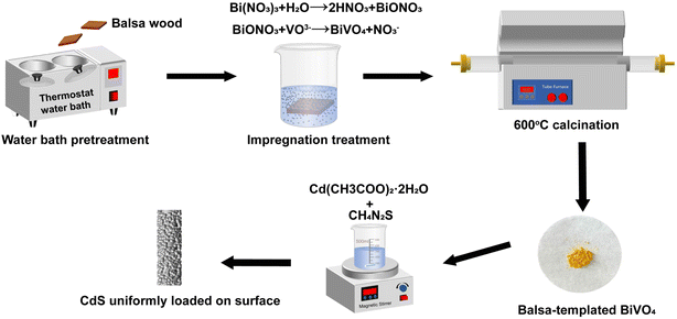
A large quantity of wastewater is released from wood processing, posing a serious pollution problem to the natural environment. Photocatalysis has become a reliable method for effluent purification. In this paper, balsa-templated BiVO4–CdS (BBC) was synthesized by impregnation calcination and chemical deposition using wood residue as a template. Rhodamine B (RhB) is used as a wood colorant and is present in wood processing wastewater. The performance of BBC in photocatalytic degradation with simultaneous hydrogen production was identified using RhB as simulated wood dye wastewater and a sacrificial electron donor. Compared to the BiVO4–CdS without a template, the BBC exhibited higher photocatalytic degradation performance (98.32%), which was attributed to the laminar porous structure of the wood being replicated. Because of the existence of a porous structure, BBC has better adsorption properties, which accelerated photodegradation and the production process of H2. Furthermore, surface modification with CdS nanoparticles formed Z-scheme heterojunctions, which greatly inhibited the photogenerated electron–hole compounds. When RhB provided electrons to BiVO4 and CdS, it was also removed by the oxidation of h+ and ·OH, which were simultaneously generated by balsa-templated BiVO4–CdS. BBC produced hydrogen at a higher rate (61.2 μmol g−1 h−1), realizing dual-functional photocatalysis. Therefore, the results support further development of dual-functional catalysts by the use of wood residues.
1. Introduction
Recently, water contamination and wasting of resources have become two main obstacles to global development. In wood processing and production, large amounts of wood processing residues and wood processing effluent are generated, causing serious waste of resources and water pollution.1 As a wood coloring agent Rhodamine B (RhB) is widely applied when dyeing wood and producing paper.2,3 RhB in wood dye wastewater can seriously irritate the nasal mucosa, eyes, and skin in humans if not treated in time.4 Compare to some conventional effluent remediation methods like physical adsorption and membrane filtration treatment, photocatalytic technology exhibits higher efficiency.5 At the same time, photocatalysis can also be used to decompose water for hydrogen production.6 Therefore, if effluent remediation and the production of H2 could be accomplished synergistically, the economic benefits would be greatly enhanced.7,8 Thus, wood dye wastewater is not only waste pollution but also an available resource.Currently, BiVO4 has become an important material in photocatalytic remediation of the environment due to its narrow bandgap and strong visible light response.9 However, its practical application in photocatalytic treatment is limited by its poor adsorption performance and the tendency of photoexcited carriers to compound.10,11 CdS is widely used as a hybrid element for semiconductor compounding.12,13 However, the coupling of the two still suffers from the lack of capacity to adsorb for pollutant molecules.14
Plenty of reports declare that different micromorphologies affect the adsorption properties of BiVO4.15 For example, BiVO4 artificial leaves that replicate the unique leaf-like morphology16 and corn straw templates of BiVO4 (ref. 17) exhibited stronger adsorption capacity than that of pure BiVO4. Inheriting the microstructure of natural materials is a way to modify the micromorphology of photocatalytic materials. However, high costs and complicated processes limit the majority template catalysts out of the laboratory and applied in large-scale practical production. Therefore, in a practical production sense, it is considerable to design and search for economical and sustainable materials as templates. In the natural world, wood is abundant and has a complex and regular layered porous structure, including nanoscale molecular fibres, micron-scale transverse rays, and millimetre-scale ductal pores. These factors make wood a good photocatalytic biomimetic template.18–20 However, plenty of wood processing residues are generated in the production and processing every year, with sawmill residues ranging from 35 to 45% depending on moisture content, wood species, log size, and production equipment; fibreboard or oriented strandboard production accounts for 4–12% of wood processing residues, with edge trimming of plywood and splicing of blockboard resulting in an increase of wood processing residues (45%); and approximately 40–50% of the input wood material can be recovered as useable fibre in the pulp manufacturing process.21,22 Hence, by using wood processing residues as a template to prepare photocatalysts for treating wood dyeing wastewater, the waste of valuable wood resources will be reduced.
In this study, a BiVO4–CdS catalyst with a balsa wood was obtained by impregnation-calcination and chemical deposition. The dual-functional of balsa-templated BiVO4–CdS were investigated through the removal and synergistic H2 production of RhB. Finally, the photogenerated electron–holes migration mode and principle of photocatalysis in balsa-templated BiVO4–CdS were clarified by trapping experiments and energy band analysis. This work provides a promising approach for the development of dual-functional biomass-templated photocatalysts.
2. Materials and methods
2.1 Materials
Bi(NO3)3·5H2O, NH4VO3, tetramethylammonium hydroxide aqueous solution (TMAH 25%), thiourea (CH4N2S), and Cd(CH3COO)2·2H2O were all purchased from McLean Reagent Co. Glycerin (C3H8O3); anhydrous ethanol (C2H5OH), deionized water with a conductivity of 0.055 μS cm−1, and nitric acid (65%) were all purchased from Tianjin Fuyu Fine Chemical Co. RhB (C28H31ClN2O3) was purchased from Fuchen (Tianjin) Chemical Reagent Co. All of the reagents were analytical grade and used without further purification. All balsa wood samples were 20 mm × 20 mm × 2 mm in size, and the balsa wood with an air-dry density of 0.14 g cm−3 was from the training and practice base for undergraduate innovation at Northeast Forestry University.2.2 Synthesis of the different photocatalysts
![[thin space (1/6-em)]](https://www.rsc.org/images/entities/char_2009.gif) :
:![[thin space (1/6-em)]](https://www.rsc.org/images/entities/char_2009.gif) 1, 1
1, 1![[thin space (1/6-em)]](https://www.rsc.org/images/entities/char_2009.gif) :
:![[thin space (1/6-em)]](https://www.rsc.org/images/entities/char_2009.gif) 1, 1
1, 1![[thin space (1/6-em)]](https://www.rsc.org/images/entities/char_2009.gif) :
:![[thin space (1/6-em)]](https://www.rsc.org/images/entities/char_2009.gif) 2 and 1
2 and 1![[thin space (1/6-em)]](https://www.rsc.org/images/entities/char_2009.gif) :
:![[thin space (1/6-em)]](https://www.rsc.org/images/entities/char_2009.gif) 4, and the prepared catalysts were marked as BBC-1, BBC-2, BBC-3, and BBC-4, respectively.
4, and the prepared catalysts were marked as BBC-1, BBC-2, BBC-3, and BBC-4, respectively.
To set up control samples, BiVO4, CdS, and BiVO4–CdS (1![[thin space (1/6-em)]](https://www.rsc.org/images/entities/char_2009.gif) :
:![[thin space (1/6-em)]](https://www.rsc.org/images/entities/char_2009.gif) 2) (without template) were prepared. The BiVO4 precursor solution (as described in Section 2.2.1) was dried at 80 °C for 48 h in a drying oven. Then solid residues were calcined at 600 °C for 6 h. BiVO4 was successfully obtained. Cd(CH3COO)2·2H2O (1 mmol) was dissolved in 50 ml of deionized water. Then 10 ml of 0.1 mol L−1 CH4N2S was dipped into the above liquid with vigorous stirring for 20 min. After the mixture was heated at 90 °C for 2.5 h and placed in a dark location for 24 h, the obtained samples were collected by centrifugation and rinsed with anhydrous ethanol and deionized water, then dried at 70 °C for 12 h. CdS was successfully obtained. BiVO4–CdS (1
2) (without template) were prepared. The BiVO4 precursor solution (as described in Section 2.2.1) was dried at 80 °C for 48 h in a drying oven. Then solid residues were calcined at 600 °C for 6 h. BiVO4 was successfully obtained. Cd(CH3COO)2·2H2O (1 mmol) was dissolved in 50 ml of deionized water. Then 10 ml of 0.1 mol L−1 CH4N2S was dipped into the above liquid with vigorous stirring for 20 min. After the mixture was heated at 90 °C for 2.5 h and placed in a dark location for 24 h, the obtained samples were collected by centrifugation and rinsed with anhydrous ethanol and deionized water, then dried at 70 °C for 12 h. CdS was successfully obtained. BiVO4–CdS (1![[thin space (1/6-em)]](https://www.rsc.org/images/entities/char_2009.gif) :
:![[thin space (1/6-em)]](https://www.rsc.org/images/entities/char_2009.gif) 2) (without template) was labeled as BC.
2) (without template) was labeled as BC.
2.3 Characterization
The crystallographic phase of all samples was proofed by a multifunctional powder X-ray diffractometer (XRD, X'Pert3Powder, Netherlands) with the following test conditions: Cu as the target radiation source (λ = 0.15406 nm), 40 kV, 40 mA, and scanning angle of 5–90°. Microstructure and morphology of all samples were recorded using field emission scanning electron microscopy (FESEM, JSM-7500F, Japan, acceleration voltage: 5 kV) and transmission electron microscopy (TEM, JEM-2100, Japan, acceleration voltage: 200 kV). Elemental composition and distribution on the sample surface were determined by Energy Dispersive Spectroscopy (EDS). The light absorption wavelengths of all samples were determined by UV-vis spectrophotometer (Agilent Cary100). The N2 adsorption–desorption isotherms of the prepared samples were tested using a fully automated specific surface area and porosity analyzer (Micromeritics ASAP 2460, USA). Photoluminescence (PL) spectra of the sample were tested on a steady-state/transient fluorescence spectrometer (FLS1000, Edinburgh Instruments). The transient current response spectra (I–T) and electrochemical impedance spectra (EIS) were measured on an electrochemical workstation (CHI 760E) using a standard three-chamber electrode with a Pt electrode as a counter electrode, Ag/AgCl as a reference electrode, and ITO as a working electrode. Aqueous 0.5 M Na2SO4 solution was selected as the electrolyte and the frequency range was 0.1 Hz to 100 kHz.2.4 Photocatalytic activity measurements
All photocatalytic hydrogen production tests were carried out in a Pyrex glass reaction cell connected to a closed gas-circulation and evacuation system (Perfect Light, Beijing, Labsolar-6A). Thirty milligrams of catalyst was dispersed in fifty milliliters of aqueous RhB solution with different concentrations, and then different loadings of Pt were loaded onto the catalyst surface by photodeposition of H2PtCl6. Before irradiation, the suspensions were left in the dark for 1 h to reach adsorption resolution equilibrium. Five millilitres of the solution was extracted using a 0.22 μm filter membrane and the supernatant was centrifuged to calculate the removal rate of RhB using a UV-visible spectrophotometer (UV-1000, Shanghai) to compare the adsorption capacity of each catalyst. The suspensions were then ventilated several times with Ar and irradiated with a 300 W Xe-lamp (PLS-SXE300+). A cut-off filter was used to simulate visible light (λ > 420 nm) irradiation. Hydrogen production was analyzed using an online gas chromatograph (GC9790II) with a thermal conductivity detector (TCD). Finally, at the end of the reaction, the degradation rate of RhB was calculated by the spectrophotometric method. The cyclic experiments were completed by four consecutive photocatalytic reactions. The amount of scavenger used in the trapping experiments was 1 mM.3. Results and discussion
3.1 Characterization of balsa-templated BiVO4–CdS
The crystalline phases of the as-prepared photocatalysts were initially identified by XRD. The XRD pattern of pure BiVO4 was identified to be compatible with the monoclinic scheelite (JCPDS No. 14-0688).23,24 The XRD result of CdS indicated the presence of the hexagonal phase (JCPDS No. 77-2306).25 The XRD pattern of BBC was similar to that of BC, which indicated that the balsa template does not affect the crystalline phase of the BiVO4–CdS heterojunction (Fig. 2). As the loading of CdS increases, the intensity of the characteristic peak of the hexagonal phase steadily increases (2θ = 25–28°), indicating that CdS was successfully loaded on BiVO4. These results clarified that the BBC catalyst was successfully prepared.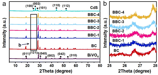 | ||
| Fig. 2 (a) XRD patterns of the prepared catalysts and (b) XRD patterns of BC, BBC-1, BBC-2, BBC-3, and BBC-4 with 2θ of 25–28°. | ||
The chemical binding conditions of BiVO4 and CdS can be identified by XPS. The XPS spectrum of BBC (Fig. 3a) shows that Cd, S, Bi, V, and O are the main elements of BBC. Bi3+ in BiVO4 (Fig. 3b) is observed with two high peaks at 158.58 eV (Bi 4f 7/2) and 163.88 eV (Bi 4f 5/2).26 Compared to both, the XPS peaks of Bi 4f in BBC are shifted to 158.28 eV and 163.48 eV. The XPS signal of O 1s in BiVO4 (Fig. 3d) is found at characteristic peaks of 529.28 eV and 531.38 eV. The binding energies of O 1s in BBC are shifted to 529.18 eV and 531.58 eV, respectively, which represent lattice oxygen and surface-adsorbed oxygen.27 After replicating the microstructure of balsa wood, the adsorption capacity of BBC on dissolved oxygen was greatly improved, which was reflected in the peak intensity of BBC increased at 531.58 eV. The positions of the characteristic peaks of Bi, V, and O demonstrate the successful synthesis of the monoclinic BiVO4. The peaks of Cd2+ in CdS (Fig. 3e) are 404.98 eV and 411.68 eV (Cd 3d 5/2). The Cd 3d in BBC shifts to 404.78 eV and 411.48 eV, respectively.28 The XPS pattern of Cd and S indicate that hexagonal CdS was uniformly loaded on the BiVO4 surface.29 Additionally, the positive shift of the characteristic peaks of V 2p (Fig. 3c) in BBC and the shift of the characteristic peaks of Bi 4f, S 2p, and Cd 3d to lower energies indicate the effective chemical interaction and good binding between BiVO4 and CdS,30,31 which is consistent with the XRD results.
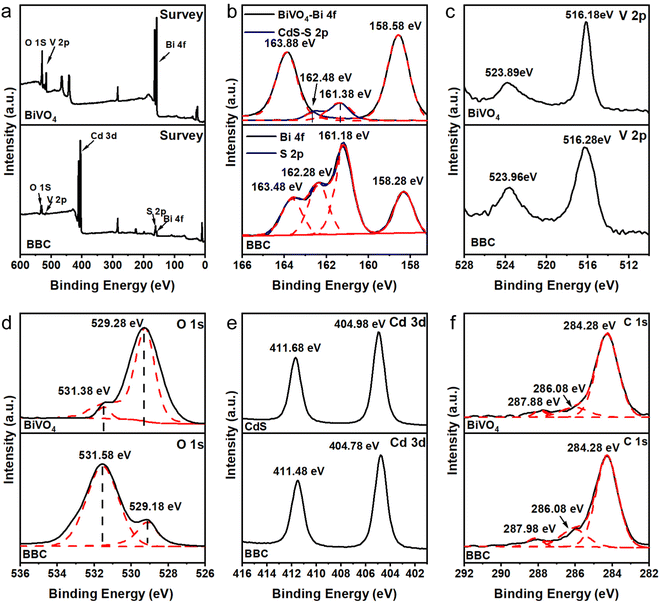 | ||
| Fig. 3 Survey XPS spectra (a) and high-resolution XPS spectra of Bi 4f, S 2p (b), V 2p (c), O 1s (d), Cd 3d (e) and C 1s (f). | ||
The inheriting of wood microstructure in BiVO4 was studied by SEM. By replicating the microscopic morphology of the wood (Fig. 4b and c), BiVO4–CdS changed from the original irregular arrangement (Fig. 4a) to a tubular organization with a diameter of approximately 7–15 μm, growing along the longitudinal wood ray cavities of the wood. When balsa wood samples were impregnated in BiVO4 precursor solution, plenty of the solution entered the wood cells and occupied the space along the wood ray channels (Fig. S1†); thus, most of the internal structure of the wood was preserved after calcination. In addition, CdS nanoparticles are uniformly bound to the surface of BiVO4 by the high magnification SEM images. The EDS data (Fig. 4e) demonstrates the presence of Bi, V, O, Cd, and S elements in BBC, while CdS is modified on BiVO4, which is consistent with the XPS results. The HRTEM image of BBC (Fig. 4d) shows that the lattice spacing of 0.31 nm corresponds to the (121) crystal plane of monoclinic phase BiVO4,32 while the lattice spacing of 0.32 nm corresponds to the (101) crystal plane of the hexagonal phase CdS. The TEM results further confirm the good binding of BiVO4 and CdS.29
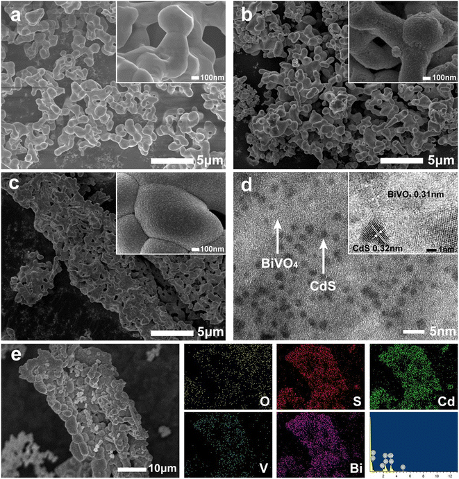 | ||
| Fig. 4 SEM images of BiVO4 (a), BC (b), and BBC-3 (c); TEM image and HRTEM image of BBC-3 (d); EDS pattern and elemental mapping of BBC-3 (e). | ||
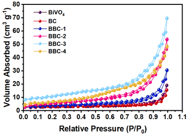
The pore condition of the photocatalysts was further analyzed by N2 adsorption–desorption experiment (Fig. 5). The calculated specific surface areas of BiVO4, BC, BBC-1, BBC-2, BBC-3, and BBC-4 were 6.48, 7.11, 12.33, 20.48, 28.09, and 21.76 m2 g−1, respectively. The SEM images show that the catalyst surface is covered with small nanoscale pores (10–20 nm) and other slit-type pore channels are formed due to the accumulation of agglomerates on each other. Generally, when the specific surface area of the material is large, plenty of pollutant molecules are easily absorbed by the material. The rapid contact between pollutants and photogenerated strong oxidizing substances speeds the photocatalytic progress.33,34
The light absorption band gap variation was analyzed by DRS. All catalysts have good absorption of the visible light (Fig. 6a). The absorption wavelengths of the composite catalysts all lie between the BiVO4 (510 nm) and CdS (584 nm) (Table S1†).
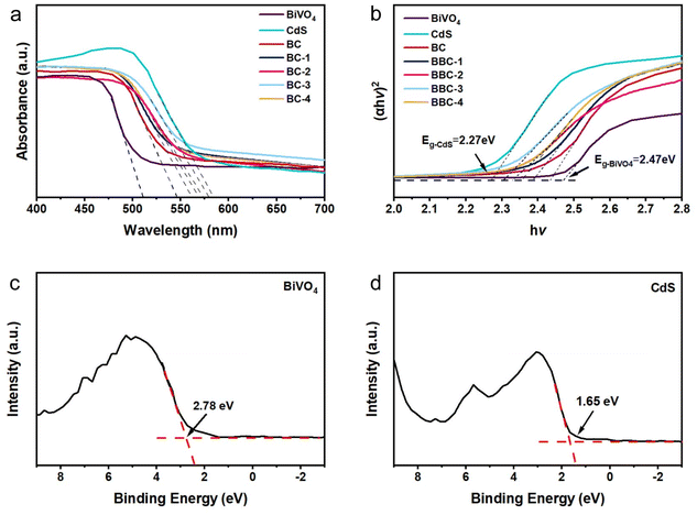 | ||
| Fig. 6 (a) UV-vis DRS of the prepared catalysts and (b) the corresponding (αhν)2 vs. hν plots. Valence-band XPS spectrum of BiVO4 (c) and CdS (d). | ||
At the same time, all the composite catalysts produce different degrees of redshift compared with that of BiVO4, in which BBC-3 exhibited the largest absorption expansion. Because of the interfacial interaction between BiVO4 and CdS, the absorbing light range of the catalyst expands. At the same time, BBC exhibits the porous structure of wood, and it can transmit sufficient light and obtain a large range of light absorption, which enhances the light responsiveness. Normally, the wider the optical absorption wavelength, the stronger the photoresponse. The forbidden bandgap of the semiconductor can be estimated by eqn (1) as follows:
| (αhν)1/n = A(hν − Eg) | (1) |
3.2 Adsorption performance of the balsa-templated BiVO4–CdS
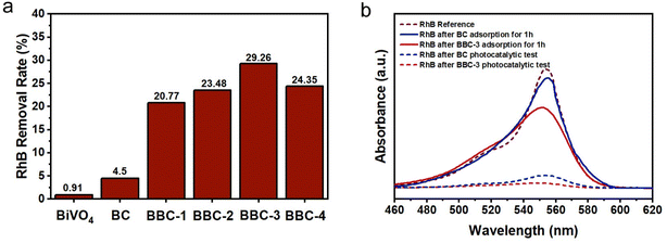
After replicating the microstructure of the wood, the adsorption performance of BBC was greatly enhanced (Fig. 7a). When the adsorption resolution equilibrium was reached, the removal rate of RhB by BBC-3 was 29.26%, which was 6.5 times higher than the removal rate of BC (4.5%). It can also be seen that the concentration of RhB decreased significantly after 1 h of adsorption by BBC-3 (Fig. 7b). The adsorption efficiency of BBC was compared with that of other reported BiVO4–CdS materials with different structures (Table 1). Compared to using conventional structure, using wood as a template is more advantageous in terms of adsorption. In general, the steps of semiconductor photocatalytic reactions involve the excitation of photocatalytic materials by photons with energy higher than their forbidden bandgap to produce photoexcited carriers. Then the pollution molecule adsorbed on the material surface was oxidated and reduced by these carriers.37 If the catalyst exhibits a good adsorption capacity, then the subsequent photocatalytic reaction process will speed up (Fig. 8).| Photocatalyst | Solution | Removal efficiency (adsorption equilibrium) | Reference |
|---|---|---|---|
| Balsa templated-BiVO4–CdS | 10 mg per L RhB | 29.26% | This work |
| Hollow CdS/BiVO4 | 15 mg per L RhB | 0.536% | 38 |
| BiVO4–CdS | 20 mg per L TCH | 1.435% | 14 |
| SDBC–BiVO4–CdS | 20 mg per L TCH | 3.138% | 14 |
| PVP–BiVO4–CdS | 20 mg per L TCH | 6.384% | 14 |
| EDTA–BiVO4–CdS | 20 mg per L TCH | 9.221% | 14 |
| BiVO4–Au@CdS | 5 mg per L RhB | 9.248% | 39 |
| Hierarchical construction Bi/BiVO4–CdS | 20 mg per L TCH | 20.865% | 40 |
3.3 Photocatalytic performance of the balsa-templated BiVO4–CdS
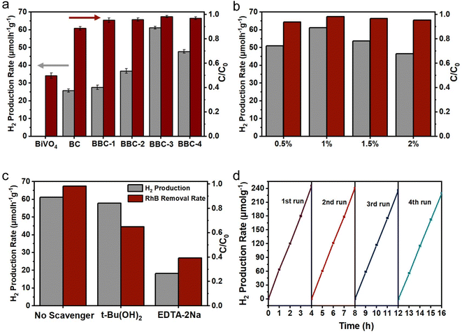
To verify the photocatalytic performance of the BBC, tests on photocatalytic H2 production and simultaneous degradation of RhB were carried out. The rate of H2 production and RhB removal increased rapidly with increasing CdS content (Fig. 8a), and the rate of H2 production and RhB degradation reached a maximum (61.2 μmol g−1 h−1) when BiVO4![[thin space (1/6-em)]](https://www.rsc.org/images/entities/char_2009.gif) :
:![[thin space (1/6-em)]](https://www.rsc.org/images/entities/char_2009.gif) CdS was 1
CdS was 1![[thin space (1/6-em)]](https://www.rsc.org/images/entities/char_2009.gif) :
:![[thin space (1/6-em)]](https://www.rsc.org/images/entities/char_2009.gif) 2. The rate of H2 production significantly decreased when the loading amount of CdS continued to increase. This occurred because the CdS loading on BiVO4 forms a heterogeneous structure, which greatly inhibits the compounding of photoexcited carriers and improves the electron–hole separation efficiency. However, when the loading amount of CdS reaches a certain level, a portion of the active site is covered, which affects the photoresponse ability of the BBC under visible light. Therefore, when the BiVO4
2. The rate of H2 production significantly decreased when the loading amount of CdS continued to increase. This occurred because the CdS loading on BiVO4 forms a heterogeneous structure, which greatly inhibits the compounding of photoexcited carriers and improves the electron–hole separation efficiency. However, when the loading amount of CdS reaches a certain level, a portion of the active site is covered, which affects the photoresponse ability of the BBC under visible light. Therefore, when the BiVO4![[thin space (1/6-em)]](https://www.rsc.org/images/entities/char_2009.gif) :
:![[thin space (1/6-em)]](https://www.rsc.org/images/entities/char_2009.gif) CdS ratio is 1
CdS ratio is 1![[thin space (1/6-em)]](https://www.rsc.org/images/entities/char_2009.gif) :
:![[thin space (1/6-em)]](https://www.rsc.org/images/entities/char_2009.gif) 2, a better amount of CdS is loaded in the composite.
2, a better amount of CdS is loaded in the composite.
Then, the effects of different loading amounts of Pt on the H2 production and RhB degradation efficiency were investigated using BBC-3. As shown in Fig. 8b, the rate of H2 production and RhB degradation increased as the Pt loading increased from 0.5% to 1%, while the rate of H2 production and RhB removal decreased a little as the Pt loading increased from 1% to 2%. This situation occurs because Pt clusters form on the surface of BBC-3 when the loading amount of Pt exceeds 1%, which reduces the availability of this part of Pt; as a result, the efficiency of photogenerated electron–hole separation decreases and the photocatalytic ability of the catalyst weakens.41,42
In addition, the effect of the initial concentration of RhB solution on the photocatalytic H2 generation of BBC-3 was further studied. As the initial concentration of RhB solution increased, the rate of H2 generation increased first and then decreased. The fastest rate of H2 production was achieved at an initial RhB concentration of 10 mg L−1 (Fig. S2a†). When the dye concentration initially increases, more RhB molecules adsorb to the catalyst surface, which in turn can interact with the photogenerated electron holes more rapidly. As the RhB concentration further increases, the irradiation of some visible light through the water bodies to BBC-3 is hindered, leading to a lower rate of H2 production.43 Finally, the long-term stability of BBC-3 was examined by four rounds of cycling experiments (Fig. 8d). After four consecutive cycles (Fig. S2b†), the rate of H2 generation decreased slightly (61.2 → 57.31 μmol g−1 h−1), and the rate of synergistic degradation of RhB remained almost unchanged (98.33 → 95.27%). The results indicate that BBC-3 exhibits excellent long-term stability and photocatalytic activity.
The photogenerated electron–hole complexation rate is a key factor that affects the photocatalytic performance of photocatalysts. The photogenerated electron–hole separation of the prepared catalysts was investigated by fluorescence spectra, photocurrent response, and EIS spectra. Fig. 9a shows the PL spectra of BiVO4, CdS, BC, and BBC-3. Compared with BiVO4 and CdS, both BC and BBC-3 exhibit a significantly weaker fluorescence intensity, and the fluorescence intensity of BBC-3 is the weakest, indicating that photogenerated electron–hole complexation is inhibited in the presence of heterojunctions, and the electron–hole on BBC-3 exhibits the best separation efficiency.44 Photoelectrochemical experiments were then performed, the photocurrent response of BBC-3 is much higher than those of BiVO4, CdS, and BC (Fig. 9b), which indicates that photogenerated electron–holes are more readily transferred to the surface for redox reactions through the channels formed by the wood template, which is consistent with the photoluminescence results.45 EIS spectra were used to elucidate the migration of photoexcited electron–holes. In the Nyquist plot, the arc radius represents the equivalent resistance, and the larger the arc radius, the higher the recombination of the photoexcited electron–hole.46 The semicircular radius of BBC-3 is smaller than those of BiVO4, CdS, and BC (Fig. 9c), thus indicating that BBC-3 shows a higher migration efficiency for photogenerated carriers.
To clarify the principle of synergistic H2 production from RhB photodegradation, trapping experiments were performed to investigate the main active species in the photocatalytic process on BBC-3. Hydroxyl radical (·OH) and hole (h+) trapping experiments were performed by adding t-Bu(OH)2 and EDTA-2Na, respectively. When adding t-Bu(OH)2 to the system, the degradation rate of RhB was somewhat affected, and it was hardly affected by the efficiency of H2 production. When EDTA-2Na was present in the system, the rate of H2 production and the removal rate of RhB decreased greatly. The results of the active species trapping indicated that both h+ and ·OH were involved in the RhB degradation process, while ·OH was basically not involved in the photocatalytic H2 production process, and h+ is the main active substances for photocatalytic degradation and photocatalytic H2 production. These results further demonstrate that RhB acts as a sacrificial electron donor and scavenges photogenerated holes to promote H2 production while leading to its own decomposition (Fig. S2c†).
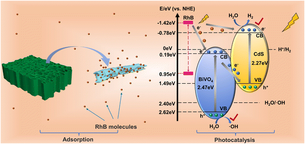
The results of photodegradation of RhB with simultaneous production of H2 illustrated that the complexation of CdS improved the photoresponsiveness of BiVO4 and that the replication of wood micromorphology exhibited a better adsorption ability. To elucidate the photocatalytic mechanism of this system, the empirical equation Eg = EVB − ECB was used to calculate the conduction band (CB) potentials of pure BiVO4 and CdS.47 According to the calculated EVB of BiVO4 and CdS, it is calculated that ECB-BiVO4 = 0.15 eV and ECB-CdS = −0.78 eV (vs. NHE). Apparently, when BiVO4 and CdS are hybridized, suitable band structures can be established to improve the electron–hole pair efficiency.
In addition, the RhB molecules adsorbed on the catalyst surface can generate electrons by photoexcitation, and the LUMO and HOMO of RhB are −1.42 and 0.95 eV, respectively.48,49 Since the LUMO site of RhB is more negative than the CB of BiVO4 and CdS, photogenerated electrons can be delivered to BiVO4 and CdS. In this way, the large amount of foreign electrons that are injected increases the carrier migration rate between the catalyst interfaces, which in turn enhances the photocatalytic efficiency. The carrier transfer mode is discussed below.
If the electron transfer between BiVO4 and CdS follows the traditional type II heterojunction, then the photogenerated electrons will transfer from the CB of CdS to the CB of BiVO4, and the photogenerated holes will transfer from the VB of BiVO4 to CdS. At this time, the electrons and holes will accumulate at the CB of BiVO4 and the VB of CdS, respectively. Since the reduction potential of H2 is more negative than the CB of BiVO4, and the oxidation potential of ·OH is more positive than the VB of CdS, then H2 and ·OH cannot be produced, which is inconsistent with the experimental results. Therefore, the transfer of carriers should follow a more reasonable mechanism, the Z-scheme transfer mechanism.
The irregular BiVO4–CdS agglomerates improve the transfer efficiency of photocatalytic products and RhB molecules at the interface due to the three-dimensional pore structure of wood.50,51 The BBC rapidly adsorbs a large number of RhB molecules, and subsequently, the RhB molecules are excited by light and generate electrons that are inputted onto the CB of BiVO4 and CdS. In the heterojunction of BiVO4–CdS, the electrons in the CB of BiVO4 can be rapidly moved to the VB of CdS to regroup with the photogenerated holes it produces. At this point, the photogenerated holes of BiVO4 and the photogenerated electrons of CdS are retained. The holes in the VB of BiVO4 and the electrons in the CB of CdS produce ·OH and H2 during photoexcitation, which is consistent with the photocatalytic results (Fig. 10). RhB was removed by its own supply of electrons while being oxidized by ·OH. Through this photogenerated carrier transfer mode, the composite BiVO4–CdS exhibits better redox performance to degrade pollutants while generating hydrogen, making BBC-3 a good dual-functional catalyst.
4. Conclusions
Balsa-templated BiVO4–CdS was successfully synthesized by impregnation calcination and chemical deposition methods. The two processes, photocatalytic dye degradation and hydrogen production, were integrated into a single system. Compared with the untemplated BiVO4–CdS (4.5%), the balsa-templated BiVO4–CdS exhibited an extremely high adsorption capacity (29.26%). Additionally, BiVO4 and CdS formed Z-scheme heterojunctions, thus exhibiting superior photocatalytic hydrogen production and degradation performance. The balsa-templated BiVO4–CdS produced H2 at a higher rate (61.2 μmol g−1 h−1), while the RhB removal rate (98.32%) was higher under visible light. To the best of our knowledge, few reports have investigated biomass template dual-functional catalytic systems. At the same time, resources are sustainably recycled by using wood residues as the template. In addition, synergistic hydrogen production for the degradation of other dyes will be further investigated in future work. This study contributes to the goal of developing novel dual-functional catalysts that offer a new possibility for water remediation and energy development.Author contributions
Guangda Xia: investigation, resources, validation, data curation, formal analysis, writing – original draft, visualization. Sichen Xiao: investigation, resources, validation, data curation. Junjie Su: investigation, supervision, software, formal analysis, visualization. Hui Zhou: methodology, supervision. Yu Liu: conceptualization, methodology, validation, formal analysis, writing – review & editing, visualization, supervision, project administration, funding acquisition. Xiaodong Zhu: conceptualization, methodology, writing − review & editing, supervision.Conflicts of interest
The authors declare that they have no known competing financial interests or personal relationships that could have appeared to influence the work reported in this paper.Acknowledgements
This work is financially supported by National Natural Science Foundation of China (Grant 32201481), Fundamental Research Funds for the Central Universities (2572022BB07), Innovative Entrepreneurial Projects for College Students (202210225092).References
- A. Vlyssides, E. M. Barampouti, S. Mai and A. Vlyssides, Environ. Eng. Sci., 2008, 25, 327–332 CrossRef CAS.
- T. H. Yen Doan, T. P. Minh Chu, T. D. Dinh, T. H. Nguyen, T. C. Tu Vo, N. M. Nguyen, B. H. Nguyen, T. A. Nguyen and T. D. Pham, J. Anal. Methods Chem., 2020, 2020, 6676320 Search PubMed.
- E. García-López, A. Alcázar, A. M. Moreno and C. Cid, Color-Producing Extremophiles, Bio-Pigm. Biotechnol. Implementations, 2017, 3, 61–86 Search PubMed.
- M. S. Field, R. G. Wilhelm, J. F. Quinlan and T. J. Aley, Environ. Monit. Assess., 1995, 38, 75–96 CrossRef CAS PubMed.
- G. Chandrabose, A. Dey, S. S. Gaur, S. Pitchaimuthu, H. Jagadeesan, N. Braithwaite, V. Selvaraj, V. Kumar and S. Krishnamurthy, Chemosphere, 2021, 279, 130467 CrossRef CAS PubMed.
- J. W. Hong, Catalysts, 2021, 11, 848 CrossRef CAS.
- Z. D. Wei, M. Q. Xu, J. Y. Liu, W. Q. Guo, Z. Jiang and W. F. Shangguan, Chin. J. Catal., 2020, 41, 103–113 CrossRef CAS.
- H. Wang, Y. Wu, M. Feng, W. Tu, T. Xiao, T. Xiong, H. Ang, X. Yuan and J. W. Chew, Water Res., 2018, 144, 215–225 CrossRef CAS PubMed.
- I. Grigioni, G. Di Liberto, M. V. Dozzi, S. Tosoni, G. Pacchioni and E. Selli, ACS Appl. Energy Mater., 2021, 4, 8421–8431 CrossRef CAS PubMed.
- Y. Zhang, J. Q. Yu, A. Kudo and X. S. Zhao, Chin. J. Catal., 2008, 29, 624–628 CrossRef CAS.
- M. N. Guo, Y. Wang, Q. L. He, W. J. Wang, W. M. Wang, Z. Y. Fu and H. Wang, RSC Adv., 2015, 5, 58633–58639 RSC.
- L. Zou, X. Wang, X. Xu and H. Wang, Ceram. Int., 2016, 42, 372–378 CrossRef CAS.
- M. Zhukovskyi, P. Tongying, H. Yashan, Y. Wang and M. Kuno, ACS Catal., 2015, 5, 6615–6623 CrossRef CAS.
- Z. Wu, Y. Xue, X. He, Y. Li, X. Yang, Z. Wu and G. Cravotto, J. Hazard. Mater., 2020, 387, 122019 CrossRef CAS PubMed.
- Y. Lu, H. Shang, F. Shi, C. Chao, X. Zhang and B. Zhang, J. Phys. Chem. Solids, 2015, 85, 44–50 CrossRef CAS.
- R. Yang, R. Zhu, Y. Fan, L. Hu and Q. Chen, RSC Adv., 2019, 9, 14004–14010 RSC.
- M. Wang, H. Zheng, J. Liu, D. Dong, Y. Che and C. Yang, Mater. Sci. Semicond. Process., 2015, 30, 307–313 CrossRef CAS.
- Z. Liu, T. Fan, J. Gu, D. Zhang, X. Gong, Q. Gu and J. Xu, Mater. Trans., 2007, 48, 878–881 CrossRef CAS.
- Z. Liu, T. Fan, W. Zhang and D. Zhang, Microporous Mesoporous Mater., 2005, 85, 82–88 CrossRef CAS.
- T. Yang, Y. Liu, G. Xia, X. Zhu and Y. Zhao, J. Cleaner Prod., 2021, 329, 129726 CrossRef CAS.
- U. Saal, H. Weimar and U. Mantau, in Biorefineries, ed. K. Wagemann and N. Tippkotter, 2019, vol. 166, pp. 27–41 Search PubMed.
- G. Faraca, A. Boldrin and T. Astrup, Waste Manag., 2019, 87, 135–147 CrossRef CAS PubMed.
- L. Zhang, D. Chen and X. Jiao, J. Phys. Chem. B, 2006, 110, 2668–2673 CrossRef CAS PubMed.
- H. Fan, D. Wang, Z. Liu, T. Xie and Y. Lin, Dalton Trans., 2015, 44, 11725–11731 RSC.
- D. Wang, L. Guo, F. Fu, Y. Liang and H. Shen, New J. Chem., 2016, 40, 8614–8624 RSC.
- F. Fang, Y. Zhang, J. Bai, J. Li, X. Mei, C. Zhou, M. Zhou and B. Zhou, Environ. Pollut., 2020, 267, 115605 CrossRef CAS PubMed.
- P. G. Ingole, H. Y. Sang, P. G. Ingole, W. K. Choi and H. K. Lee, J. Mater. Chem. A, 2015, 3, 7888–7899 RSC.
- Z. Yu, Y. Xie, G. Liu, G. Lu, X. Ma and H. Cheng, J. Mater. Chem. A, 2013, 1, 2773–2776 RSC.
- L. J. Zhang, S. Li, B. K. Liu, D. J. Wang and T. F. Xie, ACS Catal., 2014, 4, 3724–3729 CrossRef CAS.
- Y. Zhang, Y. Guo, H. Duan, L. Hua and H. Liu, Phys. Chem. Chem. Phys., 2014, 16, 24519–24526 RSC.
- S. Bao, Q. Wu, S. Chang, B. Tian and J. Zhang, Catal. Sci. Technol., 2016, 7, 124–132 RSC.
- X. Li, J. Sun, Q. Zhao, M. O. Tade and S. Liu, J. Mater. Chem. A, 2015, 3, 21655–21663 RSC.
- W. Zhou, Z. Yin, Y. Du, X. Huang, Z. Zeng, Z. Fan, H. Liu, J. Wang and H. Zhang, Small, 2013, 9, 140–147 CrossRef CAS PubMed.
- G. Yang, D. Chen, H. Ding, J. Feng, J. Zhang, Y. Zhu, S. Hamid and D. W. Bahnemann, Appl. Catal., B, 2017, 219, 611–618 CrossRef CAS.
- G. Zhang, D. Chen, N. Li, Q. Xu, H. Li and J. He, Appl. Catal., B, 2018, 232, 164–174 CrossRef CAS.
- Y. Xu and M. Schoonen, Am. Mineral., 2000, 85, 543–556 CrossRef CAS.
- A. L. Linsebigler, G. Lu and J. T. Yates, Chem. Rev., 1995, 95, 735–758 CrossRef CAS.
- Y. Lin, D. Pan and H. Luo, Mater. Sci. Semicond. Process., 2021, 121, 105453 CrossRef CAS.
- F. Ye, H. Li, H. Yu, S. Chen and X. Quan, Appl. Catal., B, 2018, 227, 258–265 CrossRef CAS.
- Y. Xue, Z. Chen, Z. Wu, F. Tian and B. Yu, Sep. Purif. Technol., 2021, 275, 119152 CrossRef CAS.
- Z. Lu, W. Song, O. Chao, H. Wang, D. Zeng and C. Xie, RSC Adv., 2017, 7, 33552–33557 RSC.
- F. Fina, H. Ménard and J. T. S. Irvine, Phys. Chem. Chem. Phys., 2015, 17, 13929–13936 RSC.
- S. Kampouri, T. N. Nguyen, M. Spodaryk, R. G. Palgrave, A. Züttel, B. Smit and K. C. Stylianou, Adv. Funct. Mater., 2018, 28, 1806368 CrossRef.
- X. Wu, J. Zhao, L. Wang, M. Han, M. Zhang, H. Wang, H. Huang, Y. Liu and Z. Kang, Appl. Catal., B, 2017, 206, 501–509 CrossRef CAS.
- W. Zhao, Z. Wei, G. Zhu, T. Lin and Q. H. Fu, Dalton Trans., 2016, 45, 3888–3894 RSC.
- X. Ding, Y. Wang, H. Shi, L. Huang, Y. Zuo and S. Kang, Appl. Surf. Sci., 2017, 391, 202–210 CrossRef.
- X. Chen, Y. Zhou, Q. Liu, Z. Li and J. Liu, ACS Appl. Mater. Interfaces, 2012, 4, 3372–3377 CrossRef CAS PubMed.
- Z. Chen, J. Zhao, J. Chen, Y. Zhang, D. Chen, Q. Wang and D. Xia, Sep. Purif. Technol., 2021, 258, 118007 CrossRef CAS.
- R. Bibi, Q. Shen, L. Wei, D. Hao, N. Li and J. Zhou, RSC Adv., 2018, 8, 2048–2058 RSC.
- D. R. Rolison, Science, 2003, 299, 1698–1702 CrossRef CAS PubMed.
- S. Dapurkar, S. Badamali and P. Selvam, Catal. Today, 2001, 68, 63–68 CrossRef CAS.
Footnote |
| † Electronic supplementary information (ESI) available. See DOI: https://doi.org/10.1039/d2ra06735h |
| This journal is © The Royal Society of Chemistry 2023 |

