
 Open Access Article
 This Open Access Article is licensed under a Creative Commons Attribution-Non Commercial 3.0 Unported Licence
Triboelectric behaviour of selected MOFs in contact with metals†
Andris Šutka *a,
Fa-Kuen Shieh*b,
Martynas Kinkac,
Linards Lapčinskisa,
Chien-Chun Changb,
Phuc Khanh Lamb,
Kaspars Pudzsd and
Osvalds Vernersa
*a,
Fa-Kuen Shieh*b,
Martynas Kinkac,
Linards Lapčinskisa,
Chien-Chun Changb,
Phuc Khanh Lamb,
Kaspars Pudzsd and
Osvalds Vernersa
aInstitute of Materials and Surface Engineering, Faculty of Materials Science and Applied Chemistry, Riga Technical University, Paula Valdena 3/7, Riga, 1048, Latvia. E-mail: Andris.Sutka@rtu.lv
bDepartment of Chemistry, National Central University, Taoyuan, 32001, Taiwan. E-mail: fshieh@ncu.edu.tw
cFaculty of Physics, Vilnius University, Sauletekio av. 3, Vilnius, 10257, Lithuania
dInstitute of Solid State Physics, University of Latvia, Kengaraga 8, Riga, 1063, Latvia
First published on 20th December 2022
Abstract
MOFs have been effectively used to magnify the triboelectric charge of polymers. However, so far the individual triboelectric properties and charge transfer mechanisms of MOFs haven't been reported. Triboelectric property investigation for selected MOFs show that the main mechanism for MOF triboelectrification in contact with metals is electron transfer.
Introduction
There is a strong interest to study the contact electrification (CE) properties of various materials to design triboelectric nanogenerator (TENG) devices with better efficiencies. TENG devices were introduced in 2012 as an alternative concept for converting waste mechanical energy into the electricity to power the autonomous microdevices thus reducing environmental burden from producing energy or using batteries.1,2 So far TENG devices have been shown to illuminate up to 8000 LEDs,3 driving autonomous gas sensor devices,4 powering biomedical devices5 and charging batteries.6Metal organic frameworks (MOFs) are crystalline compounds consisting of a 3D network formed by metal ion and an organic ligand.7 MOFs has been proposed for usage in a broad range of various applications such as energy storage,8 gas storage,9 catalysis,10 gas separation,11 etc. Recently, many MOFs including ZIF-8, ZIF-62, UiO-66-NH2, have been reported in applications of TENG devices.12–20 Guo et al. demonstrated that the fluorinated MOF can be used as a universal filler in composites for improving CE of different polymers such as polyvinylidene fluoride, polytetrafluorethylene, polydimethylsiloxane (PDMS), and polyurethane. Strong enhancement with 60 times higher electric current output from PDMS based TENG device was observed when adding MOF UiO-66-NH2.17 In other work, effective power 13 times higher was measured from PDMS composite containing Cu3(1,3,5-benzenetricarboxylate)2 MOF.18 MOFs has several advantages such as high surface area, porosity, and availability for chemical modification without changing the topology.14
So far MOFs have been used as a filler in polymer matrix to magnify the contact surface charge.15,17,18 The triboelectric properties of MOFs have been studied by contacting-separating with polymer films such as Kapton, ethyl-cellulose or Teflon.12–14,16 However, all these polymers exhibit strong CE by themselves.21,22 Individual CE properties of MOFs have not been reported. MOFs contain metallic and organic counterparts thus different CE mechanisms may coexist. Metallic counterparts of MOFs could be involved in electron transfer but heterolytic breakage of organic ligand may provide transfer of organoionic moieties.23 In addition, MOFs often contain the water adsorbates, which may provide CE charge formation due to ion transfer.
In the present study we report the individual triboelectric properties of various MOFs – MOF-74, ZIF-8, UiO-66 and UiO-66-NH2. The selected MOFs already has been used in TENG devices,12–18 as well as can be synthesized by straightforward approaches with high purity. UiO-66-NH2 was selected to study the influence of –NH2 termination on triboelectric charging of UiO-66. We have designed our experiment so that the individual CE behaviour of MOFs can be revealed. The present study deepens the insight in MOF triboelectrification mechanisms for designing more effective TENG devices in future.
Experimental
The synthetic procedure of ZIF-8
ZIF-8 was synthesized according to method reported in literature.24 250.0 mg zinc nitrate hexahydrate (Zn(NO3)2·6H2O) was added into 7.5 mL deionized water (D.I. water) as solution A. Solution B containing 1725.0 mg 2-methylimidazole and 10.0 mg polyvinylpyrrolidone (PVP) in 7.5 mL D.I. water. Following, solution A was poured into solution B with sonication for 5 min. The as-synthesized products were collected by centrifugation (10![[thin space (1/6-em)]](https://www.rsc.org/images/entities/char_2009.gif) 000g) for 5 min, and then washed with excess D.I. water three times, and finally vacuum-dried at room temperature.
000g) for 5 min, and then washed with excess D.I. water three times, and finally vacuum-dried at room temperature.
The synthetic procedure of UiO-66
UiO-66 was synthesized according to method reported in literature.25 125.0 mg zirconium(IV) chloride was dissolved in the mixture of 1.0 mL concentrated hydrochloric acid (HCl) 12.0 M and 5.0 mL N,N-dimethylformamide (DMF) by sonication for 20 min. The obtained solution was added to 10.0 mL DMF which contains 123.0 mg terephthalic acid (H2BDC). After mixing, the solution was heated in an oil bath at 80 °C for 8 h. The as-synthesized products were collected by centrifugation (8800g) for 5 min, then washed with DMF two times, with ethanol three times, and finally vacuum-dried at room temperature.The synthesis procedure of UiO-66-NH2
UiO-66-NH2 was synthesized according to method reported in literature.26 268.0 mg ZrCl4 was dissolved in the mixture of 2.0 mL concentrated HCl 12.0 M and 20.0 mL DMF by sonication for 20 min. The obtained solution was added to 10.0 mL DMF which contains 250.0 mg 2-aminoterephthalic acid. The mixture was heated in an oil bath at 80 °C for 24 h. After cooling down to room temperature, yellow precipitating residues were collected by centrifugation (8800g) for 5 min, rinsed by DMF and methanol for three times respectively, and finally vacuum-dried at room temperature overnight.The synthesis procedure of Zn-MOF-74
Zn-MOF-74 was synthesized according to method reported in literature.27 1000.0 mg zinc nitrate hexahydrate Zn(NO3)2·6H2O and 250.0 mg 2,5-dihydroxyterephtalic acid (H4DOBDC) were dissolved in the mixture of 20 mL DMF and 2.5 mL D.I. water by sonication for 2 min. The obtained solution was heated in an oil bath at 100 °C for 22 h. After cooling down to room temperature, the precipitating residues were collected by centrifugation (3900g) for 5 min and then washed three times with DMF. The obtained materials were immersed in methanol for one day and then collected by centrifuge (3900g) for 5 min, and finally vacuum-dried at room temperature overnight.Material characterizations
Powder X-ray diffraction (PXRD) patterns were collected using a Bruker D2 PHASER. Scanning electron microscope (SEM) images were collected by a Jeol JSM-7000F field emission scanning electron microscope (FE-SEM). Surface roughness Ra was determined from surface scan of electrodes using atomic force microscope (Veeco CPII scanning probe microscope).Contact electrification studies
MOFs were deposited on insulative glass and contacted with various conductive electrodes – Al, Ni–Mo, Ti and Ag. Glass was chosen to support MOFs because it does not exhibit any significant surface charge when contacted with the conductive electrodes (ESI Fig. S1†). In previous studies on triboelectric properties of MOFs, they have been adhered to adhesive tape.12–14 The adhesive layer may provide very strong CE charge by itself,28 therefore insulative glass substrate was chosen.For deposition, the MOF powders in concentration of 25 mg mL−1 were dispersed in toluene using ultrasonication (Hielscher UP200St, 10 W mL−1). MOF suspensions were spin-coated on glass by dripping 350 μL of suspension on rotating substrate at 1200 rpm. Before deposition, the glass substrates were cleaned in air plasma (Harrick Plasma PDC-002, 30 W for 5 min). Three parallel samples were prepared for each measurement. After drying MOF samples were directed for CE measurements. The current generated upon contact-separation was measured under controlled conditions – a separation distance of 5 mm, a pressing force of 10 N, and a contact-separation frequency of 1 Hz. To ensure repeatability, contact-separation was carried out using an Instron E1000 material testing machine. The generated current signals were measured using Keithley 6514 electrometer connected to a Picoscope 5444B PC oscilloscope system. Surface charges, Q (nC), were calculated from the measured current peaks using the equation Q = ∫idt, where i is the instantaneous current (nA) and dt is the differential of time (s). The residual charge after contact-separation was determined by compressing MOF or polymer with electrode for 1 hour using approximately 10 N force. Afterwards, the contacted electrode was oscillated without contact against another electrode connected in Faraday cup measurement mode. The registered current signal was used to calculate the residual charge on the previously contacted electrode.
Numerical studies
The density functional theory (DFT) calculation of the work functions of MOFs were computed by means of the package Quantum ESPRESSO29,30 employing the pseudopotentials (see Table S1†). For determining the number of sampling points for reciprocal space calculations of energy (K-points), the threshold criterion of 10 meV atom−1 was applied, according which 1 × 1 × 1 K-points were found to be sufficient for all the considered MOFs. For minimum surface representations, 1–2 unit cells were employed for defining single unit thick slab elements (ESI Fig. S2†). According to the method described in software documentation, work function of a material is estimated as
 | (1) |
| W1 = Uvac − EFermi-slab | (2) |
 | (3) |
Due to the relatively large stiffness of MOFs and the small thicknesses of periodic slab structures, structural relaxation effects of MOF surfaces were not considered in the DFT calculations.
Kelvin probe measurements
Kelvin probe measurements were performed using Scanning Kelvin Probe system SKP5050. Surface potential of the sample was scanned by 2 mm radius tip in 3 separate positions to obtain the average surface potential value. Work function values of metals were determined by taking highly oriented pyrolytic graphite (HOPG) as the reference material.Ultraviolet photoelectron spectroscopy
Ultraviolet photoelectron spectra (UPS) were obtained by using Sigma Probe, Thermo VG-Scientific. Work function φ was calculated by φ = EHe I − (Ecut-off − EFermi), where EHe I is the photon energy of He light source (21.2 eV), Ecut-off is the secondary electron cut-off position and EFermi is the Fermi level position.Results and discussion
The purity and crystalline degree of MOFs were examined using PXRD technique. There were no significant differences between the synthesized ZIF-8, Zn-MOF-74, UiO-66, and UiO-66-NH2 patterns and their simulated patterns indicating a successful synthesis process with well crystallinity and purity (ESI Fig. S4†). The SEM image (ESI Fig. S5†) revealed the well-defined morphology of the synthesis MOFs and the size of crystal varies from the nanosize (for ZIF-8, UiO-66 and UiO-66-NH2) to microsize (for Zn-MOF-74).The triboelectric properties for synthesized MOFs on glass substrates were studied by contacting-separating against 4 different metals– Al, Ni–Mo, Ti and Ag having different work functions. The surface roughness of all metal electrodes was similar, accordingly in the range from 14.6 ± 1.2 nm to 62.0 ± 15.4 nm as shown ESI Table S2.† Glass was chosen as a substrate for MOFs because it is not charging by itself when contacted-separated with different metals. The work function values for metals were measured by Scanning Kelvin probe measurements (Fig. 1A). For MOFs work function was calculated employing DFT calculations that consider bulk properties (Fig. 1B) (see Experimental section) and also determined from ultraviolet photoelectron spectroscopy (UPS) measurements (Fig. 1C).31 The UPS spectra that were used for the calculation of work function are shown in ESI Fig. S6–S9.† Generally, we see that work functions from DFT calculations correlate with the ones obtained from UPS measurements. In both cases ZIF-8 shows the lowest work function and UiO-66 the highest. In the case of UiO-66 and UiO-66-NH2 the difference between the results is 0.05 eV and 0.14 eV, respectively. For MOF-74 the measured work function is 0.45 eV higher than the one calculated by DFT. The highest discrepancy can be seen for ZIF-8, the measured work function is 1.15 eV lower than the DFT result. Additionally, we must take in account the energetic toll for MOF structure to gain or lose electron. As we can see from Fig. 1C for MOF-74, ZIF-8 and UiO-66 energetically the most probable process is the loss of electron, while for UiO-66-NH2 more favourable would be the addition of an extra electron.
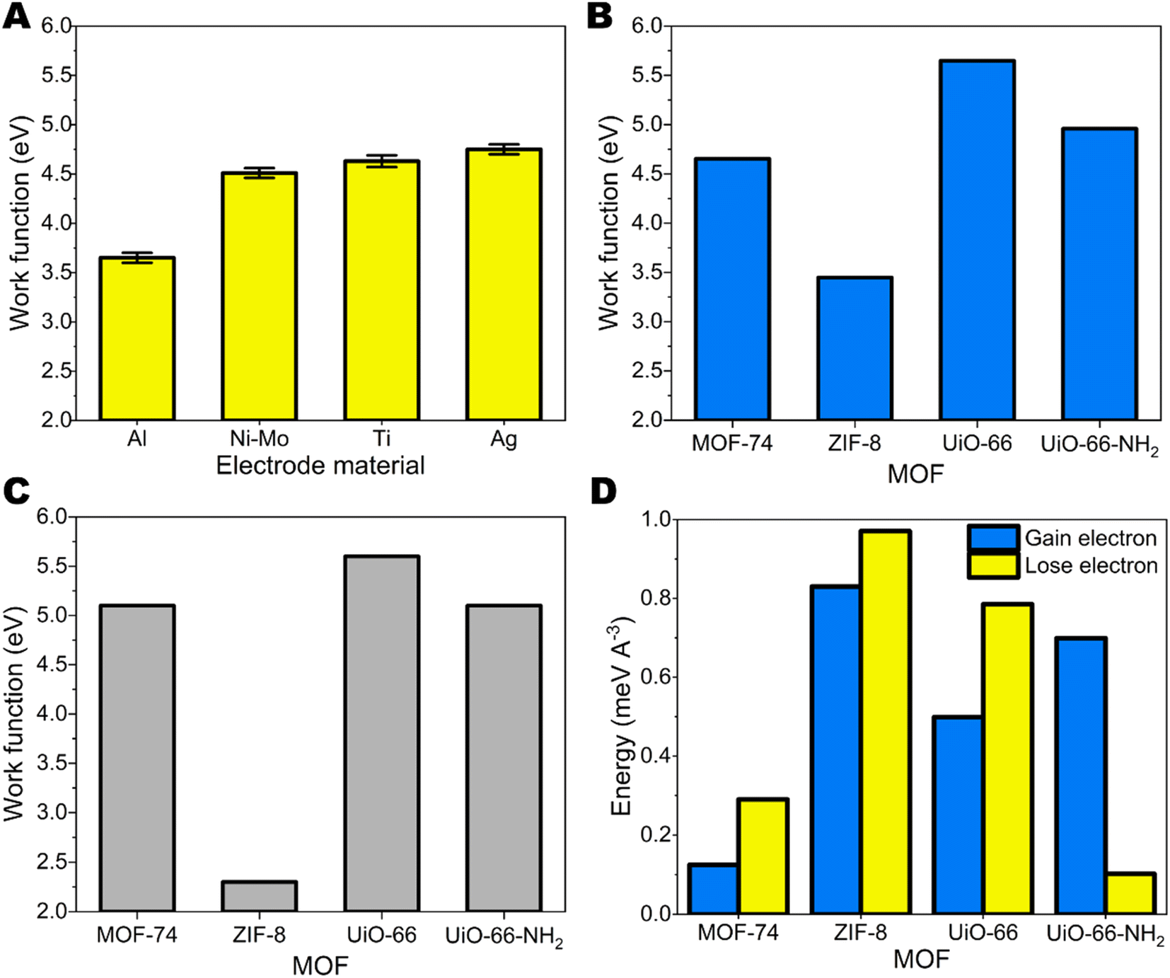 | ||
| Fig. 1 (A) The measured work function of Al, Ni–Mo, Ti and Ag electrodes; (B) the calculated work function of MOF-74, ZIF-8, UiO-66 and UiO-66-NH2. (C) The work function of MOF-74, ZIF-8, UiO-66 and UiO-66-NH2 obtained by UPS measurements. (D) Energy required to add or remove electron to a unit cell of a MOF structure. | ||
The schematic image of test setup is demonstrated in Fig. 2. (A) Representative current peak from metal-MOF contact-separation and charge density on MOFs after contacting with different metals are demonstrated in Fig. 2. (B–F) Negative charge on MOF means that MOF gains electron, while positive charge shows that MOF loses electron. Generally, electron transfer happens from the material with the lower work function to material with higher work function. Among studied MOFs, ZIF-8 has the smallest work function – smaller than every metal used in the study. Due to this reason, ZIF-8 is expected to gain positive charge after contacting-separating with metals because electrons are transferred to material with larger work function. In general, it is the case we are observing. ZIF-8 surface carry positive charge after contacting with Ti and Ag. There is negligible charge transfer between other metals with smaller work function which means that there is weak driving force for electronic charge transfer. Metals with large work functions should be used for ZIF-8 based TENG devices. The minor negative charge on ZIF-8 after contacting with Al could be due to the larger tendency to lose not to gain electrons by ZIF-8 as indicated by theoretical studies above.
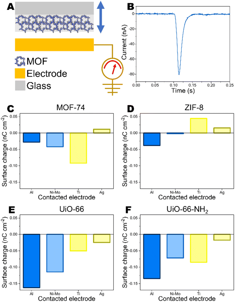 | ||
| Fig. 2 (A) Schematic of test setup used to determine the charge density of MOFs and (B) current peak generated during contact-separation of Al and UiO-66-NH2. Charge density of (C) MOF-74, (D) ZIF-8, (E) UiO-66 and (F) UiO-66-NH2 after contact-separation against Al, Ni–Mo, Ti and Ag electrodes. | ||
For a contact pair of Ag electrode and MOF-74 the observed charge is positive (Fig. 2C). The work functions of Ag and MOF-74 are very similar. Comparing the work functions of MOF-74 measured by UPS and calculated by DFT of MOF-74 with the work function of Ag indicates that technically both scenarios could be possible because UPS measured work function is lower, but DFT calculated work function of MOF-74 is higher than work function of Ag. For other MOF-metal pairs no differences can be observed concerning the use of either DFT-calculated or UPS-measured work function.
The triboelectric charge measurements correlate with the differences between work function values for MOFs and metals. The contact surface charge on MOF increases with increasing the difference between work function between MOF and metal. Among MOFs studied here, the highest work function is for UiO-66. Due to this reason it tends to gain strongest negative charge on surface when contacted with different metals and the charge is increasing when the difference between metal and MOF work function is increasing. Low work function metals for contacting with UiO-66 should be used.
The experimental correlations let us to assume that the electron transfer is the mechanism in contact between MOF and metal (Fig. 3A and B). To verify electron transfer mechanism, the residual charge on metal (Al) that had previously contacted MOF, was measured before and after grounding in non-contact mode. Before grounding a charge density of 1.84 pC cm−2 was measured (ESI Fig. S10†). However, only noise-level charge density of 0.08 pC cm−2 was observed on Al after grounding (ESI Fig. S11†) indicating that the electron transfer is the mechanism, not transfer of charged molecular pieces as it is in case of polymers.32 For comparison, Al electrode that had contacted PDMS showed charge density of 0.61 pC cm−2 before grounding and 0.52 pC cm−2 after grounding (ESI Fig. S12 and S13†). It has been observed before that the charged fragments from macromolecular chains from material transfer on conductors are stable and cannot be withdrawn by grounding.32
 | ||
| Fig. 3 Schematic of electron transfer when MOF has (A) higher work function than the contacted electrode and (B) lower work function than the contacted electrode. | ||
Conclusions
Different MOFs – MOF-74, ZIF-8, UiO-66 and UiO-66-NH2 were successfully synthesized. MOF materials under the study exhibit triboelectric charging when contacted with the metal. The stronger electrification can be expected when there is the larger difference between work function of metal and MOF due to larger driving force for transfer. Experimental results indicate that the main mechanism for MOF triboelectrification is electron transfer.Conflicts of interest
There are no conflicts to declare.Acknowledgements
This work was funded by Latvian-Lithuanian-Taiwan Scientific Cooperation Support Fund (LV-LT-TW/2021/3) represented by the Research Council of Lithuania (Project Nr. S-LLT-21-2) and Latvian Council of Science (Project Nr. 03000-3.1.2.1-e/3). Fa-Kuen Shieh would like to thank the Ministry of Science and Technology, Taiwan, for funding support (MOST 110-2923-M-008-002-MY3). Part of the measurements were performed on equipment located at the Center of Excellence at the Institute of Solid State Physics, University of Latvia, which is supported by European Union's Horizon 2020 Framework Programme H2020-WIDESPREAD-01-2016-2017-TeamingPhase2 under Grant Agreement No. 739508, project CAMART2. O. Verners acknowledges support by the European Regional Development Fund within the Activity 1.1.1.2 “Post-doctoral Research Aid” of the Specific Aid Objective 1.1.1 “To increase the research and innovative capacity of scientific institutions of Latvia and the ability to attract external financing, investing in human resources and infrastructure” of the Operational Programme “Growth and Employment” (No.1.1.1.2/VIAA/4/20/636). O. Verners acknowledges Riga Technical University's HPC Center for providing access to their computing infrastructure.Notes and references
- F. R. Fan, Z. Q. Tian and Z. L. Wang, Nano Energy, 2012, 1, 328 CrossRef CAS.
- W. Tang, T. Jiang, F. R. Fan, A. F. Yu, C. Zhang, X. Cao and Z. L. Wang, Adv. Funct. Mater., 2015, 25, 3718 CrossRef CAS.
- R. Lei, Y. Shi, Y. Ding, J. Nie, S. Li, F. Wang, H. Zhai, X. Chen and Z. L. Wang, Energy Environ. Sci., 2020, 13, 2178 RSC.
- J. Tian, F. Wang, Y. Ding, R. Lei, Y. Shi, X. Tao, S. Li, Y. Yang and X. Chen, Research, 2021, 2021, 8564780 CrossRef CAS PubMed.
- X. Xia, Q. Liu, Y. Zhu and Y. Zi, EcoMat, 2020, 2, e12049 CrossRef CAS.
- X. Pu, M. Liu, L. Li, C. Zhang, Y. Pang, C. Jiang, L. Shao, W. Hu and Z. L. Wang, Adv. Sci., 2016, 3, 1500255 CrossRef.
- A. U. Ortiz, A. P. Freitas, A. Boutin, A. H. Fuchs and F.-X. Coudert, Phys. Chem. Chem. Phys., 2014, 16, 9940 RSC.
- J. Ren, Y. Huang, H. Zhu, B. Zhang, H. Zhu, S. Shen, G. Tan, F. Wu, H. He, S. Lan, X. Xia and Q. Liu, Carbon Energy, 2020, 2, 176 CrossRef CAS.
- R. Banerjee, A. Phan, B. Wang, C. Knobler, H. Furukawa, M. O'Keeffe and O. M. Yaghi, Science, 2008, 319, 939 CrossRef CAS PubMed.
- J. W. Liu, L. F. Chen, H. Cui, J. Y. Zhang, L. Zhang and C. Y. Su, Chem. Soc. Rev., 2014, 43, 6011 RSC.
- J.-R. Li, J. Sculley and H.-C. Zhou, Chem. Rev., 2012, 112, 869 CrossRef CAS.
- G. Khandelwal, N. P. M. J. Raj and S.-J. Kim, Adv. Funct. Mater., 2020, 30, 1910162 CrossRef CAS.
- G. Khandelwal, A. Chandrasekhar, N. P. M. J. Raj and S.-J. Kim, Adv. Energy Mater., 2019, 9, 1803581 CrossRef.
- G. Khandelwal, N. P. M. J. Raj and S.-J. Kim, J. Mater. Chem. A, 2020, 8, 17817 RSC.
- Y. Guo, Y. Cao, Z. Chen, R. Li, W. Gong, W. Yang, Q. Zhang and H. Wang, Nano Energy, 2020, 70, 104517 CrossRef CAS.
- S. Hajra, M. Sahu, A. M. Padhan, I. S. Lee, D. K. Yi, P. Alagarsamy, S. S. Nanda and H. J. Kim, Adv. Funct. Mater., 2021, 31, 2101829 CrossRef CAS.
- Y.-M. Wang, X. Zhang, D. Yang, L. Wu, J. Zhang, T. Lei and R. Yang, Nanotechnology, 2021, 33, 065402 CrossRef.
- R. Wen, J. Guo, A. Yu, J. Y. Zhai and Z. L. Wang, Adv. Funct. Mater., 2019, 29, 1807655 CrossRef.
- Y. Guo, Y. Cao, Z. Chen, R. Li, W. Gong, W. Yang, Q. Zhang and H. Wang, Nano Energy, 2020, 70, 104517 CrossRef CAS.
- G. Khandelwal, N. P. Maria Joseph and S.-J. Kim, Adv. Energy Mater., 2021, 11, 2101170 CrossRef CAS.
- A. Šutka, K. Mālnieks, L. Lapčinskis, P. Kaufelde, A. Linarts, A. Bērziņa, R. Zābels, V. Jurķāns, I. Gorņevs, J. Blūms and M. Knite, Energy Environ. Sci., 2019, 12, 2417 RSC.
- L. Lapčinskis, K. Mālnieks, J. Blūms, M. Knite, S. Oras, T. Käämbre, S. Vlassov, M. Antsov, M. Timusk and A. Šutka, Macromol. Mater. Eng., 2020, 305, 1900638 CrossRef.
- T. Mazur and B. A. Grzybowski, Chem. Sci., 2017, 8, 2025 RSC.
- K. Kida, M. Okita, K. Fujita, S. Tanaka and Y. Miyake, CrystEngComm, 2013, 15, 1794 RSC.
- Y. H. Huang, W. S. Lo, Y. W. Kuo, W. J. Chen, C. H. Lin and F. K. Shieh, Chem. Commun., 2017, 53, 5818 RSC.
- J. Shi, F. Chen, L. Hou, G. Li, Y. Li, X. Guan, H. Liu and L. Guo, Appl. Catal., B, 2021, 280, 119385 CrossRef CAS.
- C. L. Luu, T. Nguyen, A. P. Nguyen, C. T. Hoang and A. C. Ha, Adv. Nat. Sci.: Nanosci. Nanotechnol., 2020, 11, 035008 Search PubMed.
- J. Sans, M. Arnau, F. Estrany, P. Turon and C. Alemán, Adv. Mater. Interfaces, 2021, 8, 2100163 CrossRef CAS.
- P. Giannozzi, O. Andreussi, T. Brumme, O. Bunau, M. Buongiorno Nardelli, M. Calandra, R. Car, C. Cavazzoni, D. Ceresoli, M. Cococcioni, N. Colonna, I. Carnimeo, A. Dal Corso, S. de Gironcoli, P. Delugas, R. A. DiStasio, A. Ferretti, A. Floris, G. Fratesi, G. Fugallo, R. Gebauer, U. Gerstmann, F. Giustino, T. Gorni, J. Jia, M. Kawamura, H.-Y. Ko, A. Kokalj, E. Kücükbenli, M. Lazzeri, M. Marsili, N. Marzari, F. Mauri, N. L. Nguyen, H.-V. Nguyen, A. Otero-de-la-Roza, L. Paulatto, S. Ponce, D. Rocca, R. Sabatini, B. Santra, M. Schlipf, A. P. Seitsonen, A. Smogunov, I. Timrov, T. Thonhauser, P. Umari, N. Vast, X. Wu and S. Baroni, J. Phys.: Condens. Matter, 2017, 29, 465901 CrossRef CAS.
- P. Giannozzi, S. Baroni, N. Bonini, M. Calandra, R. Car, C. Cavazzoni, D. Ceresoli, G. L. Chiarotti, M. Cococcioni, I. Dabo, A. Dal Corso, S. de Gironcoli, S. Fabris, G. Fratesi, R. Gebauer, U. Gerstmann, C. Gougoussis, A. Kokalj, M. Lazzeri, L. Martin-Samos, N. Marzari, F. Mauri, R. Mazzarello, S. Paolini, A. Pasquarello, L. Paulatto, C. Sbraccia, S. Scandolo, G. Sclauzero, A. P. Seitsonen, A. Smogunov, P. Umari and R. M. Wentzcovitch, J. Phys.: Condens. Matter, 2009, 21, 395502 CrossRef.
- K. Deevi and V. S. R. Immareddy, J. Mater. Sci.: Mater. Electron., 2019, 30, 6242 CrossRef CAS.
- P. C. Sherrell, A. Sutka, N. A. Shepelin, L. Lapcinskis, O. Verners, L. Germane, M. Timusk, R. A. Fenati, K. Malnieks and A. V. Ellis, ACS Appl. Mater. Interfaces, 2021, 13, 44935 CrossRef CAS.
Footnote |
| † Electronic supplementary information (ESI) available: 1 Table and 9 Figures. See DOI: https://doi.org/10.1039/d2ra06150c |
| This journal is © The Royal Society of Chemistry 2023 |