Macroscopic alignment of metal–organic framework crystals in specific crystallographic orientations
Jonghoon
Park
a,
Hoi Ri
Moon
 *b and
Jin Yeong
Kim
*c
aDepartment of Chemistry, Ulsan National Institute of Science and Technology (UNIST), 50 UNIST-gil, Ulsan 44919, Republic of Korea
bDepartment of Chemistry and Nanoscience, Ewha Womans University, 52 Ewhayeodae-gil, Seoul 03760, Republic of Korea. E-mail: hoirimoon@ewha.ac.kr
cDepartment of Chemistry Education, Seoul National University, Seoul 08826, Republic of Korea. E-mail: jykim@snu.ac.kr
First published on 22nd August 2023
Abstract
With the growing interest in metal–organic frameworks (MOFs) and their potential applications, it has become crucial to discover novel MOFs and modify their constituent components. One promising strategy for enhancing the properties of MOFs is the alignment of crystals in specific orientations, which induce anisotropic properties in particular facets. The integration of oriented MOFs at the macroscopic level can be achieved through two main approaches: the direct growth in an oriented manner and the alignment of pre-formed crystals. Direct growth methods involve the adsorption of precursor molecules on substrates, initiating the guided growth based on factors like lattice parameters, surface interactions, and differential growth rates of crystal facets. Integrating MOFs with other substrates in an oriented manner generates novel architectures with unique properties. Another approach is to create alignment using pre-formed MOF crystals, which mainly involves external forces, interfaces of synthetic media, and their assembly. This strategy offers greater flexibility in material selection because of the wide range of pre-existing MOF structures of different compositions. Furthermore, it enables the fabrication of highly ordered alignment over large areas. Ideally, perfectly aligned MOF crystals can mutually synchronize with each other to act like a large single-crystal, ultimately facilitating the full utilization of the directional anisotropic properties over a large area. This review focuses on the preparation strategies and examples of macroscopically oriented MOFs.
1. Introduction
Metal–organic frameworks (MOFs) are crystalline porous materials constructed by connecting metal ions/clusters and multitopic ligands.1–7 They have attracted significant attention owing to their fascinating properties and versatile applications, including molecular separation and storage,8–20 catalysis,21–26 optics,27–29 and sensing.30–34 The combination of metal nodes and organic linkers allows for the creation of customizable pore structures within ordered arrangements,1–3,5,6,35 catering to specific application requirements.36–38 Over the past three decades, researchers have developed various strategies to tailor the properties of MOFs, such as exploring novel MOF structures,39 conducting post-synthetic modifications,40–47 and incorporating composites.48 Recently, a promising method called MOF crystal alignment has emerged, enhancing MOF properties without the need for new structural designs or post-synthetic reactions. By assembling and aligning individual crystallites, the inherent anisotropic properties can be synchronized and extended, resulting in overall performance enhancement. Consequently, in the past two decades, there has been a growing research interest in MOF crystals that demonstrate directional orientation during growth or assembly.Typically, oriented MOFs with a specific direction can be achieved through direct growth on substrates or by aligning pre-formed crystals.49,50 Substrate-assisted methods involve precursor molecule adsorption on substrates, guiding the growth of MOF crystals based on factors like substrate lattice parameters,51 surface interactions,52 and differential growth rates of crystal facets.53,54 This approach assembles building blocks directly onto functional substrates, yielding tailored structures and novel architectures when integrated with other substrates. Another approach utilizes external forces like electric and magnetic fields, interfacial tension, and capillary and depletion forces to guide the orientation of pre-formed MOF crystals.49,50,55 Using pre-formed crystals offers flexibility in material selection and ensures consistent starting points for size, shape, and morphology, enabling the fabrication of highly ordered orientations in large quantities.39,55 Self-assembly of polyhedral MOF particles with distinct facets leads to the formation of oriented structures, allowing full utilization of directional anisotropic properties over a large area. Precise arrangement of pre-formed MOF crystals enhances their functionalities, expanding their applications.49
Aligned MOF crystals selectively expose specific facets, maximizing their anisotropic properties and leading to improved characteristics, such as permeability, diffusivity, selectivity, conductivity, catalytic properties, optical properties, and wettability.49,50 One prominent example is the improved molecular separation achieved through controlled alignment.56–58 By aligning MOF crystals in a specific direction, precise pathways for guest molecules can be engineered, resulting in superior selectivity and mass transport. Catalysis also benefits from the ordered alignment, as it enhances accessibility to active sites, leading to improved catalytic activity and selectivity.59,60 Additionally, the aligned MOFs enable enhanced pathways for ions and electrons, which is advantageous for applications such as sensors, electrochemical catalysts, and electronic devices.61,62 Although research on directional MOFs is still in its early stages, these examples illustrate the vast potential of macroscale aligned MOFs in tailoring and enhancing their properties for various technological applications.
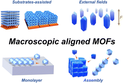
This review focuses on advancements in preparing macroscopically oriented MOFs in a specific direction (Fig. 1). It emphasizes the alignment of MOF crystals at the macroscopic level rather than the directional growth at the single crystal level such as core–shell structures. Single-crystalline core–shell crystals were successfully obtained by sequentially synthesizing MOFs after preparing single-crystalline MOF substrates, in which the crystal lattice parameters of these substrates are crucial for guiding the growth of the desired MOF. However, studies on synthesis of single-crystalline core–shell crystals are beyond the scope to be covered in this review, and the recent advancements in this area have been well-summarized in the review papers.63–65 This review covers various preparation strategies and provides examples based on the alignment-driving approaches, including substrate-assisted methods, external forces, interfaces, and assembly techniques. The aim of this review is to provide insight into the construction of oriented MOFs to enable the realization of advanced applications in this field.
2. Alignment of MOF crystals on substrates
In direct growth of MOFs in ordered manner, the substrates play an important role in determining the alignment directions of MOFs. By carefully controlling the synthesis conditions and precisely arranging the building blocks, these strategies provide a promising way to tailor the crystallographically prepared orientations of MOFs and enable the design of advanced structures with enhanced functionality. The promotion of orientation in MOF crystals can be achieved through the epitaxial growth on substrates possessing lattice matching or by employing covalent or non-covalent interactions between the substrate and MOF constituents.51,52 Even in the absence of specific interactions, MOFs grown on substrates tend to exhibit competitive growth, resulting in the formation of oriented structures.53,54 Two-dimensional (2D) architectures obtained from the crystal growth on the substrates can provide significant advantages in device fabrication such as MOF films and membranes.49,66–71An approach to achieving macroscopic epitaxial growth of oriented 2D film of MOFs involves initially depositing seed MOF crystals onto substrates, followed by subsequent growth of these identical crystals (Fig. 2a). In the study conducted by Liu et al. seed crystals of ZIF-69 were densely deposited on an alumina substrate using a dip coating technique (Fig. 2b, left).72 The hexagonal prism-like crystals are aligned in [001] axis nearly parallel to the out-of-plane direction on the substrate, with a slight tilt. The seed-coated substrate was then immersed in a precursor solution to facilitate secondary growth. Due to the guidance of the ZIF-69 seeds, the resulting ZIF-69 film exhibited preferential growth (Fig. 2b, right), evidenced by the distinct (002) peak in the X-ray diffraction (XRD) pattern. On the other hand, precise control over the seed morphology and the creation of a consistent layer via oriented seeding can lead to the effective epitaxial growth of crystals during the secondary growth for highly oriented films. As an illustration, highly oriented NH2-MIL-125(Ti) and ZIF-7 films were cultivated via this approach, where finely developed seeds of them were dynamically assembled, facilitating even deposition onto a substrate.57,73
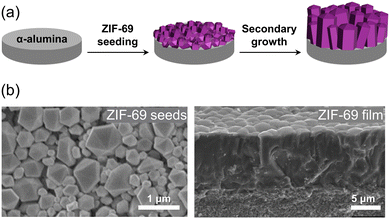 | ||
| Fig. 2 (a) Schematic illustration of the process for synthesizing an oriented ZIF-69 film on an α-alumina substrate by seeding ZIF-69 crystals and subsequent secondary growth. (b) SEM image of ZIF-69 seeds on the substrate (left) and cross-section of the oriented ZIF-69 film grown through secondary growth (right). Adapted with permission (part of figures) from ref. 72. Copyright 2011, Elsevier. | ||
The seed guiding the orientation of crystal growth does not necessarily have to be a MOF crystal itself; it can also be a metallic precursor that serves the dual role of the sacrificial agent and the inorganic substrate. Takahashi et al. reported centimetre scale of oriented Cu2(BDC)2 (BDC: 1,4-benzenedicarboxylate) MOF films by the heteroepitaxial growth on Cu(OH)2 nanobelts assembled on a Si wafer.74 Cu(OH)2 nanobelts were assembled in a 2D manner along both the in-plane and out-of-plane directions at the water–air interface and then transferred onto the Si wafer. Because the a- and b-axes (a = 10.61 Å and b = 5.80 Å) of Cu2(BDC)2 are twice the c- and a-axes of Cu(OH)2, respectively, the synthesized Cu2(BDC)2 film epitaxially grown on the substrate exhibited a full orientation in both out-of-plane and in-plane directions resembling that of the Cu(OH)2 substrate (Fig. 3a). Scanning electron microscopy (SEM) and XRD analysis revealed that the aligned growth of MOFs where (00l) plane of Cu2(BDC)2 were observed in the out-of-plane direction of the substrate, while the (h00) and (0k0) plane were observed in the in-plane parallel and perpendicular directions, respectively, demonstrating a three-dimensional (3D) orientation (Fig. 3b–d). The same orientation trend was observed for Cu2(BDC)2(DABCO) (DABCO: 1,4-diazabicyclo[2.2.2]octane), where DABCO was added as a pillar to the MOF structure. Other Cu-MOFs with different ligands, such as 2,6-NDC and BPDC (NDC: 1,4-naphthalenedicarboxylate; BPDC: biphenyl-4,4′-dicarboxylate), which have lattice mismatches of less than 2% with Cu(OH)2 substrates, also exhibited the same orientation trend. This method allows to produce MOF films with a three-dimensional alignment on a centimetre scale. In order to demonstrate the distinctive anisotropic characteristics of the MOFs grown heteroepitaxially, a fluorescent dye capable of aligning with a particular crystallographic plane of the MOF film was employed. The brightness of the fluorescent response was dependent on the angle formed between the linearly polarized excitation radiation and the crystal lattice planes. As a result, simply by modifying the rotation of the MOF film, it was possible to switch the fluorescent signal ‘ON’ or ‘OFF’.
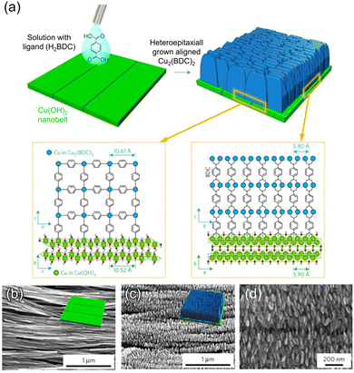 | ||
| Fig. 3 (a) A schematic illustration inducing the heteroepitaxial growth of Cu2(BDC)2 on 2D substrate of Cu(OH)2 by reacting H2BDC solution with Cu(OH)2. SEM images of (b) 2D substrate of Cu(OH)2 and epitaxially grown Cu2(BDC)2 film on Cu(OH)2 with (c) low and (d) high magnification. Adapted with permission from ref. 74. Copyright 2017, Springer Nature. | ||
This strategy can be extended to applications of epitaxial growth of photosensitive MOF films on Cu(OH)2 and patterning of oriented MOF films via photolithography. Velásquez-Hernández et al. reported the fabrication of an oriented photosensitive Cu2[(Br2BDC)x(BDC)1−x]2DABCO ((Br2BDC: 2,5-dibromo-1,4-benzenedicarboxylate) film on Cu(OH)2 (Fig. 4a).75 The inclusion of Br2BDC in the MOF film facilitated the homolytic cleavage of the C–Br bonds, making the film sensitive to X-ray radiation. A uniformly oriented MOF film containing a high concentration of photosensitive ligands is obtained at a Br2BDC![[thin space (1/6-em)]](https://www.rsc.org/images/entities/char_2009.gif) :
:![[thin space (1/6-em)]](https://www.rsc.org/images/entities/char_2009.gif) BDC ratio of 0.96
BDC ratio of 0.96![[thin space (1/6-em)]](https://www.rsc.org/images/entities/char_2009.gif) :
:![[thin space (1/6-em)]](https://www.rsc.org/images/entities/char_2009.gif) 0.04. Consequently, using a photomask under X-ray exposure, the oriented MOF film was decomposed in the irradiated areas and kept intact in the unexposed areas, thus creating diverse micropatterns (Fig. 4b).
0.04. Consequently, using a photomask under X-ray exposure, the oriented MOF film was decomposed in the irradiated areas and kept intact in the unexposed areas, thus creating diverse micropatterns (Fig. 4b).
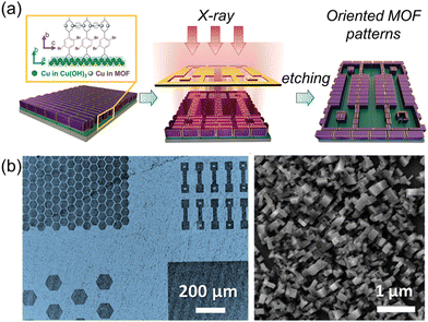 | ||
| Fig. 4 (a) A schematic illustration of the patterning of oriented MOF films via photolithography. (b) Optical image of micropatterned Cu2[(Br2BDC)x(BDC)1−x]2DABCO oriented film on Cu(OH)2 (left) and SEM image of oriented MOFs in the unexposed area to X-ray (right). Adapted with permission from ref. 75. Copyright 2023, Wiley-VCH. | ||
Even in the absence of matching lattice parameters, it is still feasible to achieve directional growth of a MOF by utilizing a substrate surface with a high concentration of interaction sites. These interaction sites serve as guides, enabling the MOF to grow in a specific direction. Self-assembled monolayer (SAM) technique can provide high density of interaction site on a substrate.76,77 The technique of self-assembled monolayers (SAM) offers a means to achieve a high density of interaction sites on a substrate as coordination motifs of MOFs. Bein's group proposed a pioneering approach for directional HKUST-1 crystal growth using SAMs functionalized with HS(CH2)10X (X = –COOH, –CH2OH, and –CH3) on Au(111) substrate (Fig. 5a).78 In this study, depending on a type of terminal groups of SAMs the MOFs grown on them show the different alignment tendency. The –COOH terminated SAM induced HKUST-1 growth in the [100] crystal orientation along the out-of-plane direction, while the –CH2OH functionalized SAM led to HKUST-1 growth in the [111] crystal orientation along the out-of-plane direction (Fig. 5b). However, the –CH3 terminated SAM did not exhibit any discernible alignment preference in a particular direction, having the similar XRD patterns with those of the bulk powder sample. These alignment phenomena are attributed to the coordination of MOF precursors with the –COOH and –OH groups in the SAM, mimicking the structural roles of organic ligands and H2O in HKUST-1, respectively. The carboxylic acid terminated SAM also successfully aligned a flexible MOF, Fe-MIL-88B.79 In addition to the aforementioned carboxylate-based SAMs, pyridine-based SAMs are also effective for the orientation of MOFs. In the study conducted by Zhuang et al.,80 (4-(4-pyridyl)phenyl)phenyl)methanethiol (PPP1) was used as a SAM to orient [Cu2(F4BDC)2(DABCO)] (F4bdc: tetrafluorobenzene-1,4-dicarboxylate) onto a substrate. The N atom in the pyridine group of PPP1 coordinates one Cu2+ in the paddle-wheel cluster of the MOF. This coordination induces parallel orientations of the Cu paddle wheel within the MOF, resulting in the alignment of the (001) planes of the MOF in parallel to the substrate.
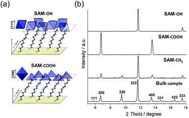 | ||
| Fig. 5 (a) Schematic illustration of [111] oriented HKUST-1 crystals with –OH SAM and [100] oriented HKUST-1 crystals with the –COOH SAM in the film. (a) XRD patterns of bulk and oriented films of HKUST-1 depending on the SAM functional groups. Adapted with permission from ref. 78. Copyright 2007, American Chemical Society. | ||
SAM-modified substrates were utilized for the growth of surface-mounted MOFs (SURMOFs) via sequential immersion in metal precursor and ligand solutions to form thin MOF films in a layer-by-layer (LBL) manner. This combined approach of SAM and LBL offers advantages of oriented MOF film with uniform surfaces and controlled thicknesses. Moreover, it facilitates the epitaxial growth of alternative MOF films that possess distinct lattice parameters compared to the substrate MOFs (Fig. 6). Wöll et al. synthesized heteroepitaxial SURMOFs with large lattice mismatches.81 They sequentially grew isoreticular Cu-BPDC, Cu-NDC, and Cu-BDC SURMOFs on the substrate, despite their lattice mismatches of 15.7% between Cu-BPDC and Cu-NDC and 19.6% between Cu-NDC and Cu-BDC. Quantum chemical calculations unveiled that the vacancies formed at the interfaces of the MOFs, resulting from lattice mismatches, were effectively coordinated with the acetate anions present in the precursor solution. This coordination served to enhance energetic stability. XRD patterns of the SURMOFs displayed distinct peaks corresponding to the (001) and (002) planes of each MOF, confirming the oriented growth.
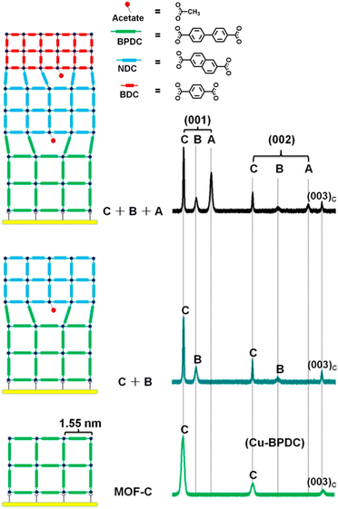 | ||
| Fig. 6 Schematic diagram depicting the step-by-step hetero-epitaxial growth of SURMOFs with a significant lattice mismatch, accompanied by XRD patterns illustrating the orientation of MOFs at each step. Adapted with permission from ref. 81. Copyright 2014, American Chemical Society. | ||
There have been examples that non-covalent interactions, such as hydrogen bonding, van der Waals forces, dipole–dipole interactions, and π–π stacking interactions, guide the orientation of MOFs grown on substrates.49,55 For instance, when graphene oxide (GO) is used as a substrate, localized interactions take place between the functional groups present in GO and the MOF components. This interaction allows GO to be effectively utilized as a substrate while enabling the growth of vertically aligned nanosheets and creating a foam-like 2D architecture (Fig. 7a). Liu et al. reported that when the functional groups of GO were treated with 2-methylimidazole (2-MeIM), the surface of GO is decorated with 2-MeIM via local electrostatic interactions (Fig. 7b).82 Subsequently, ZIF-67 was grown on the pretreated GO via a reaction in the precursor solution. Transmission electron microscopy (TEM) images of the product revealed ZIF-67 was vertically aligned on GO as nanosheets, and high-resolution TEM images showed lattice fringes corresponding to the (002) plane of ZIF-67. It indicated that the ZIF-67 nanosheets are oriented on the GO substrate such that their (002) planes are perpendicular to the substrate. This foam-like architecture is beneficial for Li+ storage in batteries.
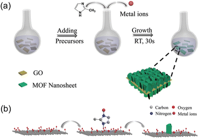 | ||
| Fig. 7 Schematic illustrations of (a) the synthesis for ZIF-67 nanosheets on GO substrate, as well as (b) the process of achieving vertically oriented nanosheets. Adapted with permission from ref. 82. Copyright 2020, Wiley-VCH. | ||
When MOF precursors are introduced at the water–air interface, water acts as a soft substrate for oriented MOF growth through surface interactions. Kitagawa et al. fabricated a perfect preferentially oriented 2D MOF film CoTCPP-py-Cu (NAFS-1) (CoTCPP: [5,10,15,20-tetrakis(4-carboxyphenyl)porphyrinato]cobalt(II); Py: pyridine) using a modular approach that combines the Langmuir–Blodgett and LBL stacking methods (Fig. 8a).83 NAFS-1 was synthesized at the water–air interface by introducing a ligand-containing organic solution onto the metal ion-containing water. The use of Langmuir–Blodgett methods achieved the perfect orientation of NAFS-1 parallel to the soft substrate (water), and it was subsequently deposited onto a hard substrate (Si) in a sequential LBL fashion through π–π interactions. NAFS-1 exhibited highly crystalline order in both out-of-plane and in-plane orientations towards the substrate, as confirmed by synchrotron X-ray surface crystallography. The unique structural model of NAFS-1 includes metal-coordinated pyridine molecules that act as docking sites, facilitating the highly ordered interdigitated growth of each successive layer through the LBL process (Fig. 8b). Recently, this strategy was extended to produce an oriented conductive 2D MOF, Ni3(HITP)2 (HITP: 2,3,6,7,10,11-hexaiminotriphenylene), on a substrate.58 This solution-based growth strategy holds promise to produce well-ordered MOF nanofilms.
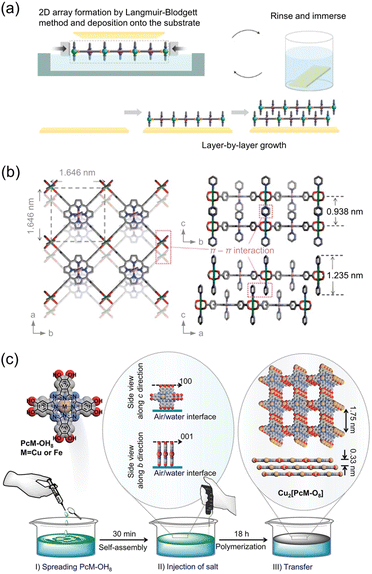 | ||
| Fig. 8 (a) Schematic illustration of layer-by-layer (LBL) assembly for oriented NAFS-1 film and (b) structural model representing the stacking of 2D MOF sheets in the film with the precise position of coordinated pyridine molecules. Adapted with permission from ref. 83. Copyright 2010, Springer Nature. (c) Schematic illustration of the vertically arranged PcCu–OH8 at the water–air interface, followed by injection of Cu precursor solution for vertically oriented MOF film assembly. Reproduced from ref. 84. Copyright 2021, American Chemical Society. | ||
Through the water–air assembly, Wang et al. made a remarkable discovery by successfully synthesizing a 2D MOF with vertically aligned sheets on a substrate (Fig. 8c).84 Initially, they spread (2,3,9,10,16,17,23,24-octahydroxyphthalocyaninato)copper(II) (PcCu–OH8) on the interface between water and air and allowed it to rest for 30 min. During this resting period, the PcCu–OH8 units arranged themselves perpendicular to the water–air interface and assembled through π–π stacking, facilitated by the presence of hydrophilic –OH groups and hydrophobic phthalocyanine components. Subsequently, a Cu precursor solution was injected to synthesize Cu2[PcCu–O8]. The perpendicular alignment of the PcCu–OH8 units was maintained even after the MOF assembly and deposition onto the substrate. The vertical alignment of the MOF on the substrate was confirmed using grazing-incidence wide-angle X-ray scattering (GIWAXS). The peak corresponding to the (001) plane was observed in the in-plane pattern but not in the out-of-plane pattern, indicating the presence of vertically stacked sheets with AA-stacking.
In cases where the seed MOFs are deposited randomly on the substrate or when the substrates lack specific interaction sites, the synthesis of MOFs with specific orientations can still be achieved through competitive growth.53,54 This process leverages the differential growth rates of crystal planes to direct the orientation of MOF formation. To address this, vapor-assisted conversion (VAC) and chemical vapor deposition (CVD) have been employed for a secondary growth. In an early study by Li et al., oriented ZIF-7 films were synthesized by utilizing the differential growth rates of crystal planes of randomly oriented ZIF-7 nanocrystal seeds.85 The process involved immersing a substrate randomly coated with ZIF-7 seeds in a precursor solution of ZIF-7 and subjecting it to a microwave-assisted reaction for secondary growth. The outcome was the formation of a well-oriented ZIF-7 film, as depicted in Fig. 9. Throughout the reaction, the intensity of the (101) plane peak in the XRD patterns progressively increased, indicating the growth of ZIF-7 driven by specific orientation through van der Drift growth, despite the initial random orientation of the ZIF-7 seeds. This approach was further successfully employed to fabricate ZIF-8 films exhibiting a favorable alignment.86
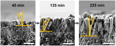 | ||
| Fig. 9 SEM images depending on different reaction times representing the extent of secondary growth of ZIF-7 in the out-of-plane direction with a tilted way from ZIF-7 nanocrystals on an alumina substrate. Adapted with permission from ref. 85. Copyright 2010, Wiley-VCH. | ||
The VAC method has been used to obtain oriented Zr-based MOFs by exposing uniformly deposited MOF precursors to a solvent gas.87 This approach ensures even distribution and promotes uniform growth across the substrate. Oriented Zr-based MOF films such as UiO-66, UiO-66-NH2, UiO-67, and PPPP-PIZOF-1 have been successfully grown on gold substrates using VAC. Additionally, vertically or horizontally aligned MOF-74 films have been achieved on various substrates by incorporating different metal ions, Mg2+ and Zn2+ respectively, into the precursor solution (Fig. 10a and b).88 These orientation phenomena were observed regardless of the substrate type, highlighting that the presence of different metal ion species in the precursor solution was responsible for the variations in orientation. Ameloot et al. demonstrated the potential for obtaining oriented MOF films using CVD.89 Using CVD, the pre-deposited CuO on a Si substrate was reacted with evaporated H2CDC and H2BDC (H2CDC: trans-1,4-cyclohexanedicarboxylic acid; H2BDC: terephthalic acid) to form CuCDC and CuBDC films, respectively (Fig. 10c). Cross-sectional SEM images of CuCDC showed that the CuO layer, regardless of its initial thickness, transformed into a MOF film within a range of 10–15 nm. Grazing incidence X-ray diffraction (GIXRD) confirmed the orientation of the CuCDC and CuBDC films on the (100) plane parallel to the substrate.
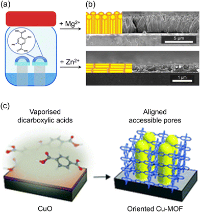 | ||
| Fig. 10 (a) Schematic illustration of VAC reactions for MOF-74 films with Mg2+ or Zn2+ as a metal source. (b) Cross-sectional SEM images of Mg-MOF-74 film (top) and Zn-MOF-74 film (down). Adapted with permission from ref. 88. Copyright 2021, American Chemical Society. (c) Schematic illustration of the CVD process for synthesizing oriented films of CuCDC and CuBDC by reacting a deposited layer of CuO with a vaporized carboxylic acid. Adapted with permission from ref. 89. Copyright 2019, Royal Society of Chemistry. | ||
Selective deposition of MOF precursors on a 2D substrate, followed by crystal growth, enables the fabrication of MOF patterns aligned in a specific direction. Ameloot et al. achieved oriented HKUST-1 patterns by manipulating the crystallization kinetics of HKUST-1 crystals.90 A solution containing precursors was deposited onto a functionalized glass substrate, and a polydimethylsiloxane (PDMS) stamp was placed on top, creating a confined space (Fig. 11a). Capillary forces guided the solution into the confined space, resulting in the oriented growth of HKUST-1 crystals as the solvent evaporated. Notably, irrespective of the functional groups on the substrate, such as silanol, vinyl, or carboxylic acid groups, the HKUST-1 crystals consistently exhibited the same orientation with the (111) plane parallel to the substrate (Fig. 11b). Zhuang et al. developed a novel printing technique for the facile fabrication of (111)-oriented HKUST-1 films on various substrates (Fig. 11c and d).91 This method demonstrated versatility, accommodating a wide range of substrates including plastics, paper, and textiles, and allowing for multiple printing steps. The printed substrate was exposed to methanol vapor, promoting a slower nucleation process. This resulted in truncated octahedral crystals with a [111] crystal orientation aligned parallel to the out-of-plane direction of the substrate, as confirmed by XRD patterns.
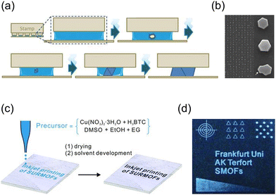 | ||
| Fig. 11 (a) Schematic illustration for the formation of oriented HKUST-1 crystals after solvent evaporation in precursor solution within a confined space created by a PDMS stamp. (b) SEM image of the oriented HKUST-1 film with low and high magnification. Adapted with permission from ref. 90. Copyright 2010, Wiley-VCH. (c) Scheme of printing process with a precursor solution of HKUST-1 as an ink and (d) HKUST-1 film obtained through printing. Adapted with permission ref. 91. Copyright 2013, Wiley-VCH. | ||
3. Alignment of MOF crystals via external field
The development of oriented MOFs using external fields such as electric and magnetic fields has recently gained significant attention. These approaches utilize pre-formed MOF crystals, which overcome the limitations associated with direct growth methods that require extensive substrate preparation or time-consuming re-optimization of growth conditions. Randomly positioned anisotropic MOF particles can effectively acquire a directional orientation through particle magnetization and subsequent exposure to a magnetic field. NH2-MIL-53(Al) with an aspect ratio of 21 ± 7 and NU-1000 with an aspect ratio of 5.9 ± 0.9 were magnetically functionalized by leveraging the attractive force between MOFs and iron oxide nanoparticles at a pH of 3.5.92 The resulting NH2-MIL-53(Al) and NU-1000 composites exhibited magnetic susceptibility of 9.09 × 10⁻⁶ and 5.79 × 10⁻⁶ m3 kg−1, respectively. Under a magnetic field, both composites were oriented with their main axes parallel to the magnetic field and did not aggregate, and the arrangement changed dynamically according to the direction of the magnetic field (Fig. 12a). When the magnetized MOF crystals were dispersed in the photocurable polymer resins, those were well-aligned in the magnetic field and fixed in the resin. Furthermore, the incorporation of fluorescent planar pyrene ligands along the c-axis allowed for the observation of an anisotropic optical response to linearly polarized UV excitation in the aligned NU-1000 composites. The highest fluorescence was observed when the incident light was aligned with the major axis of NU-1000, confirming successful alignment and showcasing the unique optical properties of the material.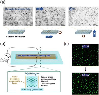 | ||
| Fig. 12 (a) Alignments of magnetized NH2-MIL-53(Al) depending on the direction of the magnetic field. Adapted with permission from ref. 92. Copyright 2017, Wiley-VCH. (b) Setup of a capillary cell and (c) alignments of NU-1000Si affected by the electric field. Adapted with permission from ref. 93. Copyright 2019, American Chemical Society. | ||
An electric field can also assist in the dynamic alignment of anisotropic MOF particles at random positions, similar to the magnetic field. NU-1000 crystals functionalized with trimethoxy(octadecyl)silane (TMODS) (NU-1000Si) were dispersed in bromobenzene.93 The pyrene-based ligand in NU-1000Si serves as a fluorophore, allowing for measurements of dynamic particle alignment through confocal microscopy without the need for additional dye functionalization. The suspension of NU-1000Si was filled within a capillary cell and exposed to an alternating current (AC) electric field (Fig. 12b). Consequently, the NU-1000Si particles aligned themselves along the direction of the electric field and maintained their positions without aggregation. The alignment of the particles exhibits a periodic pattern corresponding to the on/off cycles of the electric field confirmed by confocal images. Researchers have attributed the alignment phenomenon to the presence of ions in the channels of NU-1000 and the formation of an electrical double layer. In a subsequent study of the same group, superstructures of anisotropic MOFs (namely NU-1000, MIL-53-NH2(Al), and MIL-68(In)) with long-ranged orientational order were obtained through the precise manipulation of alignment of MOF crystals by applying an electric field, followed by a sedimentation process.94
To achieve a well-defined architecture, it is crucial to prepare MOFs with precisely defined flat facets. External forces can then be applied to assemble the desired structure. Yanai et al. reported an one-dimensional (1D) homogeneous MOF chain under an electric field with uniform and micro-sized ZIF-8 crystals.95 The crystals were dispersed in ethylene glycol to be placed between indium tin oxide (ITO)-coated coverslips and then subjected to an electric field. Under the electric field, rhombic dodecahedral ZIF-8 crystals aligned in the [110] direction and adhered to each other using their (110) planes, forming a 1D chain with maximized dipole–dipole interactions (Fig. 13a and b). This chain structure remained stable at a low frequency (1 kHz) but not at a high frequency (1 MHz). Truncated rhombic dodecahedral ZIF-8 crystals also formed 1D chains, with some crystals attached to both the (110) and (100) planes because of their similar plane sizes. However, for truncated cubic ZIF-8 crystals, they aligned in the [100] direction and attached to the (100) planes under the electric field (Fig. 13c). The 1D chain structure was not maintained after the electric field was turned off, likely due to the convex nature of the (100) planes, which resulted in weaker van der Waals attraction.
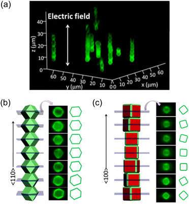 | ||
| Fig. 13 (a) In situ confocal microscope observations of rhombic dodecahedral ZIF-8 particles assembled into a homogeneous 1D chain under the influence of a 1 MHz electric field. Scheme of 1D chains composed of (b) rhombic dodecahedral ZIF-8 particles with the (110) planes in contact and (c) truncated cubic ZIF-8 particles with the (100) planes in contact, along with confocal images of cross-sectional ZIF-8 particles within the 1D chains. Adapted with permission from ref. 95. Copyright 2013, American Chemical Society. | ||
4. Alignment of MOF crystals in a monolayer
Aligning MOF particles in two dimensions within a bulk medium poses challenges due to the multidirectional applied alignment forces and high particle mobility. However, at the interface of synthetic media, the spatial constraint allows for the formation of a monolayer consisting of pre-formed MOF crystals. The interfacial interaction plays a crucial role in determining the particle orientation in this 2D architecture.96–98 Nonetheless, studying oriented MOF particles in two dimensions is challenging due to the limited interactions that preserve and transfer the aligned particles onto other substrates. To address this limitation, the introduction of surfactants or polymers has been implemented to fix particle orientation.99–102 This advancement enhances the versatility of the resulting 2D architecture, allowing for repeated deposition on substrates and the creation of practical freestanding films.Tsotsalas et al. achieved a significant breakthrough in creating aligned MOF monolayers using air–liquid assembly and Langmuir-Blodgettry techniques.103 They fabricated diverse MOFs, including octahedral HKUST-1, cubic HKUST-1, hexagonal prismatic [Al12O(OH)18(H2O)3(Al2(OH)4)(BTC)6]n, and platy [Cu2(BDC)2(bpy)]n (BTC: benzene-1,3,5-tricarboxylate; bpy: 4,4′-bipyridine), into a monolayer, respectively. The MOFs were suspended in methanol and cast onto a water surface, followed by dense compression. The resulting monolayers were transferred onto various substrates via dip coating. The films exhibited structural integrity even when freestanding on a Cu grid. Throughout film formation, the specific facets of the MOFs were oriented, as confirmed by out-of-plane XRD analysis. Specifically, octahedral HKUST-1, cubic HKUST-1, [Al12O(OH)18(H2O)3(Al2(OH)4)(BTC)6]n, and [Cu2(BDC)2(bpy)]n were oriented along their [111], [100], [100], and [001] directions, respectively, in the out-of-plane direction of the substrate (Fig. 14).
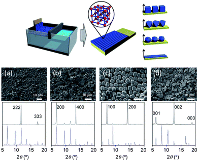 | ||
| Fig. 14 Scheme of the formation of oriented MOF layers by Langmuir-Blodgettry. SEM images and corresponding out-of-plane XRD patterns of (a) octahedral HKUST-1, (b) cubic HKUST-1, (c) [Al12O(OH)18(H2O)3(Al2(OH)4)(BTC)6]n, and (d) [Cu2(BDC)2(bpy)]n. Adapted with permission from ref. 103. Copyright 2012, Royal Society of Chemistry. | ||
In the absence of a compression equipment, Lu et al. demonstrated the creation of an aligned monolayer using surface tension principles.99 They synthesized UiO-66 crystals with distinct octahedral morphologies by incorporating acetic acid as a modulator. Surface modification with polyvinylpyrrolidone (PVP) enhanced crystal stability and enabled dispersion in an ethanol/water solvent. Subsequently, the crystal suspension was carefully cast onto water, resulting in the spreading of the crystals by the surface tension gradient. To further consolidate the crystals and achieve a densely packed monolayer, they introduced a small quantity of sodium dodecyl sulfate (SDS) solution, and the resulting monolayer could be transferred onto various substrates (Fig. 15). XRD and SEM analysis of the monolayer confirmed the alignment of the UiO-66 crystals in the (111) plane parallel to the substrate.
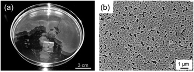 | ||
| Fig. 15 (a) Photograph and (b) SEM image of aligned 2D monolayer of PVP modified UiO-66 crystals after introduction of SDS solution. Reproduced from ref. 99. Copyright 2013, Wiley-VCH. | ||
The control of polyhedral nanoparticle orientation at the water-solvent interface is typically achieved by manipulating the interfacial tension between the nanoparticles and the liquid phase. This control can be achieved by modifying the nanoparticle surface or changing to solvents with different interfacial tensions, but most studies have focused on the former because it is easier to maintain alignment during substrate transfer. The Cohen group reported a simple one-step method for controlling the 2D alignment of polyhedral MOF particles by changing the casting solvent and immobilizing the oriented particles in large-area polymer films (Fig. 16a).101 A sticky thermocurable PDMS oligomer embedded in the casting solvent played a key role in preserving and fixing the MOF orientation. Two types of MOF particles, the hexagonal bifrustum form of MIL-96 and octahedral form of the UiO-66 family, were selected and suspended in a casting solvent containing PDMS. When the casting solvent was introduced onto the water surface, it spread on the water surface and evaporated, resulting in an aligned MOF-PDMS film. Notably, the MOF orientation differed based on the casting solvent used, a phenomenon tied to the casting solvent's interfacial tension. For MIL-96, butanol with low interfacial tension exposed the (102) and (h0l) planes, while CHCl3 with high interfacial tension exposed the (200) plane (Fig. 16b). For UiO-66, the (111) and (200) planes are mainly exposed when butanol and CHCl3 are used as the casting solvents, respectively (Fig. 16c). After thermal curing, the oriented MOFs were fixed in the PDMS film and could be transferred to various substrates such as glass, polymer, and foil.
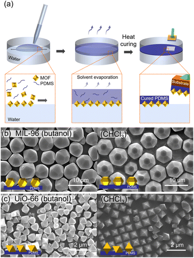 | ||
| Fig. 16 (a) Scheme of preparation of oriented MOF-PDMS films. (b) SEM images of oriented (b) MIL-96-PDMS films and (c) UiO-66-PDMS films prepared using butanol (left) and CHCl3 (right) as a casting solvent. Adapted with permission from ref. 101. Copyright 2021, American Chemical Society. | ||
5. Alignment of MOF crystals via assembly
In pre-formed polyhedral MOF particles, when specific facets align and join with those of neighboring particles, they ultimately unveil identical facets in a particular direction, resulting in an oriented structure.50,104 Consequently, the driving forces of colloidal self-assembly proved to be highly effective in the creation of novel-oriented MOF structures.The depletion interactions induced by non-adsorbing small molecules promote attractive forces between larger colloids. This drives shape-oriented assembly by encouraging face-to-face contact to maximize the entropy in polyhedral colloids. While the depletion force has been used in various colloid systems, its application to MOF colloids has rarely been studied owing to their special properties, such as low surface charges and exposed coordination sites, which hinder the equilibrium assembly. By introducing ionic amphiphiles into MOF particles to enhance the depletion interaction, Lyu et al. successfully assembled a broad range of MOF particles into low-dimensional assemblies including 1D linear straight and alternating or bundled chains (Fig. 17a).105 In their experiments, the ZIF-8 particles were coated with cetyltrimethylammonium chloride (CTAC) to ensure consistent zeta potentials. The particles were dispersed in a dilute CTAC solution and transferred to glass capillary tubes to induce particle assembly through depletion forces. Rhombic dodecahedral ZIF-8 particles formed 1D chains on a smooth substrate, with the (110) facets adhering to each other. Truncated rhombic dodecahedral ZIF-8 particles also assembled into 1D chains (Fig. 17b). Increasing the concentration of ZIF-8 particles led to the formation of bundled 1D chain structures as crosslinker particles filled the gaps between the (110) planes. Similarly, MIL-88A and UiO-66 particles were coated with SDS and CTAC, respectively, and assembled through depletion forces. MIL-88A formed a 1D alternating chain structure on a smooth substrate (Fig. 17c), while UiO-66 formed a quasi-1D striped structure on a rough substrate.
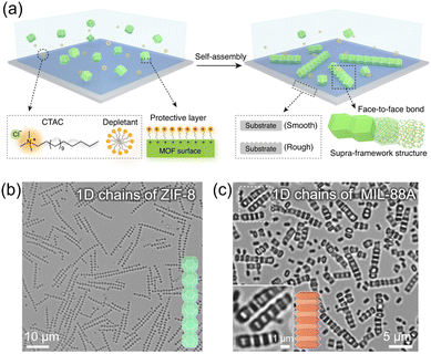 | ||
| Fig. 17 (a) Scheme of 1D chain assembly by depletion interactions. Optical images of 1D chains of (b) ZIF-8, and (c) MIL-88A. Adapted with permission from ref. 105. Copyright 2022, Springer Nature. | ||
Perfectly oriented 1D chains of MOFs can be created by exploiting crystal engineering techniques and the unique liquid bridge for specific facets of MOFs (Fig. 18a). Lyu et al. achieved 1D chains of MOFs by growing UiO-66 on MIL-96 through epitaxial growth based on crystal engineering principles.106 The resulting MIL-96 modules had UiO-66 patches. To construct the 1D chains, a liquid glue consisting of 3-(trimethoxysilyl)propyl methacrylate oligomer (o-TPM) was utilized. The difference in zeta potential between MIL-96 and UiO-66 caused the TPM oligomer to selectively attach to the UiO-66 patch. Using an o-TPM layer as an adhesive, the “sticky” UiO-66 patches in neighboring modules were able to bind together, driven by a strong capillary force that maximized the contact between the flat patches. The liquid bridge played a crucial role in providing a strong and reconfigurable capillary force, resulting in the formation of precise directional 1D chain structures with unprecedented control over the position, rotation, and orientation of the building blocks (Fig. 18b). Furthermore, these perfectly oriented 1D chains were fixed through the polymerization of the liquid bridges.
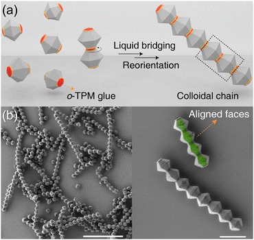 | ||
| Fig. 18 (a) Scheme of the formation of a heterogeneous 1D chain through liquid bridging of TPM oligomers between UiO-66 patches on MIL-96 modules. (b and c) SEM images of the 1D chains composed of MIL-96 modules with UiO-66 patches at different magnification. Adapted with permission from ref. 106. Copyright 2022, Wiley-VCH. | ||
In 2012, Yanai et al. reported oriented 2D assemblies of MOF particles through the controlled evaporation of colloidal solutions containing rhombic dodecahedral ZIF-8 particles (Fig. 19a).107 While drying ZIF-8 colloidal solutions on a Si wafer, evaporation from methanol and isopropyl alcohol dispersions did not yield ordered structures. On the other hand, drying a colloidal N,N-dimethylformamide (DMF) solution containing 1 wt% of ZIF-8 at 60 °C resulted in closely packed hexagonal arrangements of ZIF-8 crystals oriented in the 〈111〉 direction (Fig. 19b), due to prolonged evaporation allowing particle rearrangement for stability. Lowering the ZIF-8 concentration to 0.05 wt% revealed a monolayer having hexagonal arrangement with 〈110〉 crystal orientation, which was attributed to the dominant capillary force between the particle and the substrate.
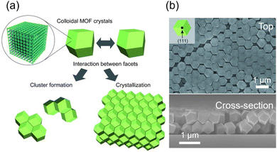 | ||
| Fig. 19 (a) Scheme of the interaction between ZIF-8 crystal facets driven by capillary forces and van der Waals interactions. (b) SEM images of top view (top) and cross-sectional view (down) of assembled ZIF-8 particles in 〈111〉 direction parallel to the out-of-plane direction of Si substrates. Adapted with permission from ref. 107. Copyright 2012, Wiley-VCH. | ||
The precise assembly of MOF particles into a 3D architecture presents challenges due to the low surface charge of MOF particles and the presence of exposed active sites that interact with guest molecules, hindering interparticle interactions. Coating MOF particles with polymers and surfactants can overcome these limitations and create an environment where depletion forces can induce particle assembly.99,108,109 This approach has been explored in the literature and has resulted in the formation of unique 3D architectures with distinct properties, such as photonic crystals and unique optical properties, making them highly promising for various applications.108,109
PVP-modified UiO-66 was successfully oriented into a 2D architecture using surface tension. Building upon this, Lu et al. stacked multiple layers of the 2D architecture to create a 3D structure of PVP-modified UiO-66.99 The orientation of the (111) plane was maintained even after sedimentation, and a single-step sedimentation process in a vertically positioned glass pipette further enhanced the structural integrity of the crystals. Maspoch group assembled CTAB-coated (CTAB: cetyltrimethylammonium bromide) truncated rhombic dodecahedral (TRD) ZIF-8 crystals into a 3D architecture using depletion forces.108 Droplets of an aqueous suspension containing the TRD ZIF-8 particles were placed on a glass surface, and water evaporation at 65 °C facilitated the assembly. The resulting 3D architecture exhibited a rhombohedral packing arrangement, with six particles aligned through the adhesion of their (100) planes and another six particles aligned through the adhesion of their (110) planes (Fig. 20a and b). The packing arrangement depended on the truncation value (t) of the ZIF-8 particle, with a rhombohedral packing observed for t > 0.66 and a face-centered cubic (fcc) packing for t < 0.66. UiO-66 particles also formed a 3D architecture with a Minkowski lattice structure under similar assembly conditions but at a water evaporation temperature of 85 °C. Further research conducted by the same group focused on controlling the alignment of TRD ZIF-8 (t = 0.63) in a 3D architecture by adjusting the concentration of CTAB in stock solution.109 At CTAB concentrations of 1 or 2 mg mL−1, the ZIF-8 crystals oriented with their [111] direction within the architecture (Fig. 20c). At a concentration of 3 mg mL−1, the crystals were oriented in the [100] direction (Fig. 20d). At a concentration of 4 mg mL−1, the resulting architectures predominantly exhibited [110]-oriented ZIF-8 crystals with a few [100]-oriented crystals (Fig. 20e). Similar trends were observed when using SDS instead of CTAB, supporting the hypothesis that the outcomes were influenced by the repulsive forces and surface tension during the assembly process.
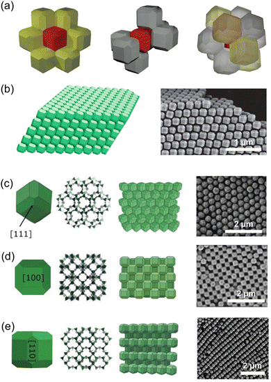 | ||
| Fig. 20 (a) Scheme for adjacent truncated rhombic dodecahedral (TRD) ZIF-8 particles for representing connectivity; six TRD particles adhered to a central particle with (110) facets (left), six particles with (100) facets (middle), resulting in twelve particles adhered to the central particle (right). (b) Scheme (left) and SEM image (right) of ZIF-8 superstructure formed through this connectivity. Adapted with permission from ref. 108. Copyright 2018, Springer Nature. The morphology scheme depicting the exposed plane of TRD ZIF-8 particles along with the corresponding crystallographic plane and scheme of packing in ZIF-8 superstructure along with the corresponding SEM image in the (c) [111] (first row), (d) [100] (second row), and (e) [110] (third row) oriented cases. Adapted with permission from ref. 109. Copyright 2019, Wiley-VCH. | ||
6. Conclusion
MOFs are versatile crystalline materials with diverse applications in various fields. One promising approach for customizing MOFs without post-synthetic modification or novel structural design is to exploit the anisotropic nature of MOFs, where the properties depend on specific crystal facets. By orienting MOF crystals, specific facets can be selectively exposed, resulting in enhanced characteristics such as permeability, selectivity, and conductivity. As a result, there has been increasing interest in the synthesis of oriented MOFs, and various strategies based on different orientation mechanisms have been extensively studied.There are two main approaches to achieve oriented MOFs. The first involves direct growth on substrates, where precursor molecules are adsorbed onto the substrate, guiding the growth based on factors like substrate lattice parameters and surface interactions. This approach allows for tailored structures and novel architectures when integrated with other substrates. The second approach utilizes external forces, such as electric and magnetic fields, interfacial tension, and capillary and depletion forces, to align pre-formed MOF crystals. Using pre-formed crystals provides flexibility in material selection and enables the fabrication of highly ordered orientations on a large scale. In particular, the exposure of crystal plane can be varied even in the same MOF structures by controlling crystal morphology with various MOF synthetic strategies,107,108,110 which could further enrich the number of crystallographic orientations of MOFs that can be aligned over large areas. Self-assembly of polyhedral MOF particles with distinct facets leads to the formation of oriented structures, fully utilizing their directional anisotropic properties over a large area. The precise arrangement of pre-formed MOF crystals enhances their functionalities and expands their applications.
There are challenges that need to be addressed in future research on MOF orientation. First, achieving precise and complete orientation of MOF particles within desired structures is a primary challenge. While there have been few reports of fully oriented MOF superstructures, most research has focused on achieving orientation in a single direction. Second, developing generally applicable orientation strategies for various MOFs based on the understanding of mechanism behind orientations is crucial. Third, understanding how different orientations impact the performance of MOFs is another important aspect. Especially, investigating the relationship between orientation and properties such as catalytic activity, gas adsorption, and electrical conductivity is essential for optimizing MOF-based materials. Last, for practical applications, scalability, stability, and cost-effectiveness must be considered. Developing fabrication methods that can be applied at a larger scale and demonstrating the performance of oriented MOFs in real-world applications are necessary steps for commercialization.
In summary, research on MOF particle orientation holds great promise for advancing the field of porous materials. By precisely controlling the orientation of MOFs, their functionalities can be enhanced, leading to improved performance and expanded applications. Overcoming the challenges in achieving precise orientation and further exploring the relationships between orientation and properties will pave the way for practical implementation and widespread use of oriented MOFs in various industries.
Conflicts of interest
There are no conflicts to declare.Acknowledgements
J. Park and H. R. Moon acknowledge that this work was supported by a National Research Foundation of Korea (NRF) grant funded by the Korea government (MSIT) (No. NRF-2020R1A2C3008908 and NRF-2019M3E6A1103980). J. Y. Kim was supported by the NRF funded by the Korea government (NRF-2022R1C1C101022012).Notes and references
- O. M. Yaghi, M. O’Keeffe, N. W. Ockwig, H. K. Chae, M. Eddaoudi and J. Kim, Reticular synthesis and the design of new materials, Nature, 2003, 423, 705–714 CrossRef CAS PubMed.
- S. L. James, Metal–organic frameworks, Chem. Soc. Rev., 2003, 32, 276–288 RSC.
- S. Kitagawa, R. Kitaura and S.-I. Noro, Functional porous coordination polymers, Angew. Chem., Int. Ed., 2004, 43, 2334–2375 CrossRef CAS PubMed.
- H.-L. Jiang and Q. Xu, Porous metal–organic frameworks as platforms for functional applications, Chem. Commun., 2011, 47, 3351–3370 RSC.
- W. Xuan, C. Zhu, Y. Liu and Y. Cui, Mesoporous metal–organic framework materials, Chem. Soc. Rev., 2012, 41, 1677–1695 RSC.
- H. Furukawa, K. E. Cordova, M. O’Keeffe and O. M. Yaghi, The chemistry and applications of metal–organic frameworks, Science, 2013, 341, 1230444 CrossRef PubMed.
- H.-C. Zhou and S. Kitagawa, Metal–organic frameworks (MOFs), Chem. Soc. Rev., 2014, 43, 5415–5418 RSC.
- J.-R. Li, R. J. Kuppler and H.-C. Zhou, Selective gas adsorption and separation in metal–organic frameworks, Chem. Soc. Rev., 2009, 38, 1477–1504 RSC.
- D. K. Yoo, H. C. Woo and S. H. Jhung, Removal of particulate matter with metal–organic framework-incorporated materials, Coord. Chem. Rev., 2020, 422, 213477 CrossRef CAS.
- T. Wang, E. Lin, Y.-L. Peng, Y. Chen, P. Cheng and Z. Zhang, Rational design and synthesis of ultramicroporous metal–organic frameworks for gas separation, Coord. Chem. Rev., 2020, 423, 213485 CrossRef CAS.
- E. Jin, S. Lee, E. Kang, Y. Kim and W. Choe, Metal–organic frameworks as advanced adsorbents for pharmaceutical and personal care products, Coord. Chem. Rev., 2020, 425, 213526 CrossRef CAS.
- J. Y. Kim, R. Balderas-Xicohtencatl, L. Zhang, S. G. Kang, M. Hirscher, H. Oh and H. R. Moon, Exploiting diffusion barrier and chemical affinity of metal–organic frameworks for efficient hydrogen isotope separation, J. Am. Chem. Soc., 2017, 139, 15135–15141 CrossRef CAS PubMed.
- J. Y. Kim, L. Zhang, R. Balderas-Xicohtencatl, J. Park, M. Hirscher, H. R. Moon and H. Oh, Selective hydrogen isotope separation via breathing transition in MIL-53(Al), J. Am. Chem. Soc., 2017, 139, 17743–17746 CrossRef CAS PubMed.
- J. Y. Kim, J. Park, J. Ha, M. Jung, D. Wallacher, A. Franz, R. Balderas-Xicohtencatl, M. Hirscher, S. G. Kang, J. T. Park, I. H. Oh, H. R. Moon and H. Oh, Specific isotope-responsive breathing transition in flexible metal–organic frameworks, J. Am. Chem. Soc., 2020, 142(31), 13278–13282 CrossRef CAS PubMed.
- J. Ha, M. Jung, J. Park, H. Oh and H. R. Moon, Thermodynamic separation of hydrogen isotopes using Hofmann-type metal–organic frameworks with high-density open metal sites, ACS Appl. Mater. Interfaces, 2022, 14(27), 30946–30951 CrossRef CAS PubMed.
- H. B. Son, S. Cho, K. Baek, J. Jung, S. Nam, D.-Y. Han, S. J. Kang, H. R. Moon and S. Park, All-impurities scavenging, safe separators with functional metal–organic-frameworks for high-energy-density Li-ion battery, Adv. Funct. Mater., 2023, 2302563 CrossRef.
- J. L. C. Rowsell and O. M. Yaghi, Strategies for hydrogen storage in metal–organic frameworks, Angew. Chem., Int. Ed., 2005, 44, 4670–4679 CrossRef CAS PubMed.
- A. U. Czaja, N. Trukhan and U. Müller, Industrial applications of metal–organic frameworks, Chem. Soc. Rev., 2009, 38, 1284–1293 RSC.
- S. Ma and H.-C. Zhou, Gas storage in porous metal–organic frameworks for clean energy applications, Chem. Commun., 2010, 46, 44–53 RSC.
- M. P. Suh, H. J. Park, T. K. Prasad and D.-W. Lim, Hydrogen storage in metal–organic frameworks, Chem. Rev., 2012, 112, 782–835 CrossRef CAS PubMed.
- J. Lee, O. K. Farha, J. Roberts, K. A. Scheidt, S. T. Nguyen and J. T. Hupp, Metal–organic framework materials as catalysts, Chem. Soc. Rev., 2009, 38, 1450–1459 RSC.
- A. Corma, H. García and F. X. Llabrés i Xamena, Engineering metal organic frameworks for heterogeneous catalysis, Chem. Rev., 2010, 110(8), 4606–4655 CrossRef CAS PubMed.
- Y. Liu, D. Huang, M. Cheng, Z. Liu, C. Lai, C. Zhang, C. Zhou, W. Xiong, L. Qin, B. Shao and Q. Liang, Metal sulfide/MOF-based composites as visible-light-driven photocatalysts for enhanced hydrogen production from water splitting, Coord. Chem. Rev., 2020, 409, 213220 CrossRef CAS.
- A. Bavykina, N. Kolobov, I. S. Khan, J. A. Bau, A. Ramirez and J. Gascon, Metal–organic frameworks in heterogeneous catalysis: recent progress, new trends, and future perspectives, Chem. Rev., 2020, 120, 8468–8535 CrossRef CAS PubMed.
- D.-D. Ma and Q.-L. Zhu, MOF-based atomically dispersed metal catalysts: recent progress towards novel atomic configurations and electrocatalytic applications, Coord. Chem. Rev., 2020, 422, 213483 CrossRef CAS.
- A. Alzamly, M. Bakiro, S. H. Ahmed, M. A. Alnaqbi and H. L. Nguyen, Rare-earth metal–organic frameworks as advanced catalytic platforms for organic synthesis, Coord. Chem. Rev., 2020, 425, 213543 CrossRef CAS.
- M. D. Allendorf, C. A. Bauer, R. K. Bhakta and R. J. T. Houk, Luminescent metal–organic frameworks, Chem. Soc. Rev., 2009, 38, 1330–1352 RSC.
- Y. Cui, Y. Yue, G. Qian and B. Chen, Luminescent functional metal–organic frameworks, Chem. Rev., 2012, 112, 1126–1162 CrossRef CAS PubMed.
- Y. Cui, B. Chena and G. Qian, Lanthanide metal–organic frameworks for luminescent sensing and light-emitting applications, Coord. Chem. Rev., 2014, 273–274, 76–86 CrossRef CAS.
- L. E. Kreno, K. Leong, O. K. Farha, M. Allendorf, R. P. Van Duyne and J. T. Hupp, Metal–organic framework materials as chemical sensors, Chem. Rev., 2012, 112, 1105–1125 CrossRef CAS PubMed.
- Z. Hu, B. J. Deibert and J. Li, Luminescent metal–organic frameworks for chemical sensing and explosive detection, Chem. Soc. Rev., 2014, 43, 5815–5840 RSC.
- D. J. Wales, J. Grand, V. P. Ting, R. D. Burke, K. J. Edler, C. R. Bowen, S. Mintova and A. D. Burrows, Gas sensing using porous materials for automotive applications, Chem. Soc. Rev., 2015, 44, 4290–4321 RSC.
- H.-Y. Li, S.-N. Zhao, S.-Q. Zang and J. Li, Functional metal–organic frameworks as effective sensors of gases and volatile compounds, Chem. Soc. Rev., 2020, 49, 6364–6401 RSC.
- S. Cho, C. Park, M. Jeon, J. H. Lee, O. Kwon, S. Seong, J. Kim, I.-D. Kim and H. R. Moon, Interface-sensitized chemiresistor: integrated conductive and porous metal–organic frameworks, Chem. Eng. J., 2022, 449, 137780 CrossRef CAS.
- D. Nam, J. Kim and W. Choe, Evolution of Zr nodes in metal–organic frameworks, Trends Chem., 2023, 5(5), 339–352 CrossRef CAS.
- A. E. Baumann, D. A. Burns, B. Liu and V. S. Thoi, Metal–organic framework functionalization and design strategies for advanced electrochemical energy storage devices, Commun. Chem., 2019, 2, 86 CrossRef.
- H. D. Lawson, S. P. Walton and C. Chan, Metal–organic frameworks for drug delivery: a design perspective, ACS Appl. Mater. Interfaces, 2021, 13(6), 7004–7020 CrossRef CAS PubMed.
- M. Kim, J. Yi, S.-H. Park and S. S. Park, Heterogenization of molecular electrocatalytic active sites through reticular chemistry, Adv. Mater., 2023, 35, 2203791 CrossRef CAS PubMed.
- S. C. Ward and G. Sadiq, Introduction to the Cambridge Structural Database – a wealth of knowledge gained from a million structures, CrystEngComm, 2020, 22, 7143–7144 RSC.
- Z. Wang and S. M. Cohen, Postsynthetic modification of metal–organic frameworks, Chem. Soc. Rev., 2009, 38, 1315–1329 RSC.
- S. M. Cohen, Postsynthetic methods for the functionalization of metal–organic frameworks, Chem. Rev., 2012, 112(2), 970–1000 CrossRef CAS PubMed.
- M. Lalonde, W. Bury, O. Karagiaridi, Z. Brown, J. T. Hupp and O. K. Farha, Transmetalation: routes to metal exchange within metal–organic frameworks, J. Mater. Chem. A, 2013, 1, 5453–5468 RSC.
- C. K. Brozek and M. Dinca, Cation exchange at the secondary building units of metal–organic frameworks, Chem. Soc. Rev., 2014, 43, 5456–5467 RSC.
- J. D. Evans, C. J. Sumby and C. J. Doonan, Post-synthetic metalation of metal–organic frameworks, Chem. Soc. Rev., 2014, 43, 5933–5951 RSC.
- X. Song, T. K. Kim, H. Kim, D. Kim, S. Jeong, H. R. Moon and M. S. Lah, Post-synthetic modifications of framework metal ions in isostructural metal–organic frameworks: core–shell heterostructures via selective transmetalations, Chem. Mater., 2012, 24(15), 3065–3073 CrossRef CAS.
- S. Jeong, J. Seong, S. W. Moon, J. Lim, S. B. Baek, S. K. Min and M. S. Lah, Spatial distribution modulation of mixed building blocks in metal–organic frameworks, Nat. Commun., 2022, 13, 1027 CrossRef CAS PubMed.
- D. Kim, H. Yoo, K. Kim, D. Kim, K. T. Kim, C. Kim, J. Y. Kim, H. R. Moon and M. Kim, Post-synthetic ligand cyclization in metal– organic frameworks through functional group connection with regioisomerism, Chem. Commun., 2022, 58, 5948–5951 RSC.
- Q.-L. Zhua and Q. Xu, Metal–organic framework composites, Chem. Soc. Rev., 2014, 43, 5468–5512 RSC.
- I. E. Khalil, J. Fonseca, M. R. Reithofer, T. Eder and J. M. Chin, Tackling orientation of metal–organic frameworks (MOFs): the quest to enhance MOF performance, Coord. Chem. Rev., 2023, 481, 215043 CrossRef CAS.
- J. Fonseca, L. Meng, I. Imaz and D. Maspoch, Self-assembly of colloidal metal–organic framework (MOF) particles, Chem. Soc. Rev., 2023, 52, 2528–2543 RSC.
- M. Takahashi, Oriented films of metal–organic frameworks on metal hydroxides via heteroepitaxial growth, Bull. Chem. Soc. Jpn., 2021, 94, 2602–2612 CrossRef CAS.
- A. Bétard and R. A. Fischer, Metal–organic framework thin films: from fundamentals to applications, Chem. Rev., 2012, 112, 1055–1083 CrossRef PubMed.
- Q. Ma, T. Zhang and B. Wang, Shaping of metal–organic frameworks, a critical step toward industrial applications, Matter, 2022, 5, 1070–1091 CrossRef CAS.
- A. van der Drift, Evolutionary selection, a principle governing growth orientation in vapour-deposited layers, Philips Res. Repts., 1967, 22, 267–288 CAS.
- J. Cho and Y. Ishida, Macroscopically oriented porous materials with periodic ordered structures: from zeolites and metal–organic frameworks to liquid-crystal-templated mesoporous materials, Adv. Mater., 2017, 29, 1605974 CrossRef PubMed.
- H. Bux, A. Feldhoff, J. Cravillon, M. Wiebcke, Y.-S. Li and J. Caro, Oriented zeolitic imidazolate frameowrks-8 membrane with sharp H2/C3H8 molecular sieve separation, Chem. Mater., 2011, 23, 2262–2269 CrossRef CAS.
- Y. Sun, Y. Liu, J. Caro, X. Guo, C. Song and Y. Liu, In-plane epitaxial growth of highly c-oriented NH2-MIL-125(Ti) membranes with superior H2/CO2 selectivity, Angew. Chem., Int. Ed., 2018, 57, 16088–16093 CrossRef CAS PubMed.
- T. Ohata, A. Nomoto, T. Watanabe, I. Hirosawa, T. Makita, J. Takeya and R. Makiura, Uniaxially oriented electrically conductive metal−organic framework nanosheets assembled at air/liquid interfaces, ACS Appl. Mater. Interfaces, 2021, 13, 54570–54578 CrossRef CAS PubMed.
- L. Yang, G. Zhu, H. Wen, X. Guan, X. Sun, H. Feng, W. Tian, D. Zheng, X. Cheng and Y. Yao, Constructing a highly oriented layered MOF nanoarray from a layered double hydroxide for efficient and long-lasting alkaline water oxidation electrocatalysis, J. Mater. Chem. A, 2019, 7, 8771–8776 RSC.
- Z. Xu, C.-L. Yeh, Y. Jiang, X. Yun, C.-T. Li, K.-C. Ho, J. T. Lin and R. Y.-Y. Lin, Orientation-adjustable metal–organic framework nanorods for efficient oxygen evolution reaction, ACS Appl. Mater. Interfaces, 2021, 13(24), 28242–28251 CrossRef CAS PubMed.
- K. Okada, K. Mori, A. Fukatsu and M. Takahashi, Oriented growth of semiconducting TCNQ@Cu3(BTC)2 MOF on Cu(OH)2: crystallographic orientation and pattern formation toward semiconducting thin-film devices, J. Mater. Chem. A, 2021, 9, 19613–19618 RSC.
- S. Goswami, I. Hod, J. D. Duan, C.-W. Kung, M. Rimoldi, C. D. Malliakas, R. H. Palmer, O. K. Farha and J. T. Hupp, Anisotropic redox conductivity within a metal–organic framework material, J. Am. Chem. Soc., 2019, 141, 17696–17702 CrossRef CAS PubMed.
- J. Ha and H. R. Moon, Synthesis of MOF-on-MOF architectures in the context of interfacial lattice matching, CrystEngComm, 2021, 23, 2337–2354 RSC.
- D. H. Hong, H. S. Shim, J. Ha and H. R. Moon, MOF-on-MOF architectures: applications in separation, catalysis, and sensing, Bull. Korean Chem. Soc, 2021, 42, 956–969 CrossRef CAS.
- C. Liu, J. Wang, J. Wan and C. Yu, MOF-on-MOF hybrids: synthesis and applications, Coord. Chem. Rev., 2021, 432, 213743 CrossRef CAS.
- Z.-G. Gu and J. Zhang, Epitaxial growth and applications of oriented metal–organic framework thin films, Coord. Chem. Rev., 2019, 378, 513–532 CrossRef CAS.
- S. Wang, J. Liu, B. Pulido, Y. Li, D. Mahalingam and S. P. Nunes, Oriented zeolitic imidazolate framework (ZIF) nanocrystal films for molecular separation membranes, ACS Appl. Nano Mater., 2020, 3, 3839–3846 CrossRef CAS.
- Q. Hou, S. Zhou, Y. Wei, J. Caro and H. Wang, Balancing the grain boundary structure and the framework flexibility through bimetallic metal−organic framework (MOF) membranes for gas separation, J. Am. Chem. Soc., 2020, 142(21), 9582–9586 CAS.
- P. Malik and R. Haldar, Accessing accelerated molecular diffusion by nanopore alignment in a MOF thin film, Mol. Syst. Des. Eng., 2022, 7, 873–877 RSC.
- R. Xu, Y. Kang, W. Zhang, X. Zhang and B. Pan, Oriented UiO-67 metal–organic framework membrane with fast and selective lithium-ion transport, Angew. Chem., Int. Ed., 2022, 61, e202115443 CrossRef CAS PubMed.
- Y. Jiang, W. Danowski, B. L. Feringa and L. Heinke, Nanoporous films with oriented arrays of molecular motors for photoswitching the guest adsorption and diffusion, Angew. Chem., Int. Ed., 2023, 62, e202214202 CrossRef CAS PubMed.
- Y. Liu, G. Zeng, Y. Pan and Z. Lai, Synthesis of highly c-oriented ZIF-69 membranes by secondary growth and their gas permeation properties, J. Membr. Sci., 2011, 379, 46–51 CrossRef CAS.
- S. Chen, Y. Sun, S. Chen, Y. Gao, F. Wang, H. Li and Y. Liu, Facile fabrication of a highly (110)-oriented ZIF-7 film with rod-shaped seeds, Chem. Commun., 2021, 57, 2128–2131 RSC.
- P. Falcaro, K. Okada, T. Hara, K. Ikigaki, Y. Tokudome, A. W. Thornton, A. J. Hill, T. Williams, C. Doonan and M. Takahashi, Centimetre-scale micropore alignment in oriented polycrystalline metal–organic framework films via heteroepitaxial growth, Nat. Mater., 2017, 16, 342–348 CrossRef CAS PubMed.
- M. J. Velásquez-Hernández, M. Linares-Moreau, L. A. Brandner, B. Marmiroli, M. Barella, G. P. Acuna, S. Dal Zilio, M. F. K. Verstreken, D. E. Kravchenko, O. M. Linder-Patton, J. D. Evans, H. Wiltsche, F. Carraro, H. Wolinski, R. Ameloot, C. Doonan and P. Falcaro, Fabrication of 3D oriented MOF micropatterns with anisotropic fluorescent properties, Adv. Mater., 2023, 35, 2211478 CrossRef PubMed.
- M. Singh, N. Kaura and E. Comini, The role of self-assembled monolayers in electronic devices, J. Mater. Chem. C, 2020, 8, 3938–3955 RSC.
- I. Stassen, N. Burtch, A. Talin, P. Falcaro, M. Allendorf and R. Ameloot, An updated roadmap for the integration of metal–organic frameworks with electronic devices and chemical sensors, Chem. Soc. Rev., 2017, 46, 3185–3241 RSC.
- E. Biemmi, C. Scherb and T. Bein, Oriented growth of the metal organic framework Cu3(BTC)2(H2O)3·xH2O tunable with functionalized self-assembled monolayers, J. Am. Chem. Soc., 2007, 129, 8054–8055 CrossRef CAS PubMed.
- C. Scherb, A. Schödel and T. Bein, Directing the structure of metal–organic frameworks by oriented surface growth on an organic monolayer, Angew. Chem., Int. Ed., 2008, 47, 5777–5779 CrossRef CAS PubMed.
- J.-L. Zhuang, M. Kind, C. M. Grytz, F. Farr, M. Diefenbach, S. Tussupbayev, M. C. Holthausen and A. Terfort, Insight into the oriented growth of surface-attached metal−organic frameworks: surface functionality, deposition temperature, and first layer order, J. Am. Chem. Soc., 2015, 137, 8237–8243 CrossRef CAS PubMed.
- Z. Wang, J. Liu, B. Lukose, Z. Gu, P. G. Weidler, H. Gliemann, T. Heine and C. Wöll, Nanoporous designer solids with huge lattice constant gradients: multiheteroepitaxy of metal–organic frameworks, Nano Lett., 2014, 14(3), 1526–1529 CrossRef CAS PubMed.
- C. Liu, X. Huang, J. Liu, J. Wang, Z. Chen, R. Luo, C. Wang, J. Li, L. Wang, J. Wan and C. Yu, A general approach to direct growth of oriented metal–organic framework nanosheets on reduced graphene oxides, Adv. Sci., 2020, 7, 1901480 CrossRef CAS PubMed.
- R. Makiura, S. Motoyama, Y. Umemura, H. Yamanaka, O. Sakata and H. Kitagawa, Surface nano-architecture of a metal– organic framework, Nat. Mater., 2010, 9, 565–571 CrossRef CAS PubMed.
- Z. Wang, L. S. Walter, M. Wang, P. St. Petkov, B. Liang, H. Qi, N. N. Nguyen, M. Hambsch, H. Zhong, M. Wang, S. Park, L. Renn, K. Watanabe, T. Taniguchi, S. C. B. Mannsfeld, T. Heine, U. Kaiser, S. Zhou, R. T. Weitz, X. Feng and R. Dong, Interfacial synthesis of layer-oriented 2D conjugated metal–organic framework films toward directional charge transport, J. Am. Chem. Soc., 2021, 143, 13624–13632 CrossRef CAS PubMed.
- Y.-S. Li, H. Bux, A. Feldhoff, G.-L. Li, W.-S. Yang and J. Caro, Controllable synthesis of metal–organic frameworks: from MOF nanorods to oriented MOF membranes, Adv. Mater., 2010, 22, 3322–3326 CrossRef CAS PubMed.
- C. Zhang, J. Yan, T. Ji, D. Du, Y. Sun, L. Liu, X. Zhang and Y. Liu, Fabrication of highly (110)-oriented ZIF-8 membrane at low temperature using nanosheet seed layer, J. Membr. Sci., 2022, 641, 119915 CrossRef CAS.
- E. Virmani, J. M. Rotter, A. Mahringer, T. von Zons, A. Godt, T. Bein, S. Wuttke and D. D. Medina, On-surface synthesis of highly oriented thin metal–organic framework films through vapor-assisted conversion, J. Am. Chem. Soc., 2018, 140, 4812–4819 CrossRef CAS PubMed.
- P. I. Scheurle, A. Mähringer, A. Biewald, A. Hartschuh, T. Bein and D. D. Medina, MOF-74(M) films obtained through vapor-assisted conversion—impact on crystal orientation and optical properties, Chem. Mater., 2021, 33(15), 5896–5904 CrossRef CAS.
- T. Stassin, S. Rodríguez-Hermida, B. Schrode, A. J. Cruz, F. Carraro, D. Kravchenko, V. Creemers, I. Stassen, T. Hauffman, D. De Vos, P. Falcaro, R. Resel and R. Ameloot, Vapour-phase deposition of oriented copper dicarboxylate metal–organic framework thin films, Chem. Commun., 2019, 55, 10056–10059 RSC.
- R. Ameloot, E. Gobechiya, H. Uji-i, J. A. Martens, J. Hofkens, L. Alaerts, B. F. Sels and D. E. De Vos, Direct patterning of oriented metal–organic framework crystals via control over crystallization kinetics in clear precursor solutions, Adv. Mater., 2010, 22, 2685–2688 CrossRef CAS PubMed.
- J.-L. Zhuang, D. Ar, X.-J. Yu, J.-X. Liu and A. Terfort, Patterned deposition of metal–organic frameworks onto plastic, paper, and textile substrates by inkjet printing of a precursor solution, Adv. Mater., 2013, 25, 4631–4635 CrossRef CAS PubMed.
- F. Cheng, E. S. Marshall, A. J. Young, P. J. Robinson, J.-S. G. Bouillard, A. M. Adawi, N. A. Vermeulen, O. K. Farha, M. R. Reithofer and J. M. Chin, Magnetic control of MOF crystal orientation and alignment, Chem. – Eur. J., 2017, 23, 15578–15582 CrossRef CAS PubMed.
- F. Cheng, A. J. Young, J.-S. G. Bouillard, N. T. Kemp, R. G. Nicolas, C. H. Hall, D. Roberts, A. H. Jaafar, A. M. Adawi, F. Kleitz, A. Imhof, M. R. Reithofer and J. M. Chin, Dynamic electric field alignment of metal−organic framework microrods, J. Am. Chem. Soc., 2019, 141, 12989–12993 CrossRef CAS PubMed.
- K. Allahyarli, M. R. Reithofer, F. Cheng, A. J. Young, E. Kiss, T. T. Y. Tan, A. Prado-Roller and J. M. Chin, Metal–organic framework superstructures with long-ranged orientational order via E-field assisted liquid crystal assembly, J. Colloid Interface Sci., 2022, 610, 1027–1034 CrossRef CAS PubMed.
- N. Yanai, M. Sindoro, J. Yan and S. Granick, Electric field-induced assembly of monodisperse polyhedral metal−organic framework crystals, J. Am. Chem. Soc., 2013, 135, 34–37 CrossRef CAS PubMed.
- W. van der Stam, A. P. Gantapara, Q. A. Akkerman, G. Soligno, J. D. Meeldijk, R. van Roij, M. Dijkstra and C. de Mello Donega, Self-assembly of colloidal hexagonal bipyramid- and bifrustum-shaped ZnS nanocrystals into two-dimensional superstructures, Nano Lett., 2014, 14(2), 1032–1037 CrossRef CAS PubMed.
- Y. Yang, Y. H. Lee, I. Y. Phang, R. Jiang, H. Y. F. Sim, J. Wang and X. Y. Ling, A chemical approach to break the planar configuration of Ag nanocubes into tunable two-dimensional metasurfaces, Nano Lett., 2016, 16(6), 3872–3878 CrossRef CAS PubMed.
- W. Shi, Y. H. Lee, X. Y. Ling and S. Li, Quantitative prediction of the position and orientation for an octahedral nanoparticle at liquid/liquid interfaces, Nanoscale, 2017, 9, 11239–11248 RSC.
- G. Lu, C. Cui, W. Zhang, Y. Liu and F. Huo, Synthesis and self-assembly of monodispersed metal–organic framework microcrystals, Chem. – Asian J., 2013, 8, 69–72 CrossRef CAS PubMed.
- W. Zhu, G. Xiang, J. Shang, J. Guo, B. Motevalli, P. Durfee, J. O. Agola, E. N. Coker and C. J. Brinker, Versatile surface functionalization of metal–organic frameworks through direct metal coordination with a phenolic lipid enables diverse applications, Adv. Funct. Mater., 2018, 28, 1705274 CrossRef.
- J. Y. Kim, K. Barcus and S. M. Cohen, Controlled two-dimensional alignment of metal–organic frameworks in polymer films, J. Am. Chem. Soc., 2021, 143(10), 3703–3706 CrossRef CAS PubMed.
- K. Barcus, P.-A. Lin, Y. Zhou, G. Arya and S. M. Cohen, Influence of polymer characteristics on the self-assembly of polymer-grafted metal–organic framework particles, ACS Nano, 2022, 16(11), 18168–18177 CrossRef CAS PubMed.
- M. Tsotsalas, A. Umemura, F. Kim, Y. Sakata, J. Reboul, S. Kitagawa and S. Furukawa, Crystal morphology-directed framework orientation in porous coordination polymer films and freestanding membranes via Langmuir–Blodgettry, J. Mater. Chem., 2012, 22, 10159–10165 RSC.
- P. F. Damasceno, M. Engel and S. C. Glotzer, Predictive self-assembly of polyhedra into complex structures, Science, 2012, 337(6093), 453–457 CrossRef CAS PubMed.
- D. Lyu, W. Xu, J. E. L. Payong, T. Zhang and Y. Wang, Low-dimensional assemblies of metal–organic framework particles and mutually coordinated anisotropy, Nat. Commun., 2022, 13, 3980 CrossRef CAS PubMed.
- D. Lyu, W. Xu and Y. Wang, Low-symmetry MOF-based patchy colloids and their precise linking via site-selective liquid bridging to form supra-colloidal and supra-framework architectures, Angew. Chem., Int. Ed., 2022, 61, e202115076 CrossRef CAS PubMed.
- N. Yanai and S. Granick, Directional self-assembly of a colloidal metal–organic framework, Angew. Chem., Int. Ed., 2012, 51, 5638–5641 CrossRef CAS PubMed.
- C. Avci, I. Imaz, A. Carné-Sánchez, J. A. Pariente, N. Tasios, J. Pérez-Carvajal, M. I. Alonso, A. Blanco, M. Dijkstra, C. López and D. Maspoch, Self-assembly of polyhedral metal–organic framework particles into three-dimensional ordered superstructures, Nat. Chem., 2018, 10, 78–84 CrossRef CAS PubMed.
- C. Avci, Y. Liu, J. A. Pariente, A. Blanco, C. Lopez, I. Imaz and D. Maspoch, Template-free, surfactant-mediated orientation of self-assembled supercrystals of metal–organic framework particles, Small, 2019, 15, 1902520 CrossRef PubMed.
- J. Troyano, A. Carné-Sánchez, C. Avci, I. Imaz and D. Maspoch, Colloidal metal–organic framework particles: the pioneering case of ZIF-8, Chem. Soc. Rev., 2019, 48, 5534–5546 RSC.
| This journal is © the Partner Organisations 2023 |


