 Open Access Article
In situ fabrication of fluorine-modified acrylate-based gel polymer electrolytes for lithium-metal batteries†
Kun
Yang
a,
Zhichuan
Shen
a,
Junqiao
Huang
a,
Jiawei
Zhong
a,
Yuhan
Lin
a,
Junli
Zhu
a,
Jiashun
Chen
a,
Yating
Wang
a,
Tangtang
Xie
bc,
Jie
Li
 *b and
Zhicong
Shi
*ad
aInstitute of Batteries, School of Materials and Energy, Guangdong University of Technology, Guangzhou, 510006, China. E-mail: zhicong@gdut.edu.cn
bDepartment of Energy, Politecnico di Milano, Via Lambruschini, 4, Milano, 20156, Italy. E-mail: jie1.Li@polimi.it
cThe Testing and Technology Center for Industrial Products, Shenzhen Customs, Shenzhen, Guangdong 518067, China
dKey Laboratory of Advanced Energy Materials Chemistry (Ministry of Education), Nankai University, Tianjin, 30007l, China
First published on 20th July 2023
Abstract
Gel polymer electrolytes (GPEs) have attracted substantial interest due to their high lithium-ion conductivities and safety. However, the narrow electrochemical stability windows and poor mechanical properties of conventional GPEs limit their application in batteries targeting high energy densities. Herein, a fluorine-modified acrylate-based GPE is designed and prepared via in situ polymerization, which exhibits a wide electrochemical window, high Li+ transference number and ionic conductivity. The introduced fluorine-rich group can promote the uniform deposition of Li ions and inhibit the growth of Li dendrites, thus enabling stable cycling of Li symmetric cells for 2400 h at 0.1 mA cm−2. Meanwhile, a Li-metal cell with the NCM811 cathode and GPE exhibits promising long-term cycling stability (91% capacity retention after 260 cycles, 2C) and rate capability (e.g., 125 mA h g−1 at 10C), when cycled between 3.0 and 4.5 V at 25 °C. Moreover, this GPE is also successfully utilized in pouch cells, and 81% capacity is maintained after 150 cycles. This study demonstrates the potential of fluorination in promoting the performance of GPEs and can serve as a guideline for the future development of Li-metal batteries with high-nickel layered cathode materials.
1. Introduction
With the continuous advancement of science and technology, personal portable electronic devices have become abundant and the electric vehicle (EV) market has experienced explosive growth.1 Thus, the demand for energy storage systems with higher energy density and safety has grown continuously.2–4 Among different types of batteries, those with Li chemistry show their superiority in many aspects, especially in specific energy and energy density, thus attracting great research interest. However, Li-metal batteries (LMBs) using traditional liquid electrolytes (LEs) invariably generate Li dendrites during cell cycling, leading to safety issues such as cell separator punctures, short circuits, and even fires.5–7 Utilizing gel polymer electrolytes (GPEs) has been recognized as an effective way to address the above-mentioned issues,8–10 since they can combine the advantages of high σ from LEs and the polymerization ability from solid polymer electrolytes (SPEs) to seal LE and avoid electrolyte leakage.11,12 GPEs can be prepared through in situ thermal polymerization techniques, i.e., injecting the liquid precursor into a cell, and then heating to realize the free radical polymerization after the electrode is completely wet. The in situ formed GPE makes an excellent electrode/electrolyte interface that is more receptive to Li+ migration, allowing uniform Li+ deposition and avoiding the formation of Li dendrites in the LMBs.13–15Among various candidates for creating in situ GPEs, acrylate monomers show high promise due to their strong interaction with oxygen atoms in carbonate solvents, resulting in excellent liquid absorption ability and interfacial compatibility.16 Benefiting from the great cross-linking capability, they can provide efficient Li+ diffusion channels, thus promoting the homogenous deposition of Li+. In addition, the oxidation potential of acrylate-based electrolytes is generally higher than 4.5 V, which makes them ideally suited for voltage cathodes.17–19 Furthermore, because of their abundant strong electron absorption C–F groups that show excellent resistance to high voltages in the polymer structure,20 fluoropolymers exhibit excellent electrochemical stabilities in cell applications.21,22 Thus, the polymerization of fluorinated acrylate monomers to form GPEs has become a very prospective research direction.23 In general, fluorinated chain segments in electrolytes can efficiently promote stable cycling of LMBs by regulating the plating and stripping of Li and also support the electrolyte to achieve high σ. Additionally, the addition of fluorine-containing monomers can lower the copolymer's HOMO energy level and increase the withstand voltage.24 However, the current research on fluorine-modified acrylate GPEs is still insufficient. Meanwhile, the mechanical properties of GPEs are a crucial factor in assessing their worth.25 High mechanical strength guarantees the integrity of the GPE membrane under stress during cell assembly, storage, and usage.26 Due to the inadequate mechanical properties of GPEs alone, incorporating a support framework can significantly enhance their mechanical characteristics. Among these frameworks, SiO2NF has been demonstrated to improve the thermal stability, mechanical strength, and electrochemical performance of GPEs.27 However, the modified GPE still exhibits very low σ and Li+ transfer numbers, and the performance of the assembled cells at high magnification (>1C) is inadequate. These drawbacks make it challenging to utilize it in commercial high-capacity cells.
In this work, tetrafluoropropyl methacrylate (TFM) and tetraethylene glycol diacrylate (TGD) monomers were permeated with LEs into electrospun SiO2 nanofiber (NF) membranes to prepare a new GPE containing fluorine groups by in situ radical polymerization. Compared with ordinary acrylate polymer electrolytes, the fluorine-modified GPE synthesized in this paper has higher σ and a Li+ transference number, and it also has a higher oxidation potential. The stable polymer network structure can guide the Li+ to plating/exfoliation uniformly, enabling the Li metal batteries to be stable for long cycles. This paper also further applies in situ GPE technology to high-capacity commercial soft pack batteries. This study provides a new design concept for GPEs of high-specific-energy LMBs through a simple in situ polymerization technique.
2. Experimental section
Chemicals
Tetraethyl orthosilicate (TEOS), tetraethylene glycol diacrylate (TGD), 2,2,3,3-tetrafluoropropyl methacrylate (TFM) and 2,2′-azobis(2-methylpropionitrile) (AIBN) were purchased from Macklin Corporation. Poly(1,1-difluoroethylene) (PVdF), N-methyl pyrrolidone (NMP), and poly(vinyl alcohol) (PVA) were purchased from Aladdin Corporation. LiNi0.8Co0.1Mn0.1O2 (NCM811) powder was purchased from Ronbay Technology Co., Ltd. Liquid electrolyte (TCGG) with LiPF6 (1 M) in EC (ethylene carbonate)/DEC (diethyl carbonate) (v/v: 1/1) was purchased from Tinci Materials Technology Co., Ltd.Synthetic process
 | (1) |
The linear sweep voltammogram (LSV) measurements were investigated using scanning SS|GPE|Li cells in a potential window of 0–6.0 V (scan rate = 10 mV s−1). The Li-ion transfer number (tLi+) of the GPEs was measured by DC polarization and AC impedance, which is calculated as follows:
 | (2) |
The interfacial stability between GPEs and Li metal anodes was obtained from measurements of Li|GPE|Li cells at 30 °C. Cyclic voltammetry (CV) testing was performed by assembling an NCM811|GPE|Li cell over a voltage range of 3.0–4.5 V at a scan rate of 0.1 mV s−1. The assembled NCM811|GPE|Li cells were tested for charge and discharge at voltages of 3.0–4.3 V and 3.0–4.5 V (1C = 200 mA g−1). All test cells were button type (CR2032) and assembled in an argon glove box.
In pouch cell preparation, an N/P ratio of 1.2 was applied and the commercial PP film was used as a separator. The mass loading of the NCM811 cathode and graphite anode was 3.4 g cm−3 and 1.6 g cm−3, respectively. The cells were cycled at 800 mA (0.2C) between 4.2 and 2.8 V.
3. Results and discussion
Structure and physicochemical properties of GPEs
The synthetic scheme for preparing GPEs is depicted in Fig. 1a, in which in situ polymerization is realized by heating a liquid precursor in a cell, as demonstrated in Fig. 1b. In specific, the heating produces radicals from AIBN, which attack the C![[double bond, length as m-dash]](https://www.rsc.org/images/entities/char_e001.gif) C unsaturated double bonds in the monomer to produce reactive radicals.28 These reactive radicals then polymerize with the ester monomers, resulting in the gelation of the liquid precursor. The SEM image and digital photograph of the SiO2NF membrane are shown in Fig. 1c. The SiO2NF membranes offer a network structure that ensures good absorption of the added precursor solution. After the polymerization, the porous SiO2NF membrane is filled with gel polymers and presents a flat and uniform surface (Fig. 1d). Fig. S1 (ESI†) shows the curing evolution of different proportions of the liquid precursor to the GPE, and the monomer ratios between TGD and TFM are listed in Table S1 (ESI†). Such morphology can not only ensure tight contact between the electrodes and GPEs, but also act as interconnected transmission channels, enabling the rapid transference of Li+.
C unsaturated double bonds in the monomer to produce reactive radicals.28 These reactive radicals then polymerize with the ester monomers, resulting in the gelation of the liquid precursor. The SEM image and digital photograph of the SiO2NF membrane are shown in Fig. 1c. The SiO2NF membranes offer a network structure that ensures good absorption of the added precursor solution. After the polymerization, the porous SiO2NF membrane is filled with gel polymers and presents a flat and uniform surface (Fig. 1d). Fig. S1 (ESI†) shows the curing evolution of different proportions of the liquid precursor to the GPE, and the monomer ratios between TGD and TFM are listed in Table S1 (ESI†). Such morphology can not only ensure tight contact between the electrodes and GPEs, but also act as interconnected transmission channels, enabling the rapid transference of Li+.
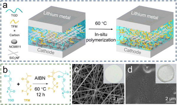 | ||
| Fig. 1 (a) Schematic illustration of the in situ preparation of GPEs. (b) Mechanism of polymerization of GPEs. SEM images with inserted digital photos of (c) SiO2NF and (d) GPE. | ||
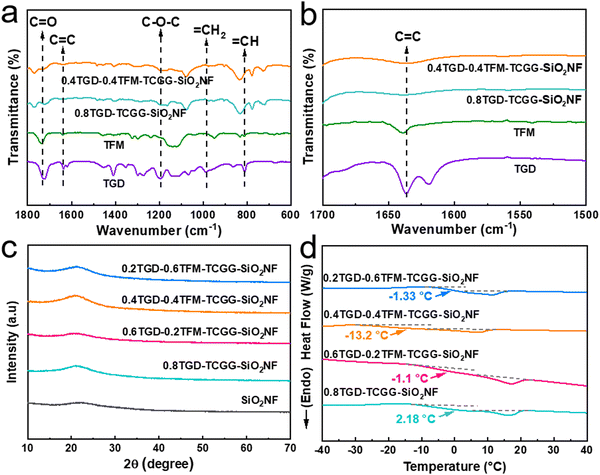
FTIR was used to characterize the functional group structure of GPEs and monomers, and the spectra are displayed in Fig. 2a. The peaks at 1745 cm−1 and 1090 cm−1 belong to the vibrations of C![[double bond, length as m-dash]](https://www.rsc.org/images/entities/char_e001.gif) O and C–O–C, respectively, which can promote the transport of Li+. The peak at 1650 cm−1, observed only in the spectra of TFM and TGD monomers, is attributed to the vibration of C
O and C–O–C, respectively, which can promote the transport of Li+. The peak at 1650 cm−1, observed only in the spectra of TFM and TGD monomers, is attributed to the vibration of C![[double bond, length as m-dash]](https://www.rsc.org/images/entities/char_e001.gif) C. After thermal treatment, these C
C. After thermal treatment, these C![[double bond, length as m-dash]](https://www.rsc.org/images/entities/char_e001.gif) C unsaturated double bonds open and polymerize, thus disappearing in the spectra of 0.8TGD-TCGG-SiO2NF and 0.4TGD-0.4TFM-TCGG-SiO2NF (Fig. 2b).29 Fig. S2 (ESI†) shows XPS spectra of the 0.4TGD-0.4TFM-TCGG-SiO2NF membrane. In the C 1s spectrum, C–C/C–H (284.78 eV), C–O (285.7 eV), C
C unsaturated double bonds open and polymerize, thus disappearing in the spectra of 0.8TGD-TCGG-SiO2NF and 0.4TGD-0.4TFM-TCGG-SiO2NF (Fig. 2b).29 Fig. S2 (ESI†) shows XPS spectra of the 0.4TGD-0.4TFM-TCGG-SiO2NF membrane. In the C 1s spectrum, C–C/C–H (284.78 eV), C–O (285.7 eV), C![[double bond, length as m-dash]](https://www.rsc.org/images/entities/char_e001.gif) O (286.7 eV), and O–C
O (286.7 eV), and O–C![[double bond, length as m-dash]](https://www.rsc.org/images/entities/char_e001.gif) O (288.9 eV) can be signed to the carbon-containing groups in the polymer chains, while C–F (290 eV) and –CF2 (290.7 eV) originate from the fluorine-containing TFM monomer. In the O 1s spectrum, C
O (288.9 eV) can be signed to the carbon-containing groups in the polymer chains, while C–F (290 eV) and –CF2 (290.7 eV) originate from the fluorine-containing TFM monomer. In the O 1s spectrum, C![[double bond, length as m-dash]](https://www.rsc.org/images/entities/char_e001.gif) O (531.3 eV) from the polymer chains and Si–O (532.5 eV) from the SiO2NF membrane are present.30 Both FTIR and XPS data demonstrate the successful polymerization of TGD and TFM monomers and the formation of the GPE membrane.
O (531.3 eV) from the polymer chains and Si–O (532.5 eV) from the SiO2NF membrane are present.30 Both FTIR and XPS data demonstrate the successful polymerization of TGD and TFM monomers and the formation of the GPE membrane.
Furthermore, all samples show a broad diffraction peak between 15° and 25° in XRD patterns (Fig. 2c), indicating the formation of amorphous phases. The amorphous phase region is the main region of Li+ transport in the polymer electrolyte, proving that the synthesized GPEs are abundant in Li+ transport channels.31 The addition of TFM can also lower the Tg of GPEs, as proved by the DSC measurements (Fig. 2d), i.e., Tg of the TFM free 0.8TGD-TCGG-SiO2NF is 2.18 °C, while the Tg values of 0.6TGD-0.2TFM-TCGG-SiO2NF, 0.4TGD-0.4TFM-TCGG-SiO2NF, and 0.2TGD-0.6TFM-TCGG-SiO2NF are −1.1 °C, −13.2 °C, and −1.33 °C, respectively. The incorporation of TFM can expand the temperature range of GPE's amorphous state by promoting polymer chain mobility, thereby enhancing Li+ migration efficiency. Moreover, the cross-linked network structure formed by TFM and TGD exhibits superior local segmental mobility, resulting in accelerated Li+ transfer rates. However, when the content of TFM is higher than 0.4, Tg decreases due to the increase of highly electronegative fluorine-containing segments that limit the movement of the polymer chains,32,33 demonstrating the importance of tailoring the TFM content.
The influence of TFM on the thermal stability of GPEs is further characterized by TG analysis. As shown in Fig. S3 (ESI†), the thermal decomposition process of GPE samples is composed of three stages. The first stage with little weight loss refers to the volatilization of water. The second stage may be caused by the loss of ester solvents in GPEs. The third stage mass loss is due to the decomposition of polymers. When the temperature increases to 110 °C, the mass loss of the 0.8TGD-TCGG-SiO2NF is 5%. By adding TFM with stable C–F bonds, the water loss from GPEs decreases obviously, indicating improved thermal stability of the electrolyte, which ensures the safe operation of the cell.
Electrochemical properties
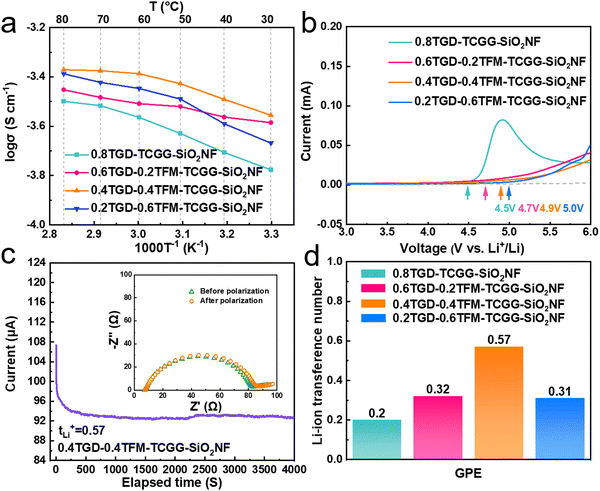
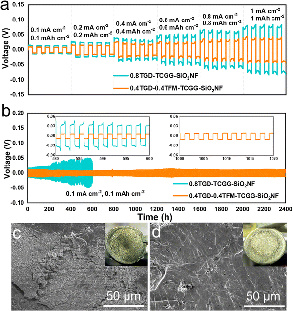
Fig. 3a shows the evolution of σ in the temperature range of 30–80 °C, and each value is listed in Table S2 (ESI†). At 30 °C, the σ values of 0.8TGD-TCGG-SiO2NF, 0.6TGD-0.2TFM-TCGG-SiO2NF, 0.4TGD-0.4TFM-TCGG-SiO2NF, and 0.2TGD-0.6TFM-TCGG-SiO2NF are determined to be 1.67 × 10⁻⁴, 2.6 × 10⁻⁴, 3.56 × 10⁻⁴, and 2.15 × 10⁻⁴ S cm−1, respectively, showing an increase in σ with the enhancement of the TFM content. However, due to the high dielectric constant of fluorine-contained TFM, overloading of it leads to a decrease in σ because the high electronegativity of fluorites in TFM prevents the transport of Li+ due to their strong internal interactions.32Fig. 3b shows the electrochemical stability windows (ESWs) of different GPEs, measured using the LSV. The oxidation potentials of the GPEs steadily increase from 4.5 V to 5 V, which may be attributed to the presence of cross-linked structures and high-voltage-tolerant fluorinated groups. tLi+ was defined via the direct current (DC) polarization method, and the currents and EIS curves before and after the polarization for different GPEs are shown individually in Fig. 3c and Fig. S4 (ESI†). Consequently, given in Fig. 3d, tLi+ of 0.8TGD-TCGG-SiO2NF, 0.6TGD-0.2TFM-TCGG-SiO2NF, 0.4TGD-0.4TFM-TCGG-SiO2NF, and 0.2TGD-0.6TFM-TCGG-SiO2NF are calculated to be 0.2, 0.32, 0.57, and 0.3 at 25 °C, respectively. With the increase of fluorine content, tLi+ increases with the highest value of 0.57 obtained from the 0.4TGD-0.4TFM-TCGG-SiO2NF. The increase in tLi+ at low TFM contents may be attributed to the Lewis acid–base interactions between functional groups (carbonyls and C–F bonds) in polymer chains and Li+ in the electrolyte.34 However, further increasing the fluorine content can hinder the transport of Li+ due to the strong internal interactions between the high electronegative fluorine chain segments and Li+, thus resulting in the decrease of tLi+.32 Nevertheless, high tLi+ generally promotes uniform Li deposition by promoting the current density limit of dendrite nucleation and delaying the nucleation process, thus effectively preventing the formation and growth of Li dendrites.35,36Li symmetric cells were assembled and measured to evaluate the electrochemical compatibility of GPEs and the Li metal. In Fig. 4a, compared to the cell with the 0.8TGD-TCGG-SiO2NF, the polarization voltage of the Li|0.4TGD-0.4TFM-TCGG-SiO2NF|Li cell decreases significantly independent of the current density applied, indicating that the introduction of TFM significantly improves the electrode/electrolyte interfacial stability and durability of the GPE. As shown in Fig. 4b, it cycles steadily at a current density of 0.1 mA cm−2 for 2400 h with a polarization voltage as low as 10 mV. In contrast, the polarization voltage of the Li|0.8TGD-TCGG-SiO2NF|Li cell increases continuously, and a short circuit occurs after 598 h, which is caused by the severe interfacial reactions.37,38
The fluorine-modified GPE exhibits higher σ and tLi+, which is beneficial in reducing polarization. Moreover, the cross-linked structure rich in electron-withdrawing groups facilitates the deposition of Li+. The abundance of C–F groups embedded in polymer segments can effectively inhibit parasitic interfacial reactions and side reactions with the Li anode. The Li|0.4TGD-0.4TFM-TCGG-SiO2NF|Li cell maintains a low planned voltage compared to the Li|0.8TGD-TCGG-SiO2NF|Li cell after 100 hours of cycling at a high current density of 0.4 mA cm−2. In Fig. S6 (ESI†), the Li|0.4TGD-0.4TFM-TCGG-SiO2NF|Li cell maintains a low polarization voltage compared to the Li|0.8TGD-TCGG-SiO2NF|Li cell after 100 hours cycling at a high current density of 0.4 mA cm−2. To explore the electrochemical evolution of the electrode surface, Li anodes disassembled from cycled Li|0.8TGD-TCGG-SiO2NF|Li and Li|0.4TGD-0.4TFM-TCGG-SiO2NF|Li cells (after 100 h at 0.4 mA cm−2) are characterized by the SEM (Fig. 4c and d). The surface of the Li anode obtained from the cell with 0.4TGD-0.4TFM-TCGG-SiO2NF is smooth and dense without obvious Li dendrites (Fig. 4d). In contrast, the Li anode cycled with 0.8TGD-TCGG-SiO2NF electrolytes exhibits a rough surface, which may be originated from uneven deposition of Li+ and lead to the formation of Li dendrites (Fig. 4c). The impedance of Li|0.8TGD-TCGG-SiO2NF|Li and Li|0.4TGD-0.4TFM-TCGG-SiO2NF|Li cells was also recorded after different aging durations, and the Nyquist plots are displayed in Fig. S5 (ESI†). After two weeks, the impedance of Li|0.8TGD-TCGG-SiO2NF|Li cells increases dramatically from 67.7 to 286.2 Ω, while that of Li|0.4TGD-0.4TFM-TCGG-SiO2NF|Li cells only increases from 95.2 to 113.5 Ω. The results above demonstrate that the fluorination-modified GPE possesses a more stable polymer network structure and exhibits less parasitic reaction with the Li metal anode, thereby demonstrating good interfacial stability.39
Furthermore, the electrochemical performance of GPEs prepared in this work is evaluated in Li metal cells with NCM811 as the cathode. The CV curves of NCM811|0.8TGD-TCGG-SiO2NF|Li and NCM811|0.4TGD-0.4TFM-TCGG-SiO2NF|Li cells are compared in Fig. S7 (ESI†). Three pairs of peaks are observed from both cells, representing the redox reaction of Co3+/Co4+ and Ni2+/Ni4+ in combination with a series of phase transitions in NCM811.40 The CV curves of NCM811|0.4TGD-0.4TFM-TCGG-SiO2NF|Li exhibit insignificant deviations and small potential differences, indicating that TFM can effectively improve the electrochemical reversibility and further enhance the cycling stability of the cell. It is noted that both curves in the first cycle are different from those of the later laps, which may be related to the formation of the solid electrolyte interphase (SEI) and the cathode electrolyte interphase (CEI) of the cell.41
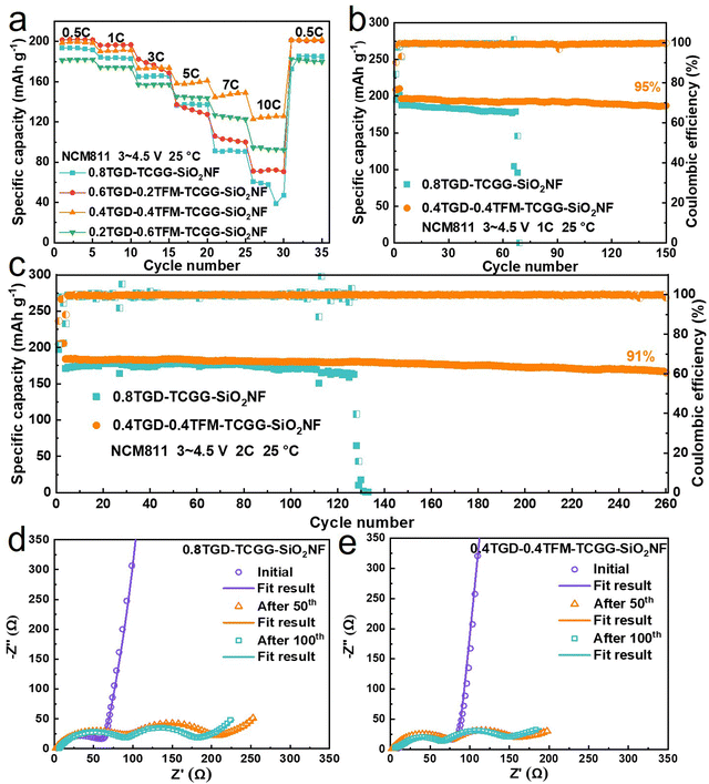
Fig. 5a compares the rate capability of NCM811‖Li cells cycled with different GPEs, the cells were cycled with the voltage range of 3.0–4.5 V at 25 °C. The charge–discharge profiles at various current rates are also shown in Fig. S8 (ESI†) (1C![[double bond, length as m-dash]](https://www.rsc.org/images/entities/char_e001.gif) 200 mA g−1). The NCM811|0.4TGD-0.4TFM-TCGG-SiO2NF|Li cell delivers discharge capacities of 199.5, 190.6, 173.7, 158.5, 147.5, and 125.0 mA h g−1 at 0.5C, 1C, 3C, 5C, 7C, and 10C, respectively, showing steadily increase difference from those values obtained from the NCM811|0.8TGD-TCGG-SiO2NF|Li cell at the same current rates (i.e., 193.4, 183.8, 165.7, 137.9, 91.8 and 57.6 mA h g−1 at 0.5C, 1C, 3C, 5C, 7C, and 10C). Regarding the long-term cycling stability, the discharge capacity of the cell with 0.4TGD-0.4TFM-TCGG-SiO2NF reaches 196.7 mA h g−1 after 150 cycles at 1C, exhibiting a high capacity retention of 95% (Fig. 5b). It also exhibits high-capacity retentions of 91% after 260 cycles at 2C (Fig. 5c) and 98% after 100 cycles at 3C (30 °C, Fig. S9, ESI†). Therefore, employing TFM can undoubtedly promote both the rate capability and the cycling performance of LMBs with high Ni NCM cathodes. In a narrow voltage range of 3.0–4.3 V, the NCM811|0.4TGD-0.4TFM-TCGG-SiO2NF|Li cell achieves 92% capacity retention even after 300 cycles at 2C (Fig. S10, ESI†). In comparison with the LMBs based on GPEs reported in the literature (Table S3, ESI†), it can be seen that the fluorine-contained group introduced in this study enables the cell to perform enhanced specific capacity and cycling stability.
200 mA g−1). The NCM811|0.4TGD-0.4TFM-TCGG-SiO2NF|Li cell delivers discharge capacities of 199.5, 190.6, 173.7, 158.5, 147.5, and 125.0 mA h g−1 at 0.5C, 1C, 3C, 5C, 7C, and 10C, respectively, showing steadily increase difference from those values obtained from the NCM811|0.8TGD-TCGG-SiO2NF|Li cell at the same current rates (i.e., 193.4, 183.8, 165.7, 137.9, 91.8 and 57.6 mA h g−1 at 0.5C, 1C, 3C, 5C, 7C, and 10C). Regarding the long-term cycling stability, the discharge capacity of the cell with 0.4TGD-0.4TFM-TCGG-SiO2NF reaches 196.7 mA h g−1 after 150 cycles at 1C, exhibiting a high capacity retention of 95% (Fig. 5b). It also exhibits high-capacity retentions of 91% after 260 cycles at 2C (Fig. 5c) and 98% after 100 cycles at 3C (30 °C, Fig. S9, ESI†). Therefore, employing TFM can undoubtedly promote both the rate capability and the cycling performance of LMBs with high Ni NCM cathodes. In a narrow voltage range of 3.0–4.3 V, the NCM811|0.4TGD-0.4TFM-TCGG-SiO2NF|Li cell achieves 92% capacity retention even after 300 cycles at 2C (Fig. S10, ESI†). In comparison with the LMBs based on GPEs reported in the literature (Table S3, ESI†), it can be seen that the fluorine-contained group introduced in this study enables the cell to perform enhanced specific capacity and cycling stability.
Fig. 5d and e show the EIS curves of NCM811|0.8TGD-TCGG-SiO2NF|Li and NCM811|0.4TGD-0.4TFM-TCGG-SiO2NF|Li cells recorded at the initial state and after 50 and 100 cycles. EIS curves consist of two semicircles and a diagonal line. The first semicircle in the high-frequency region represents the electrode interface resistance (Rsf) and its starting point represents the ohmic resistance (Rs). The second semicircle in the middle and high-frequency region is the charge transfer resistance (Rct). The EIS results fitted by the Z-view software are shown in Fig. S11 (ESI†). It is interesting to note that different from the fact that Rs of both electrolytes remains stable, Rsf and Rct decrease when prolonging the cycling number from 50 to 100 cycles, which may be due to the formation of a good Li+ transport network during long-term cycling that enables the stable transport of Li+ in the GPE. The cell containing 0.4TGD-0.4TFM-TCGG-SiO2NF exhibits lower Rsf and Rct than the one with TFM-free electrolytes during cycling, indicating that benefiting from the F-contained group, the polymer electrolytes perform enhanced stability during cycling and contribute to the formation of effective CEI and SEI layers, thus resulting in less resistance to Li+ transport.
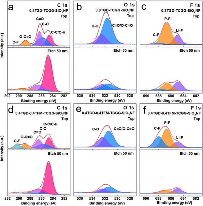
To deeply investigate the chemical composition of CEI and SEI layers, XPS depth profiling was performed on the NCM811 cathodes and Li anodes after 100 cycles. The XPS spectra of the NCM811 cathodes cycled with different GPEs are compared in Fig. 6. In C 1s spectra (Fig. 6a and d), the peak at 284.8 eV belongs to C–C/C–H. The peaks at 285.7, 286.7 and 288.9 belong to C–O, C![[double bond, length as m-dash]](https://www.rsc.org/images/entities/char_e001.gif) O and O–C
O and O–C![[double bond, length as m-dash]](https://www.rsc.org/images/entities/char_e001.gif) O, respectively. The C–F at 290 eV is derived from the organofluoride compounds.42 After Ar+ etching, all peaks of C 1s in the deep CEI layer show a decrease in intensity, and they may be formed by the oxidative decomposition of the residual polymer and carbonate electrolyte. In the O 1s spectra (Fig. 6b and e), the peaks at 531.4 and 532.5 eV are attributed to C
O, respectively. The C–F at 290 eV is derived from the organofluoride compounds.42 After Ar+ etching, all peaks of C 1s in the deep CEI layer show a decrease in intensity, and they may be formed by the oxidative decomposition of the residual polymer and carbonate electrolyte. In the O 1s spectra (Fig. 6b and e), the peaks at 531.4 and 532.5 eV are attributed to C![[double bond, length as m-dash]](https://www.rsc.org/images/entities/char_e001.gif) O/O–C
O/O–C![[double bond, length as m-dash]](https://www.rsc.org/images/entities/char_e001.gif) O and C–O, respectively. Combining the C 1s and O 1s spectra, the C
O and C–O, respectively. Combining the C 1s and O 1s spectra, the C![[double bond, length as m-dash]](https://www.rsc.org/images/entities/char_e001.gif) O/O–C
O/O–C![[double bond, length as m-dash]](https://www.rsc.org/images/entities/char_e001.gif) O, C–O, and C–C/C–H signal peaks of the 0.4TGD-0.4TFM-TCGG-SiO2NF are weaker than those of the 0.8TGD-TCGG-SiO2NF after etching, which proves that the consumption of electrolyte on the electrode surface is suppressed after the addition of TFM.43,44
O, C–O, and C–C/C–H signal peaks of the 0.4TGD-0.4TFM-TCGG-SiO2NF are weaker than those of the 0.8TGD-TCGG-SiO2NF after etching, which proves that the consumption of electrolyte on the electrode surface is suppressed after the addition of TFM.43,44
C–F (688 eV), P–F (686.78 eV) and Li–F (684.9 eV) peaks are present in the F 1s spectra (Fig. 6c and f). The C–F signal peaks on the surface of the NCM electrode cycled with 0.4TGD-0.4TFM-TCGG-SiO2NF are more intense compared to the 0.8TGD-TCGG-SiO2NF due to the participation of TFM. After etching, compared with the NCM electrode cycled with 0.4TGD-0.4TFM-TCGG-SiO2NF, 0.8TGD-TCGG-SiO2NF showed stronger P–F and Li–F signals. The P–F originates from LiPF6 and its decomposition products in the electrolyte, and the accumulation in the CEI layer also indicates that the consumption of the electrolyte is more serious. Li–F in the anode can effectively inhibit the growth of Li dendrimers, but its accumulation in the CEI may hinder the insertion–deinsertion reaction of Li+ with the cathode material.45 The above XPS results show that the fluorine-modified GPE can effectively suppress electrolyte consumption, which is beneficial for the cell to achieve a longer cycle life.
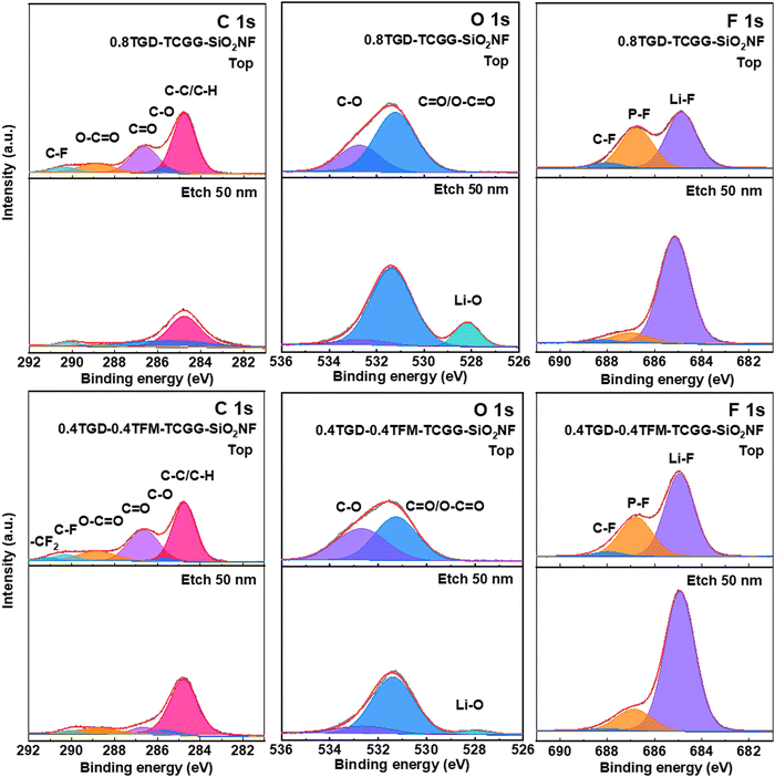
SEI composition was also characterized via XPS in combination with the Ar+ etching technique, while performing on the Li anode after 100 cycles (Fig. 7). In the spectra of C 1s, the peaks at 284.8, 285.7, 286.63, 288.8, and 290 eV belong to the C–C/C–H, C–O, C![[double bond, length as m-dash]](https://www.rsc.org/images/entities/char_e001.gif) O, O–C
O, O–C![[double bond, length as m-dash]](https://www.rsc.org/images/entities/char_e001.gif) O and C–F signals, respectively. In addition, the –CF2 (290.8 eV) peak in the 0.4TGD-0.4TFM-TCGG-SiO2NF anode belongs to TFM (Fig. 7a and d). In the O 1s spectrum, the signal peaks at 531.3 eV and 532.9 eV belong to O–C
O and C–F signals, respectively. In addition, the –CF2 (290.8 eV) peak in the 0.4TGD-0.4TFM-TCGG-SiO2NF anode belongs to TFM (Fig. 7a and d). In the O 1s spectrum, the signal peaks at 531.3 eV and 532.9 eV belong to O–C![[double bond, length as m-dash]](https://www.rsc.org/images/entities/char_e001.gif) O/C
O/C![[double bond, length as m-dash]](https://www.rsc.org/images/entities/char_e001.gif) O and C–O. The decrease in signal intensity of O 1s and C 1s after etching is due to the removal of polymer and carbonate electrolyte oxidative decomposition residues from the SEI surface by etching. Meanwhile, a signal peak belonging to Li–O (528.3 eV) appears in the inner layer of the etched SEI, and the Li–O signal may be generated by the side reaction of the Li metal with the electrolyte (Fig. 7b and e).24 After etching, the cathode cycled with 0.4TGD-0.4TFM-TCGG-SiO2NF had weaker C
O and C–O. The decrease in signal intensity of O 1s and C 1s after etching is due to the removal of polymer and carbonate electrolyte oxidative decomposition residues from the SEI surface by etching. Meanwhile, a signal peak belonging to Li–O (528.3 eV) appears in the inner layer of the etched SEI, and the Li–O signal may be generated by the side reaction of the Li metal with the electrolyte (Fig. 7b and e).24 After etching, the cathode cycled with 0.4TGD-0.4TFM-TCGG-SiO2NF had weaker C![[double bond, length as m-dash]](https://www.rsc.org/images/entities/char_e001.gif) O/O–C
O/O–C![[double bond, length as m-dash]](https://www.rsc.org/images/entities/char_e001.gif) O and C–O signals compared to the 0.8TGD-TCGG-SiO2NF and also had weaker Li–O signals, indicating that the generated SEI layer could suppress the side inversion generation between the cathode and the electrolyte. Fig. 7c and f shows the F 1s spectrum containing the signal peaks of C–F (688 eV), P–F (686.78 eV), and Li–F (684.9 eV). Compared with the cathode cycled with 0.8TGD-TCGG-SiO2NF, 0.4TGD-0.4TFM-TCGG-SiO2NF has stronger Li–F signal intensity both before and after etching, indicating that its SEI is rich in Li–F material. Li–F can inhibit the growth of Li dendrites and not only stabilize the plating behavior of Li+ but also improve interfacial compatibility.46,47 Combined with the above XPS results, the fluorine-modified GPE can reduce the electrolyte consumption during cycling, and the generated stable SEI layer rich in Li–F can effectively protect the Li metal cathode.
O and C–O signals compared to the 0.8TGD-TCGG-SiO2NF and also had weaker Li–O signals, indicating that the generated SEI layer could suppress the side inversion generation between the cathode and the electrolyte. Fig. 7c and f shows the F 1s spectrum containing the signal peaks of C–F (688 eV), P–F (686.78 eV), and Li–F (684.9 eV). Compared with the cathode cycled with 0.8TGD-TCGG-SiO2NF, 0.4TGD-0.4TFM-TCGG-SiO2NF has stronger Li–F signal intensity both before and after etching, indicating that its SEI is rich in Li–F material. Li–F can inhibit the growth of Li dendrites and not only stabilize the plating behavior of Li+ but also improve interfacial compatibility.46,47 Combined with the above XPS results, the fluorine-modified GPE can reduce the electrolyte consumption during cycling, and the generated stable SEI layer rich in Li–F can effectively protect the Li metal cathode.
Furthermore, this GPE constructed via in situ polymerization was applied to a 4 A h pouch cell assembled with the NCM811 cathode and the graphite anode. Fig. 8a shows that this pouch cell achieved 81% capacity retention after 150 cycles at 0.2C (1C = 4 A), with discharge capacities of 4.17, 3.01, and 1.61 A h at 0.2C, 0.5C, and 1C, respectively (Fig. 8b). In addition, the pouch cell can still light the LED in the case of puncture without short circuit or catching fire (Fig. S12, ESI†). The results of the pouch cell demonstrate great promise for the GPE proposed herein in commercial applications.
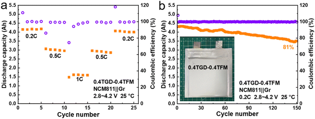 | ||
| Fig. 8 (a) Rate and (b) cycling performance of a 4 A h pouch cell with an NCM811 cathode and a graphite anode at 0.2C. | ||
4. Conclusions
In this work, a novel gel polymer electrolyte, constructed by in situ thermal polymerization of TGD and TFM on SiO2NF membranes, is designed. The polymer chain motion synergistically transfers Li+, giving the polymer electrolyte a high σ of 3.56 × 10⁻⁴ S cm−1 and a tLi+ of 0.57, illustrated by the 0.4TGD-0.4TFM-TCGG-SiO2NF sample. Meanwhile, the fluorine-containing group on the polymer chain can effectively enhance the oxidation limit of the polymer electrolyte to be as high as 4.9 V (vs. Li/Li+). In addition, the distribution of ester and fluorine groups on the polymer segments effectively regulates the Li+ deposition. The assembled Li symmetric cell with this GPE can cycle stably for 2400 h at 0.1 mA cm−2. The LMB with a configuration of NCM811|0.4TGD-0.4TFM-TCGG-SiO2NF|Li has a capacity retention of 91% after 260 cycles at 2C and a high reversible capacity of 125 mA h g−1 even at 10C (25 °C). Furthermore, when applied in pouch cells, the NCM811|0.4TGD-0.4TFM-TCGG-SiO2NF|Gr cell exhibits a capacity retention of 81% after 150 cycles at 0.2C. Therefore, the fluorinated GPE designed in this work provides a new idea to develop LMBs with high energy density; meanwhile the simple and convenient in situ polymerization process also facilitates industrial production.Conflicts of interest
There are no conflicts to declare.Acknowledgements
This work was supported by the National Key Research and Development Program of China (2022YFE0202400), the Department of Science and Technology of Zhuhai City in China (ZH22017001200059PWC), and the European Union through the Horizon 2020 framework program for research and innovation within the project “VIDCAT” (829145). We would like to thank the Analysis and Test Center of the Guangdong University of Technology for Dr Yan.References
- Z. Shen, Y. Cheng and S. Sun, et al., The critical role of inorganic nanofillers in solid polymer composite electrolyte for Li+ transportation, Carbon Energy, 2021, 3(3), 482–508 CrossRef CAS.
- H. Zhang, C. Li and G. G. Eshetu, et al., From Solid-Solution Electrodes and the Rocking-Chair Concept to Today's Batteries, Angew. Chem., Int. Ed., 2020, 59(2), 534–538 CrossRef CAS PubMed.
- S. Xin, Y. You and S. Wang, et al., Solid-State Lithium Metal Batteries Promoted by Nanotechnology: Progress and Prospects, ACS Energy Lett., 2017, 2(6), 1385–1394 CrossRef CAS.
- Y. Yang, W. Yuan and X. Zhang, et al., A review on structuralized current collectors for high-performance lithium-ion battery anodes, Appl. Energy, 2020, 276, 115464 CrossRef CAS.
- Z. Wang, Y. Wang and Z. Zhang, et al., Building Artificial Solid-Electrolyte Interphase with Uniform Intermolecular Ionic Bonds toward Dendrite-Free Lithium Metal Anodes, Adv. Funct. Mater., 2020, 30(30), 2002414 CrossRef CAS.
- Z. Hu, F. Xian and Z. Guo, et al., Nonflammable Nitrile Deep Eutectic Electrolyte Enables High-Voltage Lithium Metal Batteries, Chem. Mater., 2020, 32(8), 3405–3413 CrossRef CAS.
- L. Li, Y. Shan and X. Yang, New insights for constructing solid polymer electrolytes with ideal lithium-ion transfer channels by using inorganic filler, Mater. Today Commun., 2021, 26(5), 101910 CrossRef CAS.
- N. Zhao, W. Khokhar and Z. Bi, et al., Solid Garnet Batteries, Joule, 2019, 3(5), 1190–1199 CrossRef CAS.
- R. Rojaee, S. Cavallo and S. Mogurampelly, et al., Highly-Cyclable Room-Temperature Phosphorene Polymer Electrolyte Composites for Li Metal Batteries, Adv. Funct. Mater., 2020, 30(32), 1910749 CrossRef CAS.
- J. Lopez, D. G. Mackanic and Y. Cui, et al., Designing polymers for advanced battery chemistries, Nat. Rev. Mater., 2019, 4(5), 312–330 CrossRef CAS.
- W.-P. Wang, J. Zhang and Y.-X. Yin, et al., A Rational Reconfiguration of Electrolyte for High-Energy and Long-Life Lithium-Chalcogen Batteries, Adv. Mater., 2020, 32(23), 2000302 CrossRef CAS PubMed.
- Z. Lin, X. Guo and Z. Wang, et al., A wide-temperature superior ionic conductive polymer electrolyte for lithium metal battery, Nano Energy, 2020, 73, 104786 CrossRef CAS.
- L. Bai, S. Ghiassinejad and J. Brassinne, et al., High Salt-Content Plasticized Flame-Retardant Polymer Electrolytes, ACS Appl. Mater. Interfaces, 2021, 13(37), 44844–44859 CrossRef CAS PubMed.
- Z. Chen, Y. Yang and Q. Su, et al., A Flexible Semi-Interpenetrating Network-Enhanced Ionogel Polymer Electrolyte for Highly Stable and Safe Lithium Metal Batteries, ACS Appl. Mater. Interfaces, 2021, 13(35), 41946–41955 CrossRef CAS PubMed.
- J. Hu, K. Chen and Z. Yao, et al., Unlocking solid-state conversion batteries reinforced by hierarchical microsphere stacked polymer electrolyte, Sci. Bull., 2021, 66(7), 694–707 CrossRef CAS PubMed.
- W. Ren, C. Ding and X. Fu, et al., Advanced gel polymer electrolytes for safe and durable lithium metal batteries: Challenges, strategies, and perspectives, Energy Storage Mater., 2021, 34, 515–535 CrossRef.
- S. Z. Zhang, X. L. Wang and X. H. Xia, et al., Smart construction of intimate interface between solid polymer electrolyte and 3D-array electrode for quasi-solid-state lithium ion batteries, J. Power Sources, 2019, 434, 226726.1–226726.6 Search PubMed.
- W. Liang, Y. Shao and Y.-M. Chen, et al., A 4 V Cathode Compatible, Superionic Conductive Solid Polymer Electrolyte for Solid Lithium Metal Batteries with Long Cycle Life. Acs Applied Energy, Materials, 2018, 1(11), 6064–6071 CAS.
- H. Wang, Q. Wang and X. Cao, et al., Thiol-Branched Solid Polymer Electrolyte Featuring High Strength, Toughness, and Lithium Ionic Conductivity for Lithium-Metal Batteries, Adv. Mater., 2020, 32(37), 2001259 CrossRef CAS PubMed.
- X. Liu, C. Xu and M. Wang, et al., Trifluoromethyltrimethylsilane: Nucleophilic Trifluoromethylation and Beyond, Chem. Rev., 2015, 115(2), 683–730 CrossRef CAS PubMed.
- H. Zhang, X. Ma and C. Lin, et al., Gel polymer electrolyte-based on PVDF/fluorinated amphiphilic copolymer blends for high performance lithium-ion batteries, RSC Adv., 2014, 4(64), 33713 RSC.
- P.-Y. Ji, J. Fang and Y.-Y. Zhang, et al., Novel Single Lithium-Ion Conducting Polymer Electrolyte Based on Poly(hexafluorobutyl methacrylate-co-lithium allyl sulfonate) for Lithium-Ion Batteries, ChemElectroChem, 2017, 4(9), 2352–2358 CrossRef CAS.
- A. Ccs, A. Mh and B. Ra, et al., Cyclic carbonate for highly stable cycling of high voltage lithium metal batteries, Energy Storage Mater., 2019, 17, 284–292 CrossRef.
- Q. Yang, J. Hu and J. Meng, et al., C-F-rich oil drop as a non-expendable fluid interface modifier with low surface energy to stabilize a Li metal anode, Energy Environ. Sci., 2021, 14(6), 3621–3631 RSC.
- B. Liu, Y. Huang and H. Cao, et al., A novel porous gel polymer electrolyte based on poly(acrylonitrile-polyhedral oligomeric silsesquioxane) with high performances for lithium-ion batteries, J. Membr. Sci., 2018, 545, 140–149 CrossRef CAS.
- A. Song, Y. Huang and X. Zhong, et al., Novel lignocellulose based gel polymer electrolyte with higher comprehensive performances for rechargeable lithium-sulfur battery, J. Membr. Sci., 2018, 556, 203–213 CrossRef CAS.
- Z. Shen, J. Zhong and J. Chen, et al., SiO2 nanofiber composite gel polymer electrolyte by in-situ polymerization for stable Li metal batteries, Chin. Chem. Lett., 2023, 34, 3 Search PubMed.
- V. Vijayakumar, B. Anothumakkool and S. Kurungot, et al., In situ polymerization process: an essential design tool for lithium polymer batteries, Energy Environ. Sci., 2021, 14(5), 2708–2788 RSC.
- H. Duan, Y.-X. Yin and X.-X. Zeng, et al., In-situ plasticized polymer electrolyte with double-network for flexible solid-state lithium-metal batteries, Energy Storage Mater., 2018, 10, 85–91 CrossRef.
- Z. Geng, Y. L. Huang and G. C. Sun, et al., In-situ polymerized solid-state electrolytes with stable cycling for Li/LiCoO2 batteries, Nano Energy, 2022, 91, 106679 CrossRef CAS.
- Y. Zhang, W. Lu and L. Cong, et al., Cross-linking network based on Poly(ethylene oxide): Solid polymer electrolyte for room temperature lithium battery, J. Power Sources, 2019, 420, 63–72 CrossRef CAS.
- Y. Wang, S. S. Chen and Z. Y. Li, et al., In-situ generation of fluorinated polycarbonate copolymer solid electrolytes for high-voltage Li-metal batteries, Energy Storage Mater., 2022, 45, 474–483 CrossRef.
- B. Sun, J. Mindemark and E. V. Morozov, et al., Ion transport in polycarbonate based solid polymer electrolytes: experimental and computational investigations, Phys. Chem. Chem. Phys., 2016, 18(14), 9504–9513 RSC.
- Y. Ma, Q. Sun and Z. Wang, et al., Improved interfacial chemistry and enhanced high voltage-resistance capability of an in situ polymerized electrolyte for LiNi0.8Co0.15Al0.05O2-Li batteries, J. Mater. Chem. A, 2021, 9(6), 3597–3604 RSC.
- L. Li, H. Duan and J. Li, et al., Toward High Performance All-Solid-State Lithium Batteries with High-Voltage Cathode Materials: Design Strategies for Solid Electrolytes, Cathode Interfaces, and Composite Electrodes, Adv. Energy Mater., 2021, 11(28), 2003154 CrossRef CAS.
- M. D. Tikekar, L. A. Archer and D. L. Koch, Stabilizing electrodeposition in elastic solid electrolytes containing immobilized anions, Sci. Adv., 2016, 2(7), 1600320 CrossRef PubMed.
- T. Wang, Y. Li and J. Zhang, et al., Immunizing lithium metal anodes against dendrite growth using protein molecules to achieve high energy batteries, Nat. Commun., 2020, 11(1), 5429 CrossRef CAS PubMed.
- Z. Ju, J. Nai and Y. Wang, et al., Biomacromolecules enabled dendrite-free lithium metal battery and its origin revealed by cryo-electron microscopy, Nat. Commun., 2020, 11(1), 488 CrossRef CAS PubMed.
- Q. Sun, S. Wang and Y. Ma, et al., Fumaronitrile-fixed in-situ gel polymer electrolyte balancing high safety and superior electrochemical performance for Li metal batteries, Energy Storage Mater., 2022, 44, 537–546 CrossRef.
- K. Lin, S. Yang and Z. Shi, et al., Knitting a sweater with UV-induced in situ polymerization of poly (pyrrole-co-citral nitrile) on Ni-rich layer oxide cathode materials for lithium ion batteries, J. Power Sources, 2022, 520, 230768 CrossRef CAS.
- Z. Shen, J. Zhong and W. Xie, et al., Effect of LiTFSI and LiFSI on Cycling Performance of Lithium Metal Batteries Using Thermoplastic Polyurethane/Halloysite Nanotubes Solid Electrolyte, Acta Metall. Sin., 2021, 34(3), 359–372 CrossRef CAS.
- J. G. Han, J. Bin Lee and A. Cha, et al., Unsymmetrical fluorinated malonatoborate as an amphoteric additive for high-energy-density lithium-ion batteries, Energy Environ. Sci., 2018, 11(6), 1552–1562 RSC.
- L. Qiao, U. Oteo and Y. Zhang, et al., Trifluoromethyl-free anion for highly stable lithium metal polymer batteries, Energy Storage Mater., 2020, 32, 225–233 CrossRef.
- Y. Ma, K. Chen and J. Ma, et al., A biomass based free radical scavenger binder endowing a compatible cathode interface for 5 V lithium-ion batteries, Energy Environ. Sci., 2019, 12(1), 273–280 RSC.
- S. Liu, J. Su and J. Zhao, et al., Unraveling the capacity fading mechanisms of LiNi0.6Co0.2Mn0.2O2 at elevated temperatures, J. Power Sources, 2018, 393, 92–98 CrossRef CAS.
- Y. Lu, Z. Tu and L. A. Archer, Stable lithium electrodeposition in liquid and nanoporous solid electrolytes, Nat. Mater., 2014, 13(10), 961–969 CrossRef CAS PubMed.
- S. J. Tan, J. Yue and X. C. Hu, et al., Nitriding Interface Regulated Lithium Plating Enables Flame-Retardant Electrolytes for High-Voltage Lithium Metal Batteries, Angew. Chem., Int. Ed., 2019, 58(23), 7802–7807 CrossRef CAS PubMed.
Footnote |
| † Electronic supplementary information (ESI) available. See DOI: https://doi.org/10.1039/d3qm00362k |
| This journal is © the Partner Organisations 2023 |

