
 Open Access Article
 This Open Access Article is licensed under a
 Creative Commons Attribution 3.0 Unported Licence
Mechanistic insights into the electrochemical reduction of CO2 to CO on Ni(salphen) complexes†
Sara
Realista
 a,
Paulo J.
Costa
b,
Luisa B.
Maia
c,
Maria José
Calhorda
*b and
Paulo N.
Martinho
*a
a,
Paulo J.
Costa
b,
Luisa B.
Maia
c,
Maria José
Calhorda
*b and
Paulo N.
Martinho
*a
aCentro de Química Estrutural, Institute of Molecular Sciences, Departamento de Química e Bioquímica, Faculdade de Ciências, Universidade de Lisboa, Campo Grande, 1749-016 Lisboa, Portugal. E-mail: pnmartinho@ciencias.ulisboa.pt
bBioISI - Instituto de Biosistemas e Ciências Integrativas, Faculdade de Ciências, Universidade de Lisboa, 1749-016, Lisboa, Portugal. E-mail: mjc@ciencias.ulisboa.pt
cLAQV, REQUIMTE, Department of Chemistry, NOVA School of Science and Technology|FCT NOVA, Campus de Caparica, 2829-516 Caparica, Portugal
First published on 23rd May 2023
Abstract
Cyclic voltammetry and bulk electrolysis showed that [Ni(II)(salphen)] [1], [Ni(II)(tBu-salphen)] [2], and a binuclear Ni(II) compound combining salphen and tBu-salphen [3] react with CO2 to yield a metal–carbonyl species that is stable under an oxygen free atmosphere. Upon exposure to air, a stoichiometric amount of CO is released (detected by gas chromatography) and protonation regenerates the initial complex. To shed light on the mechanism of CO2 reduction and O2-dependent CO release by [1], UV-vis, EPR and SEC-IR spectroscopy studies complemented with DFT calculations were performed. It is proposed that the mono reduced [Ni(I)(salphen)]−, 2[1]−, formed a CO2 complex, 2[1(CO2)]−, which was then further reduced to 3[1(CO2)]2−. After addition of two protons, the coordinated CO2 was reduced to CO and released, regenerating 1[1]. Alternatively, 2[1(CO2)]− is protonated and then reduced to the same intermediate as before, continuing the same way. In the second cycle, the CO released competed with CO2 and coordinated to 2[1]− much more strongly, thereby deactivating the system. The new 2[1(CO)]− was reduced to 3[1(CO)]2− which was identified by comparison of experimental spectroscopic (UV-vis, EPR, SEC-IR) data with DFT calculated parameters.
Introduction
Despite the effort of moving toward non-fossil alternative energy sources, the increasing concentration of CO2 in the atmosphere has contributed to challenging chemists into developing ways to capture this gas or to convert it into added-value chemicals.1,2 One of them is carbon monoxide (CO), considered a silent killer gas, but still employed in several important applications from therapeutics to industry. Indeed, in small amounts, CO has cell protective, anti-inflammatory and vasodilatory properties,3 and CO-releasing compounds have been developed for this purpose.4,5 This gas also plays a key role in many relevant chemical reactions such as Fischer–Tropsch6 or as a C1 source for several carbonylation reactions (e.g. hydroformylation or acetic acid production).7 Reduction of CO2 is a viable process to afford CO8–10 and, if available on a large scale, this might decrease its excessive amount in the atmosphere, which has compromised the delicate energy balance of the Earth.11–13 However, the efficient storage and purification of large amounts of CO create a problem. Several solutions for CO elimination/purification range from diffusion through membranes,14 methanation15,16 and/or oxidation,17 to capture and separation with high surface area materials, namely metal–organic frameworks,18,19 zeolites,20 or activated carbon.21,22 Nonetheless, most of these materials do not bind CO strongly enough for storage, selective removal, and further utilisation. On the other hand, in other cases, CO binds so strongly that the adsorption is irreversible.23 This happens when a strong M–CO back donation component in electron-rich transition metal complexes contributes to strengthening the M–CO bond.24 The strategy to form a weak M–C includes the decrease of this component, so that the σ ligand to metal component becomes dominant, as found in uncommon cationic carbonyl complexes.23 This feature has been searched in carbon monoxide-releasing molecules (CO-RMs).25The capability of reducing CO2 to CO has been found in a variety of transition metal complexes, ranging from 3d metals to heavier ones.9,10,26–30 Nickel, the metal that interests us in this work, has been widely applied to this problem. [Ni(II)cyclam]Cl2 (cyclam = 1,4,8,11-tetra-azacyclotetradecane) was reported to electrochemically reduce CO2 in an efficient way in 1984, the process being still favourable in water, since water reduction was much slower.31 Further studies were pursued by the same group to understand the mechanism and the factors controlling the outcome of the process.32 They were later taken into account to explore the reaction mechanisms and the factors controlling them using experimental methods,33,34 spectrochemical investigations,35 and computational approaches.36 During this time, other nickel systems were developed and their capability in CO2 reduction was tested. Substitution of one N donor atom by chalcogens led to Ni[iso-cyclam]2+ species, which did not improve the performance of the original complex.37 Nickel(bis-dithiolene) complexes, inspired by formate- and CO-dehydrogenases, converted CO2 to CO, which was further reduced to formate during the course of the electroreduction.38 Several pincer ligand complexes contributed to understanding the chemistry of CO2 reduction associated with the coordination geometry and the presence of other ligands.39,40
In this work, we address the electroreduction of CO2 with Schiff base Ni(II) complexes, by means of electrochemical techniques and spectroelectrochemistry, complemented by a DFT41 computational study.
Results and discussion
Electrochemical studies – cyclic voltammetry
Two mononuclear [1] and [2], and one binuclear [3], Ni(II)(R-salphen) complexes were selected to study the electrochemical reduction of CO2 (R-salphen = N,N′-bis(3,5-R-salicylidene)-1,2-phenylenediamine, with R = H or tBu; see Fig. 1). Their synthesis and characterisation have been previously reported, as well as their performance in the O2 reduction reaction.42,43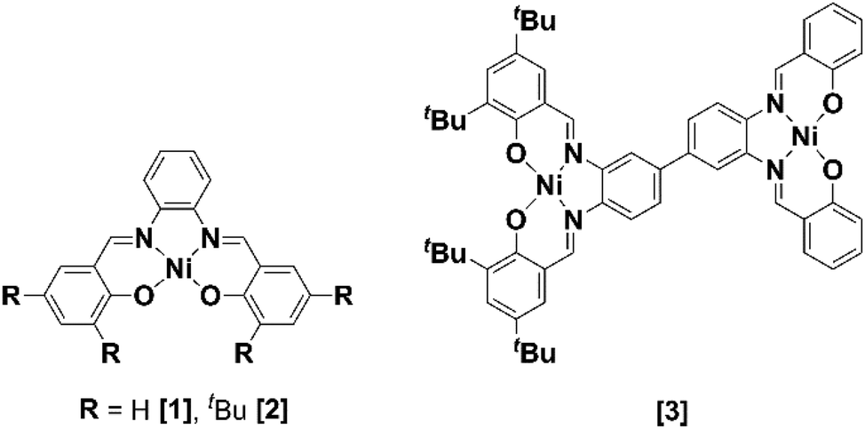 | ||
| Fig. 1 Ni(II) Schiff base complexes [1]–[3]. | ||
The cyclic voltammograms of Ni(II) complexes [1]–[3] in dimethylformamide (DMF) solution using glassy carbon as a working electrode are shown in Fig. 2. Under argon, [1] shows an irreversible ligand-based reduction at −1.38 V vs. SCE (confirmed by experiments at different scan rates – Fig. S1†), while the tBu derivative [2] is more difficult to reduce (−1.57 V vs. SCE) and the process shows a quasi-reversible behaviour.44 Complex [3] contains two Ni(II) centres with different ligand environments corresponding to the two subunits based on [1] and [2], and resulting in an asymmetric electron density distribution in the molecule. A distinct electrochemical behaviour is foreseen for each subunit. The two ligand-based reductions at −1.32 and −1.64 V vs. SCE (Fig. 2) occur at potential values different from those obtained for the mononuclear complexes [1] and [2]. They are easier for the former and more difficult than for the latter, reflecting the electronic delocalisation of the π system. The frontier orbitals of [1], [2] and [3], obtained from a full geometry optimisation, are in agreement with the proposed ligand-based reduction process (Fig. S2–S4†).
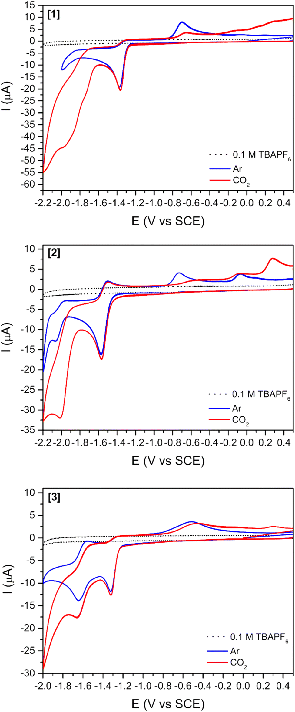 | ||
| Fig. 2 Cyclic voltammograms of complexes [1], [2], and [3] (1 mM) in DMF, argon, or carbon dioxide saturated solutions using TBAPF6 as supporting electrolyte (0.1 M) at 100 mV s−1. Glassy carbon (3 mm diameter) was used as working, platinum wire as counter and SCE as reference electrodes. | ||
The reduction of complexes Ni(salphen) and Ni(salen) (salen = N,N′-bis(salicylidene)ethylenediamine) has been well studied and their behaviour is distinct. The reduction of salen complexes takes place at the metal, and the Ni(I) species formed have been identified, among others, by EPR and electronic absorption.44,45 The reduction potential for the Ni(salphen) complexes was observed at −1.30 V in DMF, very close to the value found in this work. The chemical reduction of the Ni(salphen) complex in the presence of alkali metals, associated with a colour change from red to green, led to the structural characterisation of a Ni(II) dimer, [Ni(salphen)Na(THF)3]2, in which the two units bind through one imine carbon of each unit (see [Ni2(salphen)2]2− in Fig. S5†).46 A more detailed electrochemical study of the reduction revealed that the one electron reduction of Ni(salphen) is followed by a chemical reaction to form the same dimer as in the reaction with Na, suggesting that the ligand is involved in the reaction. This species may oxidise back to the initial Ni(II) complex, but it can also continue to be reduced. The authors propose that Ni(II) is reduced to Ni(I) after receiving the second electron and cleaving the C–C bond of the dimer.45 A simple look at the frontier orbitals (Fig. S2–S4†) shows for the three complexes a LUMO localised in the salphen ligand, apparently supporting the assignment of the first reduction occurring in the ligand. The LUMOs have a large electron density in the imine carbon, explaining the occurrence of the new C–C bond formation there. However, this matter will be discussed more deeply later (see DFT calculations section).
After saturation with CO2, an increase in the cathodic current is observed for all complexes (Fig. 2) indicating the reactivity of all three compounds towards this gas. This current increase is observed at more negative potentials than the reduction observed under an argon atmosphere, suggesting that reduction processes occur in a different species. The increase in current starts earlier for [3] (−1.43 V vs. SCE right after the ligand-based reduction) than for [1] (−1.60 V vs. SCE) and [2] (−1.80 V vs. SCE), thus showing again that the two subunits do not act independently.
The addition of a weak Brønsted acid (water) at several concentrations was studied (Fig. 3 and S5†) for compounds [1]–[3]. The effect of water as a proton source for the reduction peak at −1.6 V vs. SCE is two-fold: (1) the peak slightly shifts towards more positive potentials with increasing concentrations of water. This shift might be simply related to processes involving protons, which drive the reduction peak towards more positive values. (2) The increases in cathodic current with increasing concentrations of water agree with previous reports stating that the addition of a proton source would enhance the catalytic reduction of CO2.26,47 This increase in the cathodic current is more relevant for [3] (Fig. 3) as it is observed with as little concentration as 100 mM H2O. For [1] and [2] (Fig. S6†), a considerable increase in the cathodic current is only observable for the highest amount of water added (3000 mM).
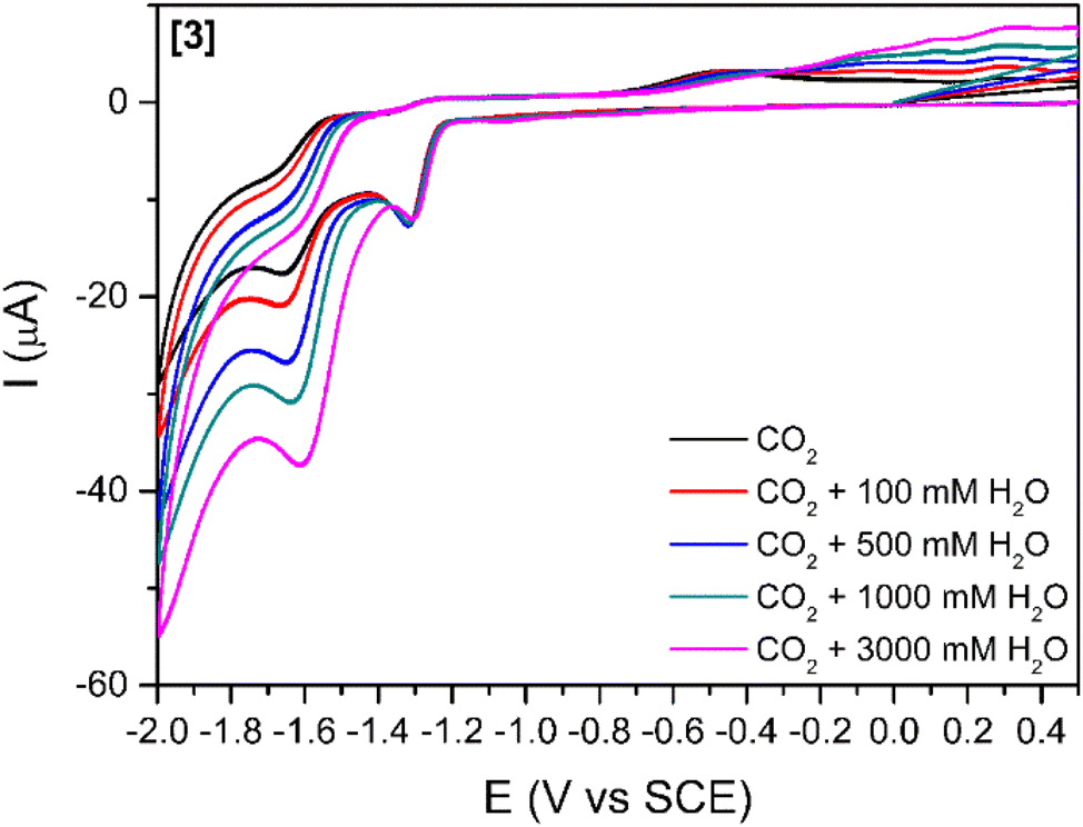 | ||
| Fig. 3 Cyclic voltammograms of complex [3] (1 mM) in DMF, carbon dioxide saturated solutions using TBAPF6 as supporting electrolyte (0.1 M) at 100 mV s−1. Effect of different concentrations of added water. | ||
Electrochemical studies – controlled-potential electrolysis
Controlled potential electrolysis (CPE) of complexes [1]–[3] (Fig. S7 and S8†) was performed at different potentials for 3 hours, using 1 M water as a proton source (Table 1), to gather more information about the interaction between CO2 and all the complexes. The CPE experiments were performed at −1.7 V for [1], −1.9 V and −2.1 V for [2] and −1.6 V for [3]vs. SCE.| Complex | Potential | n(CO) | n(H2) | n(CO)a |
|---|---|---|---|---|
| a After adding 1 mL of air. b The observation of CO at this working potential might be related to the degradation of the initial complex and is corroborated by the current behaviour during electrolysis (Fig. S8†). c Obtained for the CPE at −2.1 V. | ||||
| [1] | −1.7 | 0 | 1.1 | 0.41 |
| [2] | −1.9/−2.1 | 0/0.21b | 0.23/1.9 | 0.63c |
| [3] | −1.6 | 0 | 0.40 | 0.60 |
Surprisingly, the analysis of the head space gases only showed the presence of H2 in a low quantity and no traces of CO, except for the CPE for [2] at −2.1 V vs. SCE. The decrease in the cathodic current during CPE (Fig. S7 and S8†) indicates conversion of the initial compound into other species. Additionally, CPE was accompanied by a dramatic electrolyte colour change from red to deep brown (Fig. S9†), which reverted to the initial red coloured solution after the CPE solution was exposed to air for several hours. This suggested that atmospheric oxygen could participate in a reaction with the product formed after CPE. Further CPE experiments were performed under the same conditions as previously, with 1 mL amounts of air injected into the electrolyte after the CPE. The headspace was then analysed and the volume of CO, detected as the main gas, increased with the amount of air injected (see the values for the addition of 1 mL in Table 1). The presence of H2O2 was detected in the bulk electrolysis solution by UV-vis spectroscopy (Fig. S10†). A new absorption band is observable at 468 nm after the addition of an Fe(II) aqueous solution. This band is related to the oxidation of Fe(II) to Fe(III) and confirms the formation of hydrogen peroxide.
As previously stated, the reduction of CO2 occurs at a more positive potential for [3], followed by [1], and the most negative potential was observed for [2]. For [2], two different CPEs were performed, since CO was never observed in the first CPE, performed at −1.9 V vs. SCE, even after air injection. In the second electrolysis (−2.1 V vs. SCE), CO and a high amount of H2 were detected, but the evolution of the current with time was very different from what was observed for [1] and [3], which might indicate complete degradation of the complex (Fig. S8 and S7†).
The results summarised in Table 1 show that CO2 was reduced to CO though this gas was not detected in the headspace immediately after the electrolysis, being only released after the addition of air or O2. This also suggests that oxygen may trigger the release of CO from the Ni–CO species. The TONCO evolves towards 1 with the amount of air added, which agrees with a single-turnover mechanism, resulting in a quantitative CO production. These aspects will be discussed later. The binuclear Ni(II) complex [3] is more efficient than [1] for CO2 reduction, and releases a larger amount of CO after adding 1 mL of air, without suffering the limitations of complex [2]. Thus, complex [3] was studied under a CO atmosphere and cyclic voltammograms are available in the ESI (Fig. S11†). No significant differences were observed after saturation of the solution with carbon monoxide which may mean that the reaction is not within the time scale of the cyclic voltammetry experiments.
Two consecutive CPE were carried out for [3] to understand both the nature and extension of the reversibility of this Ni(II) system (Fig. 4a). The procedure started with a CPE, followed by bubbling air in the solution, saturating the solution with CO2 and performing a second CPE applying the same initial conditions. The current and charge evolution with time (Fig. 4a) are similar for both electrolysis. Additionally, linear voltammetry was performed in all four steps for further comparison (Fig. 4b).
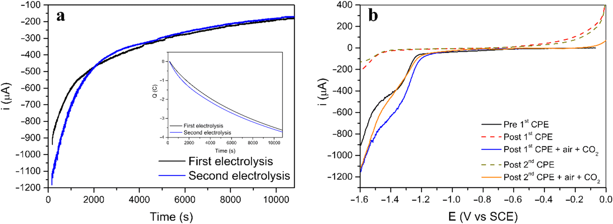 | ||
| Fig. 4 (a) Current and charge (inset) behavior during both CPE of complex [3]. (b) Linear voltammograms of [3] in DMF using TBAPF6 as supporting electrolyte (0.1 M) at 10 mV s−1. Glassy carbon was used as working electrode, platinum wire as counter and SCE as reference electrode. | ||
Before the first electrolysis, the linear voltammogram (black line) shows the reduction process at −1.3 V vs. SCE (before first CPE) which disappears after the CPE (red dashed line, post first CPE). However, when the solution is saturated with air, followed by saturation with CO2, the same process reappears, suggesting that the initial complex was regenerated (blue line, post first CPE + air + CO2). A second CPE resulted in a linear voltammogram similar to the first electrolysis, and the new green dashed line (post second CPE) line almost superimposes completely on the red dashed line (post 1st CPE). After the second regeneration step (saturation with air and CO2) the voltammogram (red line) shows again the reduction feature (post second CPE + air + CO2, comparable to post first CPE + air + CO2 and to the initial before first CPE).
Computational studies: Ni(II)(R-salphen) complexes, [1], [2], and [3]
DFT and TDDFT calculations41 were performed using the PBE1PBE functional48 (Gaussian0949) in order to identify the species detected by IR, UV-vis absorption spectroscopy and EPR (see below), and to understand the mechanism of CO2 binding, reduction, and release. Complex [1] was used as the model for the reaction with CO2 (see Computational details section) whereas to study the electronic structure of these complexes, the geometries of the parent complexes [1], [2] and [3] were fully optimised, as well as their first and second reduction products. The first electron will occupy the LUMO, but the second electron may also occupy the LUMO (singlet state) or the next unoccupied orbital, the LUMO+1 (triplet state). A similar study has previously reported the reactivity of the Ni(II)(salphen) complexes during oxidation.42,43In complex [1], d8 Ni(II) has a square planar environment (Fig. 5, left), as expected. The HOMO is mainly located on the metal, being π-antibonding between the metal and the salphen ligand, while the LUMO is a ligand π orbital. Upon reduction, the metal coordination environment becomes puckered (N–Ni–O angles of 175.2°), the singly occupied molecular orbital (SOMO) is σ-antibonding (dx2−y2) and the LUMO remains a ligand π orbital (Fig. 5, centre). It is noticed that due to changes in electron repulsion, the extra electron in 2[1]− occupies an orbital delocalised over the metal and the ligand. This nature agrees with the proposals of earlier works on the electrochemical reduction of Ni(II)salphen complexes, as discussed above.44,45 The Ni atom contributes 47% to the SOMO and the ligand 53%, which allows us to classify the new species as a Ni(I) complex.
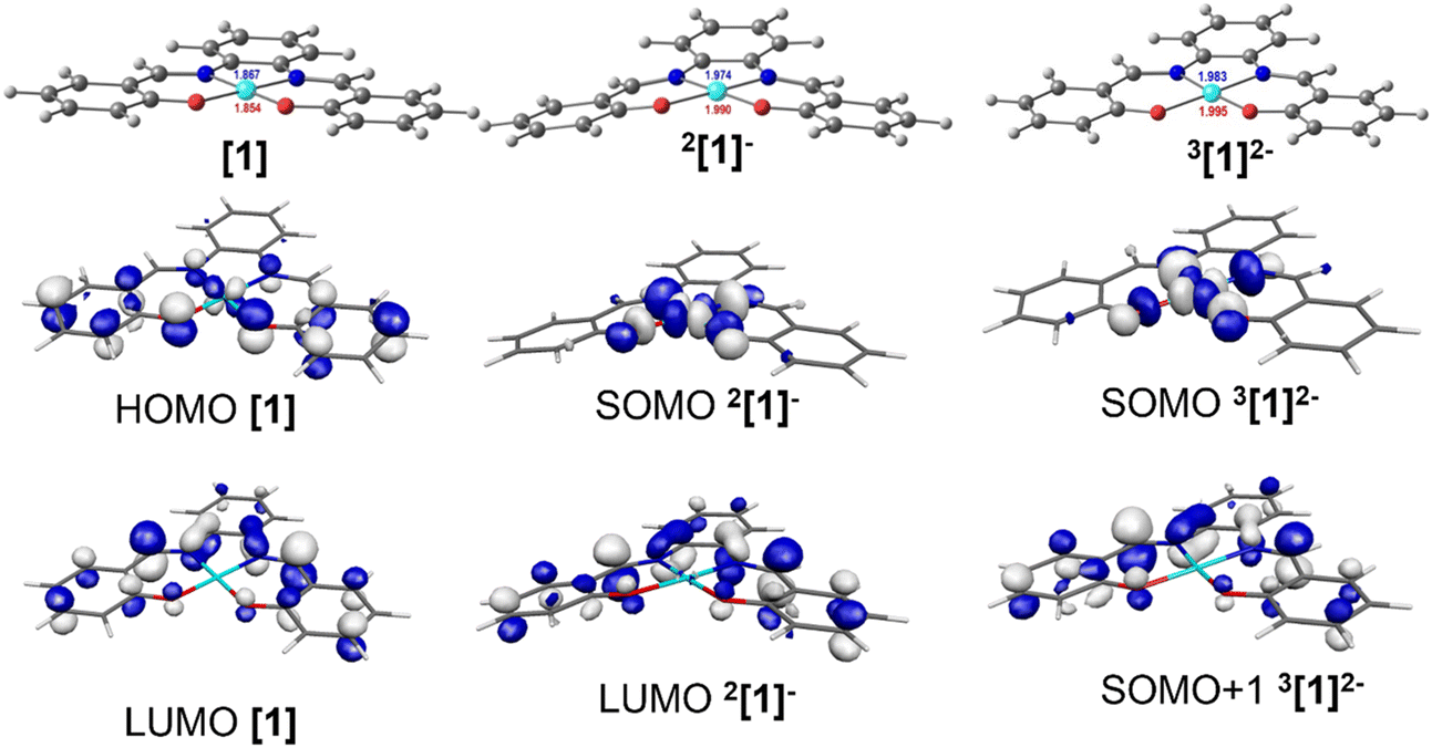 | ||
| Fig. 5 DFT optimised geometries of complex [1] (left), its one-electron 2[1]− (centre) and two-electron 3[1]2− (right) reduction products, with the HOMO and LUMO of [1], the SOMO and LUMO of 2[1]−, and the SOMO (dx2−y2 nickel orbital) and SOMO+1 (ligand based orbital) of 3[1]2−. The SOMO and SOMO+1 of 3[1]2− will be occupied by the first and the second electrons. | ||
The second reduction may lead to the occupation of the SOMO of [1]−, giving rise to a singlet state species 1[1]2−, or to the occupation of the LUMO of [1]−, creating a triplet state species 3[1]2−. The energy of the triplet state structure is 15.5 kcal mol−1 lower than that of the 1[1]2− singlet. Since the LUMO that accepted the second electron is localised in the salphen ligand (the contribution of Ni to this orbital is ∼0.2%), this second reduction takes place in the ligand (Fig. 5, right). The second electron reduction of Ni(II)salphen has been less studied experimentally than the first. However, the proposal of Vianello and coworkers45 was that, after receiving two electrons, the initial Ni(II) complex contained Ni(I). Pure metal orbitals are rare, and the second reduction seems to take place in a pure ligand orbital (Fig. 5, right). Therefore, it seems appropriate to accept that both [1]− and 3[1]2− are Ni(I) complexes. 3[1]2− may be represented as 3[Ni(I)(salphen˙)]2−.
The frontier orbitals (SOMO and SOMO+1) of the lower energy 2-electron reduced species 3[1]2− (Fig. 5) reflect the nature of the orbitals discussed. The geometry of this dianion is again practically planar, like complex [1], while the 2[1]− singlet species is puckered (Fig. 5). The frontier orbitals of [1], [2], [3], 2[1]−, 1[1]2−, and 3[1]2− are shown in Fig. S2–S4 and S12–S14.†
Mechanistic investigations
Infrared spectroelectrochemical (SEC-IR) experiments (see more details in the legend of Fig. 6 and the Experimental section) were performed on 5 mM CO2 saturated DMF solution of [1] to identify the Ni–CO species present at the end of the reaction. A new peak appears around 1935 cm−1 when potential is applied (−1.45 V vs. Ag pseudo-reference) and grows with time as clearly seen in Fig. 6 (left). This peak, in the energy window characteristic of terminal carbonyls, is attributed to the Ni–CO species and the frequency is comparable to that found for the Ni–CO stretching mode in the corresponding species of the Ni(cyclam) system (1955 cm−1).34 No significant peak can be assigned to [Ni(CO)4] (2042 cm−1),34 but a signal at around 2142 cm−1, characteristic of free CO, is observed. Since the SEC-IR experiments were not performed in a glove box, some O2 might be present triggering CO release.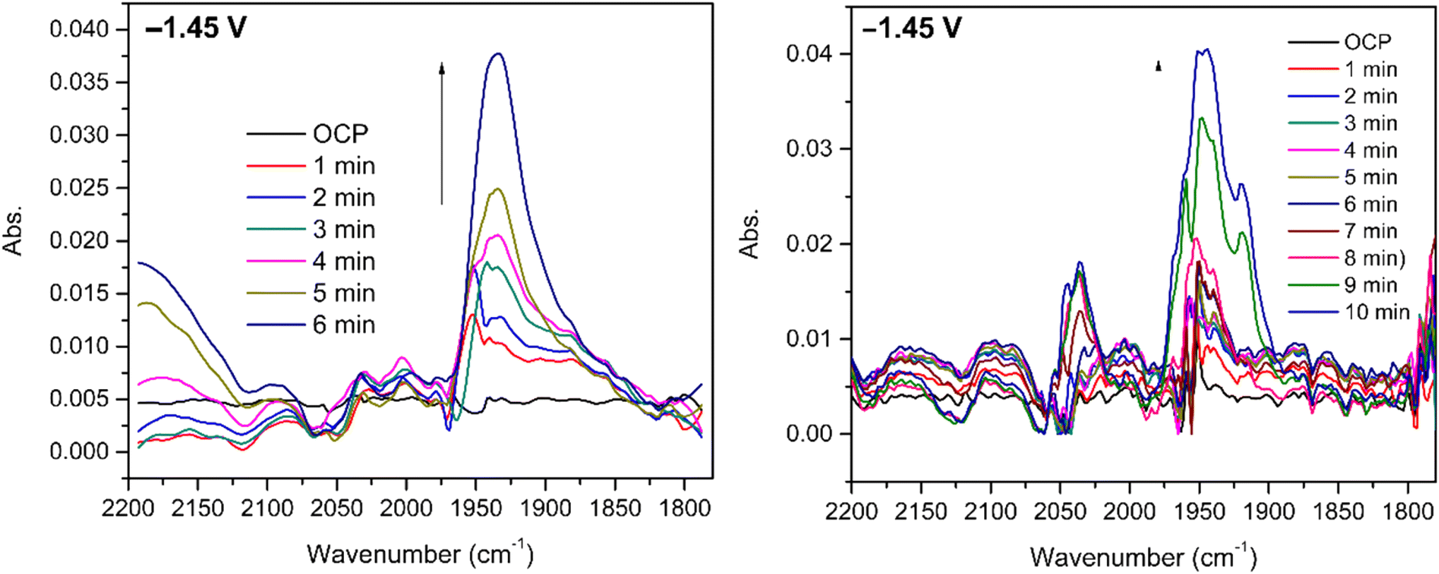 | ||
| Fig. 6 SEC-IR experiments at −1.45 V vs. Ag pseudo-reference using 5 mM of [1] and 0.1 M TBAPF6 in a CO2 saturated DMF solution, Pt grids as working and counter electrodes and Ag wire as a pseudo-reference electrode: under a CO2 atmosphere (left); under a CO atmosphere (right). | ||
The experiment was repeated using the same conditions under a CO atmosphere and a signal, observed at the same frequency in Fig. 6 (right), although with a slightly different shape, suggesting that the same intermediate is formed.
UV-vis spectroscopy was performed to assist the identification of the species formed after CPE of complex [1] both under CO2 (Fig. S7†) and CO (Fig. S15†) and to follow the subsequent steps of CO release after exposure to atmospheric O2 regenerating the initial complex. The spectra are shown in Fig. 7 and Fig. S16† for CO2 and CO, respectively.
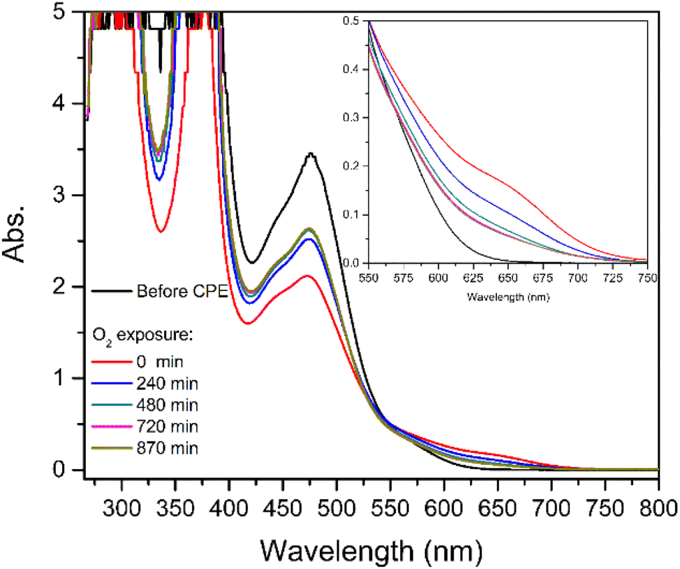 | ||
| Fig. 7 UV-vis spectra obtained for [1] after CPE under CO2 before and during exposure of the solution to atmospheric O2. | ||
Before electrolysis under CO2, the electronic spectrum of [1] is characterised by an intense band with a maximum at 476 nm (Fig. 7, black line). After electrolysis, a new shoulder at 657 nm is observed with the concomitant decrease of the intensity of the band at 476 nm (red line). After the solution was exposed to air (t > 0 min, Fig. 7) a decrease of the shoulder at 657 nm and an increase of the band at 476 nm were successively observed, confirming the regeneration of [1]. These observations are consistent with the formation of a relatively stable species, which disappears leading to the regeneration of [1]. Further discussion will be presented in the next section (Computational studies: the reaction with CO2).
EPR spectroscopy was also used to shed light on the species formed after CPE of [1] and before CO release. The EPR spectrum of [1] after CPE (Fig. 8) exhibits a signal characteristic of a S = 1/2 species, with gav ≈ 2.020 (g1,2,3 ≈ 2.065, 2.006, 1.990). This gav value clearly indicates that the unpaired electron is neither centred on the metal nor present in an “isolated” organic radical (since typical Ni(I) and Ni(III) complexes exhibit higher and more anisotropic g values (gav ≥ 2.13)44 and organic radicals give rise to isotropic, narrow signals centred around the free electron value, ge = 2.0023). Yet, the observed spectrum is consistent with an intermediate situation, where an organic-based radical species is under the (weak) influence of a transition metal. When the SOMO has contributions from the metal d orbitals, gav shifts from the free electron value and this shifting is proportional to the metal characteristic of the SOMO. Hence, the gav = 2.020 signal is consistent with [1] after CPE having a SOMO predominantly centred on the ligand, with a small contribution from the metal. The absence of visible hyperfine interactions (namely the triplet lines characteristic of I (N) = 1) suggests that this radical is not nitrogen-based. Overall, the EPR spectrum suggests that [1] holds a redox-active ligand that, after CPE, is converted into a nickel-coordinated phenoxyl radical. Such a species may derive from 3[Ni(I)(salphen˙)]2− referred above and will be further discussed below.
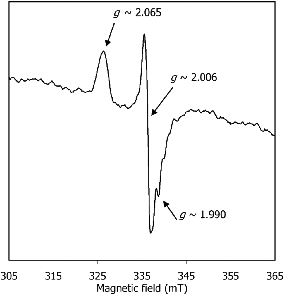 | ||
| Fig. 8 EPR spectrum of [1] after CPE under CO2, in DMF at 90 K. Spectrum was acquired as described in the Experimental section. | ||
Computational studies: the reaction with CO2
The reaction of Ni(salphen) complexes with CO2 described in the experimental studies above could in principle start with the 1- (2[1]−) or the 2-electron reduced (3[1]2−) complex. Both can bind CO2 (see below) and, as previously mentioned, formally contain Ni(I), as the second electron is localised in the ligand. However, the reduction potential at which the reaction starts is not consistent with the second reduction of the initial complex [1], although further reduction of new species may take place. On the other hand, neither the parent complex [1] nor 1[1]2− are able to bind CO2.In the very well-studied and efficient CO2 reduction catalyst [Ni(II)(cyclam)]2+, the active species is the Ni(I) one-electron reduced complex.31–34 On the other hand, this active species differs from 2[1]− due to the nature of the cyclam ligand. First, there are no low energy empty orbitals localised in a ligand and when reduction continues, Ni(0) species are formed and were detected.34 Second, cyclam can exist in several different conformations, while the rigidity of salphen prevents this possibility. Third, the Ni(II) precursor, [Ni(II)(cyclam)]2+, is a cation, while [Ni(II)salphen] [1] is neutral. These facts show how differently the two systems should behave, despite Ni(I) playing a central role in the reaction in both cases. Interestingly, Ni(0)(phen) derivatives catalysed the reductive carboxylation of alkyl and aryl halides with CO2 and the active species is a Ni(I)(phen) complex,50 highlighting the role of Ni(I) in CO2 activation.40
According to our DFT calculations, the carbon dioxide molecule approaches [1] or 1[1]2− with an increasing repulsion; therefore, no reaction occurs. On the other hand, 2[1]− and 3[1]2− are able to coordinate carbon dioxide as η1-CO2 to afford 2[1(CO2)]− and 3[1(CO2)]2−, respectively, with binding energies of 11.0 and 7.8 kcal mol−1. Attempts to obtain either the η1-OCO or η2-CO2 coordination mode failed. Calculations reported on the reduced [Ni(cyclam)]− complex showed that CO2 could coordinate to Ni(I) as both η1-CO2 and η1-OCO, but the η1-CO2 had a binding energy of 1.6 kcal mol−1, reproducing the experimental value, and was 14 kcal mol−1 more stable than the O-bound η1-OCO species.36
The reaction to reduce CO2 to the final product, CO, as detected experimentally (see above), involves two electrons and two protons, the other product being water.
| CO2 + 2H+ + 2e− → CO + H2O |
The reduction and protonation reactions may follow different paths, as represented in Fig. 9 (reductions in blue and protonations in red). According to voltammetry results (Fig. 2), the reaction starts with 2[1]−, the one-electron reduction product of Ni(salphen), [1], that binds CO2 (2[1(CO2)]−). This CO2 complex can then be further reduced to 3[1(CO2)]2−. The first proton will then add to the bound CO2, forming the 3[1(CO2H)]− intermediate with the HCO2 ligand, which decomposes into CO and H2O upon the addition of the second proton. CO remains coordinated to the metal centre. To close the cycle, the initial Ni(II) complex, 1[1], must be regenerated. This is one of the highlighted pathways (thick line) in Fig. 9. The other will be discussed afterwards.
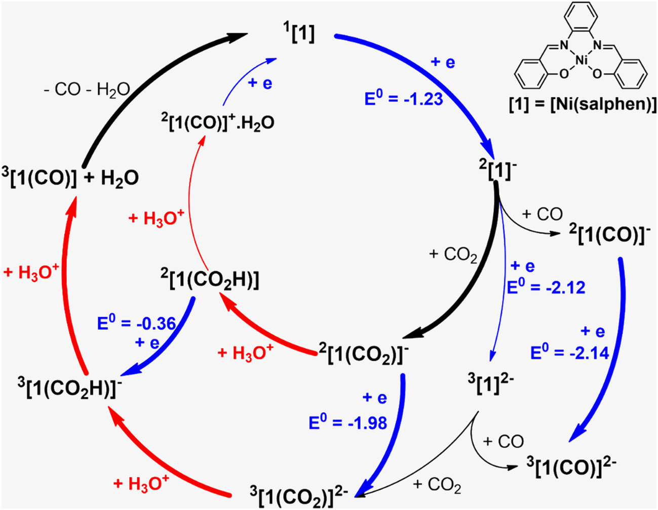 | ||
| Fig. 9 Pathways for CO2 reduction to CO in the presence of [Ni(salphen)], [1]. | ||
The Gibbs energy barrier for CO2 binding to 2[1]− as η1-CO2 (2[1(CO2)]−) was calculated as 11.5 kcal mol−1. In the corresponding transition state (TS), the Ni–C distance is 2.434 Å. The geometry of the Ni(salphen) fragment is barely perturbed since bond lengths and angles are very close to those in 2[1]−, but the C–O–C angle has narrowed from 180° in free CO2 to 157.8°, while the two C–O bonds have lengthened from 1.157 to 1.177 (Fig. 10). In the reaction of CO2 with 3[1]2− the barrier is slightly lower (10.6 kcal mol−1) and distances and angles in the TS are comparable. Previous studies of CO2 binding to Ni(I) in related complexes36 did not report transition states for this step.
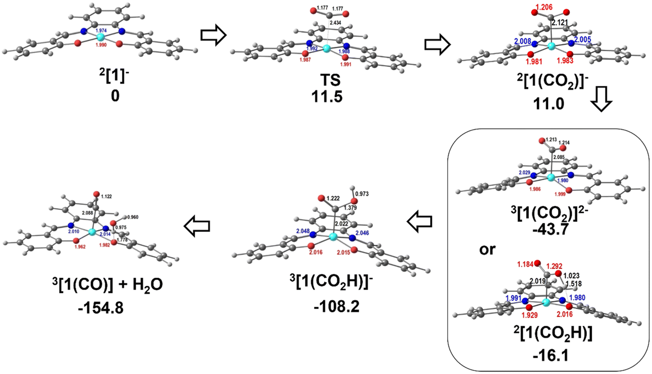 | ||
| Fig. 10 Optimised structures of the intermediates in CO2 binding to 2[1]− and reduction to CO: TS between 2[1]− and 2[1(CO2)]−, 3[1(CO2)]2− or 2[1(CO2H)], 3[1(CO2H)]−, and 3[1(CO)]+H2O. | ||
More distortions occur in the transformation of the transition state into the CO2 complex 2[1(CO2)]−. The metal achieves a square pyramidal environment, with this ligand occupying the apical position at a Ni–C distance of 2.121 Å. CO2 occupies a position very close to the plane bisecting the N–Ni–C angles, as also happened in the TS. Notice that after further reduction to 3[1(CO2)]2−, the square pyramid becomes less symmetric, with CO2 overlapping one of the N–Ni–O axes (Fig. 10). Since the coordination of CO2 requires distortion from a linear to an angular geometry, there are changes in the π orbitals, as shown schematically in the Walsh diagram of Fig. S17.† The most relevant one is the significant stabilisation of the LUMO π* in-the-plane of the CO2 molecule, which loses part of its antibonding character. The other π* orbital, initially degenerate, is not much affected by the distortion and its energy remains almost the same. This orbital can be stabilised by interaction with metal orbitals, namely dz2 and dxz, as is clearly shown in the Hβ-1 orbital of 3[1(CO2)]2− (Fig. S18†). The occupation of the π* CO2 orbital indicates that this molecule is partly reduced upon binding and therefore activated. The frontier orbitals of 3[1(CO2)]2− are shown in Fig. S18.†
It should be mentioned that the same intermediates, 2[1]− and 3[1]2−, may also bind CO with formation of more stable complexes, 2[1(CO)]− and 3[1(CO)]2− (Fig. 9); therefore, this should be a competitive process compared to binding CO2. But when the reaction starts there is no CO in the system so we can ignore it for the moment (CO binding will be addressed below).
The following steps involve protonation of the coordinated CO2 ligand. The first proton approaches from the top. The Ni–N,O bonds in 3[1(CO2H)]− become slightly longer and the orientation of the C–O–C fragment relative to the Ni(salphen) fragment has changed, as it now occupies a position close to its mirror plane (Fig. 10). The second protonation should yield a “CO2H2” ligand, but it spontaneously releases CO, which remains bonded to nickel and H2O. This water molecule stays hydrogen bonded to one of the salphen oxygen atoms, as depicted in 3[1(CO)]+H2O, Fig. 10. The distance between carbonyl C and water O is only 2.927 Å, and the Ni–C–O angle is 173.4°, very close to the expected linear coordination. After the two protonations, the metal has been oxidised back to Ni(II) and this intermediate (a local minimum) relaxes (6.7 kcal mol−1), releasing CO and water, via a spin transition to the initial Ni(II) complex 1[1]. When CO is present after the first cycle, 1[1] competes with CO2 to form preferentially CO complexes with 2[1]− or 3[1]2−. Both reactions occur without any barriers, as no maximum in a Ni–CO bond scan could be located, the potential being attractive. The geometry is also square pyramidal with CO in the apical position for both products. 3[1(CO)]2− is much more symmetric than the CO2 complex, with the CO bond almost in the mirror plane of the parent [1], the two C–Ni–N angles being ∼103–104° and the two C–Ni–O ∼94–96°. Surprisingly, the O–C–Ni angle is 127.5°, reflecting an unusual bent carbonyl coordination (Fig. 10). One of these metal carbonyl complexes will be the species identified by spectroscopic techniques when the reaction stops. No further reaction with CO2 occurs and the system is inactive. The energy profile for these processes is depicted in Fig. 10. The protonation of the coordinated CO2 is a highly exergonic process.
Alternative pathways were calculated starting with the one-electron reduction complex 2[1]1−, but changing the order of the other steps (inner circle and mixed circles in Fig. 9) after reaching 2[1(CO2)]−. Another likely competing mechanism (Fig. 10) proceeds by the protonation of 2[1(CO2)]− to afford the carbonyl complex 2[1(CO2H)] (highlighted in Fig. 9). It is reduced to 3[1(CO2H)]−, a species common to both pathways, at a less negative pathway than 2[1(CO2)]− (Fig. 10). In this mechanism, there is an initial reduction/protonation step, more in line with general mechanisms proposed for CO2-to-CO reduction.51
In the other possibility (path not highlighted in Fig. 9), the protonation product 2[1(CO2H)] would be further protonated to an unlikely 2[1(CO)]+·H2O (cationic CO complexes are rare) and reduced again in the final step. However, the two paths shown in thick lines in Fig. 9 seem the more likely to be consistent with the low potentials observed in the reaction with CO2. A general scheme of the reactions discussed is given in Fig. S19.†
Computational studies: spectroscopic studies (electronic absorption, vibrational, and EPR)
After proposing a mechanism for the reduction of CO2, the spectroscopic evidence (electronic absorption, vibrational, EPR) must be addressed. As described above (Electrochemical studies section), after the electrolysis under CO2 in the presence of an acid, to provide the electrons and the protons needed for reducing CO2, a coloured solution remains. CO is released from this solution under exposure to air or dioxygen. We showed that as soon as CO starts to be formed, both 2[1]− and 3[1]2− can bind CO to the metal, competing very effectively with CO2. Considering that the reaction starts after the first reduction, it is more likely that the CO released is captured by the one-electron reduced complex 2[1]− to yield 2[1(CO)]− (Fig. 9) and eventually further reduced to 3[1(CO)]2−. There is another species formed during the initial reaction with CO2, 3[1(CO)]+H2O, which also contains CO. This is a paramagnetic Ni(II) complex. Therefore, the metal carbonyl complex could be 2[1(CO)]−, 3[1(CO)]2−, or less likely 3[1(CO)]+H2O. The experimental evidence derived from the IR-SEC, UV-visible absorption and EPR spectroscopy, combined with the DFT calculations of the three kinds of spectra allows us to identify the CO complex.Frequency calculations on the energy minima provided the easily identified CO stretching frequencies, which were compared with the experimental data. The CO stretching frequency determined from the SEC-IR experiments was 1935 cm−1. The calculated values are 1882 cm−1 for 3[1(CO)]2−, 1977 cm−1 for 2[1(CO)]−, and 2270 cm−1 for 3[1(CO)]+H2O. The frequency calculated for 3[1(CO)]2− is very close to the experimental value, without applying a scale factor. A scale factor of 0.97 leads to perfect agreement. Reported vibrational scaling factors are in the range 0.8–1.0,52 therefore making the other two intermediates very unlikely, since the calculated values are larger than the experimental ones. TDDFT calculations led to the obtention of the UV-visible absorption spectrum of 3[1(CO)]2−, 2[1(CO)]−, and 3[1(CO)]+H2O. The low energy band in the UV-visible absorption spectrum of [1], also calculated to calibrate the method, has a maximum at 476 nm and corresponds to the excitation calculated at 428 nm and 406 nm (Table S1 and Fig. S20†). The agreement is reasonable and these transitions have a LMCT/ILCT character, with a very small amount of d–d (HOMO and LUMO+1), since the HOMO−1 and LUMO are ligand based and the LUMO+1 has a small metal characteristic. Only the HOMO can be considered a “d” orbital (Fig. S2†).
The experimental absorption spectrum obtained after electrolysis (Fig. 7) showed the appearance of a new shoulder at 646 nm with a concomitant decrease of the intensity of the band at 476 nm. The spectrum calculated by TDDFT (Table 2) for 3[1(CO)]2− agrees very well with this scenario. As can be seen in Fig. 11, the agreement is excellent, with a good reproduction of all the features, despite the small wavelength shift. Indeed, new weak excitation is calculated in the low energy region (>600 nm region). The new excitation at 754 nm is attributed to the shoulder at 646 nm and the excitation calculated at 557, 553 and 550 nm correspond to the band centred at ∼472 nm in the experimental spectrum. The calculated spectra of the alternative 2[1(CO)]− and 3[1(CO)]+H2O are very different, since they lack any well-defined band in the visible and therefore do not reproduce the experimental curve (Fig. S21 and S22†).
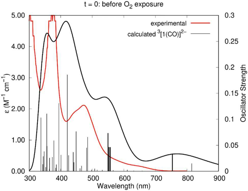 | ||
| Fig. 11 Experimental spectrum of the Ni(I)–CO species (red line) and calculated (TDDFT) spectrum of 3[1(CO)]2− (black line) in DMF. The sticks correspond to the calculated wavelengths. The details of those in bold are given in Table 2. | ||
| λ (nm) | f | Composition | λ exp (nm) |
|---|---|---|---|
| 754 | 0.0338 | Hβ → L+2β (72%) | 646 |
| 557 | 0.0461 | H−1α → Lα (30%), Hα → L+1α (26%), H−3α → Lα (7%), H−2β → Lβ (8%) | |
| 553 | 0.0464 | H−2α → Lα (45%), H−1α → Lα (15%), Hα → L+1α (16%) | 472 |
| 550 | 0.0733 | H−1α → Lα (22%), HαL+1α (22%), H−2β → Lβ (7%) |
EPR spectra of 3[1(CO)]2−, 2[1(CO)]−, and 3[1(CO)]+H2O were also calculated using the ADF program (see Computational details section).532[1(CO)]− exhibits that the value of g (2.161) most deviated from the experimental one (2.020). The two species 3[1(CO)]2− and 3[1(CO)]+H2O have g values closer to the experimental one, with 2.086 and 2.065, respectively. However, 3[1(CO)]+H2O was excluded by both the CO stretching frequency and the absorption spectrum, which did not reproduce the experimental one. Therefore, EPR spectroscopy, together with electronic absorption and vibrational data, helps to identify 3[1(CO)]2− as the metal carbonyl species.
Computational studies: the reaction with dioxygen and CO release
As has been shown experimentally, the metal carbonyl complex remains in solution until CO is released by exposure to air or dioxygen and it has been identified on spectroscopic grounds to be 3[1(CO)]2−. The DFT calculations show that when one molecule of O2 approaches 3[1(CO)]2−, CO is released and a dioxygen complex 3[1(O2)]2− is formed. Double protonation affords hydrogen peroxide and the initial Ni(II) complex, [Ni(salphen)], [1]. These reactions are depicted in Fig. 12.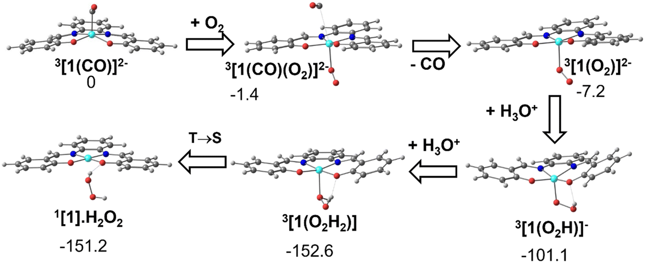 | ||
| Fig. 12 Conversion of the CO complex 3[1(CO)]2− into the initial complex [1] by reaction with O2 and double protonation (structures and relative Gibbs energies in kcal mol−1). | ||
The dioxygen approaches the complex on the empty side of the square pyramidal 3[1(CO)]2− and bonds to the Ni(I) metal centre. In 3[1(CO)(O2)]2−, Ni–O 2.199 Å, while the Ni–C bond has lengthened (3.261 Å is no longer a bonding distance). The O2 unit coordinates in 3[1(CO)(O2)]2− in a typical bent mode, with a O–O distance of 1.314 Å, much longer than the same distance in free dioxygen, and indicates that it can be considered superoxide (O2−). The spontaneous release of CO observed in the calculation stems from the fact that the metal loses one electron and therefore, there is much less back donation from Ni to CO, the Ni–CO bond becoming much weaker.
As the fragment Ni(I)salphen in 3[1(O2)]2− now has a −1 charge, the salphen ligand has been oxidised (remember that the second reduction of [1] occurred in the ligand), while the metal remains Ni(I). Upon the first protonation, the O–O distance reaches 1.453 Å, characteristic of hydroperoxide (OOH−). The global charge in the 3[1(O2H)]− product is now −1 and the metal was formally oxidised to Ni(II). The second protonation converts hydroperoxide in neutral H2O2. Ni(II) remains in the triplet state in the complex 3[1]. Spin crossover from 3[1] to 1[1] regenerates the initial complex (Fig. 9). This transformation is exergonic, as shown in Fig. 12.
The full pathway starts from the reaction of the reduced 2[1]− complex with CO2 (blue circle in Fig. S20†), followed by one protonation, one reduction (or coupled reduction/protonation) and a second protonation, and regenerates [1]. Since there is now CO in the system, 2[1]−, formed again after reduction, picks up CO (turquoise circle in Fig. S23†), yielding the CO complex 2[1(CO)]−, which is further reduced (identified experimentally as the final CO complex). In the presence of dioxygen, the reaction continues to [1]. Although all steps seem to go downhill, the initial electrochemical reduction of [1] provides the energy drive for the reaction.
Although the calculations were performed for complex [1], the similarity of the frontier orbitals of complexes [2] and [3] (Fig. S3 and S4†) suggests that the same mechanism may be acceptable. In the binuclear [3] (Fig. S4†), there are two different Ni(II) environments. The LUMO of neutral [3] is localised in the ligand, but the LUMO+4 orbital is metal-based and easily accessible since the energies of these frontier orbitals are similar and their order varies upon reduction. The twice reduced anion of [2], 3[2]2−, in the triplet state, has the first unpaired electron in the LUMO and the second in the ligand based one, exactly like [1]. The complex [2] undergoes reduction but the reactivity (decomposition) will depend on different steric and electronic factors.
We can also stress that the Ni(salphen) system reduces CO2 to CO, as the widely studied [Ni(cyclam)]2+ complex, among others, does, but with many differences. In the Ni(cyclam) system, CO is released spontaneously at the end of the reaction, the gas being immediately detected by gas chromatography; however in the presence of a scavenger the catalytic rate increases.31–34,36 In the Ni(salphen) system, however, the CO remains coordinated after CO2 reduction. As soon as CO is released, the active intermediate 2[1]− can bind either CO or CO2, but binding CO is much preferred (Fig. 12), and the complex is inactive. In mechanistic terms, [Ni(salphen)] requires a 2-electron reduction to complete the reaction, while other systems work after a one-electron reduction, as was discussed above. Still, the active species in CO2 activation is formally a Ni(I) complex as in the other reported systems.
Conclusions
The two complexes [Ni(II)(R-salphen)], [1] and [2] and the binuclear [3] are able to reduce CO2 to CO. Cyclic voltammetry and electrolysis experiments with gas chromatography analysis demonstrated that it is easier to reduce CO2 with [3] (Eonset = −1.43 V) than with [1] (Eonset = −1.60 V), while the reaction takes place at a much more negative potential with [2] (Eonset = −1.80 V). The conversion of CO2 was improved by the presence of water as the proton source. Although CO was not observed at the end of the reaction, it was detected after exposure to air or O2 of the final solution, probably containing a Ni(I)–CO species. SEC-IR experiments, wherein a potential was applied to a CO2 saturated solution of [1], revealed a new peak at 1935 cm−1 of the vibrational spectrum, characteristic of a terminally metal bound CO group. The EPR spectrum could be assigned to a Ni(I)salphen delocalised orbital.DFT calculations on [Ni(II)(salphen)] [1] addressed the one-electron and two-electron reduced species and their reactivity towards CO2 reduction. Both can be considered Ni(I) complexes, as the first reduction occurs in an orbital with 47% Ni characteristic, normal for a metal–ligand orbital (2[1]−) and the second in the ligand (3[1]2−). The latter, 3[1]2−, may thus also be considered a Ni(I) complex and represented as 3[Ni(I)(salphen˙)]2−, to emphasise that one of the electrons occupies a ligand orbital. Both 2[1]− and 3[1]2− bind CO2, but experimental data suggest that only 2[1]− is present when the reaction starts, though new species may be reduced. The reaction is initiated by the binding of CO2 to 2[1]− (2[1(CO2)]−), further reduction to 3[1(CO2)]2−, followed by two protonation steps affording the paramagnetic Ni(II)–CO complex 3[1(CO)]+H2O. Alternatively, 2[1(CO2)]− can be protonated to 2[1(CO2H)], and further reduction to 3[1(CO2H)]−, allows merging of the two mechanisms. The final 3[1(CO)]+H2O species releases CO and regenerates the initial complex [1]. Once CO is present in the reaction medium after the first cycle, it competes with CO2, forming the 2[1(CO)]−, which is further reduced to 3[1(CO)]2−, the metal–carbonyl species (spectroscopic and DFT identification). This competitive reaction kills the reaction hampering further CO2 reactivity. 3[1(CO)]2− reacts with dioxygen, releasing CO, to regenerate [1]. The apparently similar [Ni(cyclam)]2+ reacts with CO2 when it is reduced to Ni(I), but further reduction converts it into Ni(0), since there are no low energy ligand-based orbitals, and the catalytic cycle proceeds. Reactions with [1] are complicated by spin changes when compared to [Ni(cyclam)]2+.
Experimental
General considerations
All complexes were synthesised according to the literature.42,43 UV-vis spectra were recorded on a Shimadzu 50/60 Hz spectrometer using the electrolyte before and after bulk electrolysis experiments.Electrochemical procedures
Cyclic voltammetry experiments were performed in a three-electrode electrochemical double-wall jacketed cell thermostated by circulation of water with the reference electrode separated by a glass frit. Glassy carbon (3 mm diameter, custom made) and platinum wire were used as working and counter electrodes, respectively. Saturated calomel electrode (SCE = −0.241 V vs. NHE) was used as the reference electrode and tetrabutylammonium hexafluorophosphate (TBAPF6) as the supporting electrolyte (electrochemical grade). The ohmic drop was compensated by a positive feedback present in the instrument. The working electrode was polished with diamond paste of several diameter sizes (15, 6, 3 and 1 μm) and washed thoroughly with Milli-Q water and dried under a nitrogen flux. Controlled-potential electrolysis experiments were carried out using an electrochemical cell with a glassy carbon plate (3 cm2) as working electrode, SCE as reference and a platinum grid as counter electrode. The ohmic drop was minimised by directly immersing the reference electrode in the solution (catholyte, 5 mL) while the counter electrode (platinum grid) was placed in a separated compartment (anolyte, 3 mL) separated by a glass frit. Additionally, 0.2 M tetraethylammonium acetate was added into the anodic compartment for electron compensation of the reaction occurring at the cathodic compartment (CO2 reduction). All experiments were accomplished using an AUTOLAB PGSTAT128N potentiostat (Metrohm) controlled by NOVA software.SEC-IR experiments were performed using a cell acquired from LabOmak. This cell has two platinum grids as working and counter electrodes and an Ag wire as the pseudo-reference electrode. A CO2 saturated DMF solution with 5 mM [1] and 0.1 M TBAPF6 was injected in the SEC-IR cell. A linear voltammogram was performed using a scan rate of 10 mV s−1 to reach the suitable potential. The IR spectra were obtained using a Nicolet 6700 FTIR spectrophotometer with a resolution of 4 cm−1, mirror velocity of 0.3165, aperture 32, gain 4 with 16 scans between 2200–1780 cm−1. The background spectrum was performed with the sample at the open circuit potential. All spectra were smoothed using a Savitzky–Golay algorithm with 15 data points.
UV-vis was used to detect hydrogen peroxide after the bulk electrolysis. Milli-Q was added (approx. 2.5 mL) to a 200 μL aliquot of the electrolysis. The solution was filtered and analysed by UV-vis before and after the addition of an Fe(II) aqueous solution (1 mM, 600 μL).
Gas quantification
Analyses from the gas evolved in the headspace during electrolysis were performed with an Agilent Technologies 7820A GC system equipped with a thermal conductivity detector. CO and H2 production were quantitatively assessed using a CP-CarboPlot P7 capillary column (27.46 m in length and 25 μm internal diameter). Temperature was held at 150 °C for the detector and 34 °C for the oven. The carrier gas was argon flowing at 9.5 mL min−1 at a constant pressure of 0.5 bars. Injection was performed via a 250 μL gas-tight syringe (Hamilton). These conditions allowed for the separation of both H2, O2, N2, CO, and CO2. Calibration curves for H2 and CO were determined separately by injecting known quantities of pure gas.EPR spectroscopy
X-band EPR spectra were acquired using a Bruker EMX 6/1 spectrometer and a dual mode ER4116DM rectangular cavity (Bruker). The sample was cooled with liquid helium using an Oxford Instruments ESR900 continuous-flow cryostat, fitted with a temperature controller. Spectra were acquired at 90 K, with a modulation frequency of 100 kHz. Different modulation amplitudes and microwave power values (0.1–1.0 mT and 2 to 63 mW) were tested to guarantee that the signal was not saturated, and potential fine structure is observable. No other signals were observed between 10 and 600 mT. Spectrum shown was acquired with 0.1 mT and 20 mW.Computational details
Density functional theory (DFT) calculations41 were performed with the Gaussian09 package.49 The PBE1PBE functional, also known as PBE0,32 which combines the generalised gradient functional of Perdew, Burke and Ernzerhof (PBE)54,55 with a predefined amount of exact exchange functional defined by Adamo and Barone48 was employed. For nickel, the triple-ζ basis set with one polarisation function LANL2TZ(f) together with the associated effective core potential (ECP) was used56 downloaded from the EMSL Basis Set Library.57,58 All the other elements were represented with the 6-311G** basis set. The geometries of all intermediates and transition states were optimised without symmetry constraints. To check the nature of the stationary points, in the case of transition state structures, the connecting reagents and products were checked by following the reaction path by integrating the intrinsic reaction coordinate (IRC calculation). In all calculations, the solvent effects (DMF) were accounted using a polarisable continuum model (PCM) via the integral equation formalism variant (IEFPCM). To calculate redox potentials, the free energies of the parent and reduced species were considered (absolute) and corrected for SCE using a shift of −4.350 V as reported by Isse and Gennaro.59 For protonation energies, H3O+ was used as the proton source. TDDFT calculations were performed using the same functional and basis sets on the optimised geometries. The GaussSum60 and the MultiWfn61 packages were used to analyse and calculate the localization of molecular orbitals in different atoms, the orbital contributions to each excitation and to generate the simulated UV-vis spectra. Structures were drawn using Chemcraft62 and the orbitals with Molekel.63The EPR spectra were calculated with the Amsterdam density functional (ADF) program,53 using the Vosko–Wilk–Nusair64 local density approximation of the correlation energy and the PBE0 functional, as above. Solvent effects (DMF) were considered using the COSMO model implemented in ADF. Scalar and spin orbit relativistic effects were described with the ZORA approximation.65 Triple ζ Slater-type orbitals (STO) were used to describe all the electrons of H, C, O, N, and Ni, augmented with two sets of polarization functions (ADF T2ZP basis set). Unrestricted calculations were carried out for open shell complexes.
Conflicts of interest
There are no conflicts to declare.Acknowledgements
The authors thank Fundação para a Ciência e a Tecnologia (FCT), Portugal, for projects UIDB/04046/2020 and UIDP/04046/2020 (BioISI), UIDB/50006/2020 and UIDP/50006/2020 (REQUIMTE), and PTDC/BTA-BTA/0935/2020 (LBM). Centro de Química Estrutural (CQE) and Institute of Molecular Sciences (IMS) acknowledge the financial support of Fundação para a Ciência e Tecnologia (Projects UIDB/00100/2020, UIDP/00100/2020, and LA/P/0056/2020, respectively). The NMR spectrometers are part of the National NMR Network (PTNMR) and are partially supported by Infrastructure Project No 022161 (co-financed by FEDER through COMPETE 2020, POCI and PORL and FCT through PIDDAC). FCT is acknowledged for IF/00069/2014 (PJC), SFRH/BSAB/135473/2017 (MJC) and PTDCQUI-QIN0252_2021 (PNM), and also the Individual Call to Scientific Employment Stimulus contracts CEECIND/00509/2017 (PNM), 2020.02134.CEECIND (SR), 2021.00381.CEECIND (PJC). The CARISMA COST action CM1205 is acknowledged. MJC thanks N. A. G. Bandeira for technical assistance. The CATSUS doctoral programme is also acknowledged.References
- M. Aresta, My Journey in the CO2-Chemistry Wonderland, Coord. Chem. Rev., 2016, 334, 150–183 CrossRef.
- N. J. English, M. M. El-Hendawy, D. A. Mooney and J. M. D. MacElroy, Perspectives on Atmospheric CO2 Fixation in Inorganic and Biomimetic Structures, Coord. Chem. Rev., 2014, 269, 85–95 CrossRef CAS.
- S. B. Jiménez-Pulido, N. A. Illán-Cabeza, F. Hueso-Ureña, C. R. Maldonado, P. Sánchez-Sánchez, M. P. Fernández-Liencres, M. Fernández-Gómez and M. N. Moreno-Carretero, A combined experimental and DFT investigation on the structure and CO-releasing properties of mono and binuclear fac-ReI(CO)3 complexes with 5-pyridin-2-ylmethylene-amino uracils, Dalton Trans., 2016, 45, 15142–15154 RSC.
- M. Chaves-Ferreira, I. S. Albuquerque, D. Matak-Vinkovic, A. C. Coelho, S. M. Carvalho, L. M. Saraiva, C. C. Romão and G. J. L. Bernardes, Spontaneous CO Release from RuII(CO)2-Protein Complexes in Aqueous Solution, Cells, and Mice, Angew. Chem., Int. Ed., 2015, 54, 1172–1175 CrossRef CAS PubMed.
- S. García-Gallego and G. J. L. Bernardes, Carbon-Monoxide-Releasing Molecules for the Delivery of Therapeutic CO In Vivo, Angew. Chem., Int. Ed., 2014, 53, 9712–9721 CrossRef PubMed.
- X. Zhang, H. Su, Y. Zhang and X. Gu, Effect of CeO2 promotion on the catalytic performance of Co/ZrO2 catalysts for Fischer–Tropsch synthesis, Fuel, 2016, 184, 162–168 CrossRef CAS.
- X. Wu, X. Fang, L. Wu, R. Jackstell, H. Neumann and M. Beller, Transition-Metal-Catalyzed Carbonylation Reactions of Olefins and Alkynes: A Personal Account, Acc. Chem. Res., 2013, 47, 1041–1053 CrossRef PubMed.
- J. Hong, W. Zhang, J. Ren and R. Xu, Photocatalytic reduction of CO2: A brief review on product analysis and systematic methods, Anal. Methods, 2013, 5, 1086–1097 RSC.
- J. Qiao, Y. Liu, F. Hong and J. Zhang, A review of catalysts for the electroreduction of carbon dioxide to produce low-carbon fuels, Chem. Soc. Rev., 2014, 43, 631–675 RSC.
- J. Bonin, A. Maurin and M. Robert, Molecular Catalysis of the Electrochemical and Photochemical Reduction of CO2 with Fe and Co Metal Based Complexes. Recent Advances, Coord. Chem. Rev., 2016, 334, 184–198 CrossRef.
- A. M. Appel, J. E. Bercaw, A. B. Bocarsly, H. Dobbek, D. L. Dubois, M. Dupuis, J. G. Ferry, E. Fujita, R. Hille, P. J. A. Kenis, C. A. Kerfeld, R. H. Morris, C. H. F. Peden, A. R. Portis, S. W. Ragsdale, T. B. Rauchfuss, J. N. H. Reek, L. C. Seefeldt, R. K. Thauer and G. L. Waldrop, Frontiers, Opportunities, and Challenges in Biochemical and Chemical Catalysis of CO2 Fixation, Chem. Rev., 2013, 113, 6621–6658 CrossRef CAS PubMed.
- J. L. Inglis, B. J. MacLean, M. T. Pryce and J. G. Vos, Electrocatalytic Pathways Towards Sustainable Fuel Production from Water and CO2, Coord. Chem. Rev., 2012, 256, 2571–2600 CrossRef CAS.
- G. Centi, E. A. Quadrelli and S. Perathoner, Catalysis for CO2 Conversion: A Key Technology for Rapid Introduction of Renewable Energy in the Value Chain of Chemical Industries, Energy Environ. Sci., 2013, 6, 1711 RSC.
- M. Peer, S. Mehdi Kamali, M. Mahdeyarfar and T. Mohammadi, Separation of Hydrogen from Carbon Monoxide Using a Hollow Fiber Polyimide Membrane: Experimental and Simulation, Chem. Eng. Technol., 2007, 30, 1418–1425 CrossRef CAS.
- S. Tada and R. Kikuchi, Mechanistic Study and Catalyst Development for Selective Carbon Monoxide Methanation, Catal. Sci. Technol., 2015, 5, 3061–3070 RSC.
- B. Miao, S. S. K. Ma, X. Wang, H. Su and S. H. Chan, Catalysis Mechanisms of CO2 and CO Methanation, Catal. Sci. Technol., 2016, 6, 4048–4058 RSC.
- I. H. Kim, H. O. Seo, E. J. Park, S. W. Han and Y. D. Kim, Low Temperature CO Oxidation over Iron Oxide Nanoparticles Decorating Internal Structures of a Mesoporous Alumina, Sci. Rep., 2017, 7, 40497 CrossRef CAS PubMed.
- D. Britt, D. Tranchemontagne and O. M. Yaghi, Metal-organic frameworks with high capacity and selectivity for harmful gases, Proc. Natl. Acad. Sci. U. S. A., 2008, 105, 11623–11627 CrossRef CAS PubMed.
- E. Barea, C. Montoro and J. A. R. Navarro, Toxic Gas Removal - Metal-Organic Frameworks for the Capture and Degradation of Toxic Gases and Vapours, Chem. Soc. Rev., 2014, 43, 5419–5430 RSC.
- V. Van Speybroeck, K. Hemelsoet, L. Joos, M. Waroquier, R. G. Bell, C. Richard and A. Catlow, Advances in Theory and their Application within the Field of Zeolite Chemistry, Chem. Soc. Rev., 2015, 44, 7015–7430 RSC.
- S. Sircar, T. C. Golden and M. B. Rao, Activated Carbon for Gas Separation and Storage, Carbon, 1996, 34, 1–12 CrossRef CAS.
- E. D. Park, D. Lee and H. C. Lee, Recent Progress in Selective CO Removal in a H2-Rich Stream, Catal. Today, 2009, 139, 280–290 CrossRef CAS.
- D. A. Reed, D. J. Xiao, M. I. Gonzalez, L. E. Darago, Z. R. Herm, F. Grandjean and J. R. Long, Reversible CO Scavenging via Adsorbate-Dependent Spin State Transitions in an Iron(II)-Triazolate Metal-Organic Framework, J. Am. Chem. Soc., 2016, 138, 5594–5602 CrossRef CAS PubMed.
- E. D. Bloch, M. R. Hudson, J. A. Mason, S. Chavan, V. Crocellà, J. D. Howe, K. Lee, A. L. Dzubak, W. L. Queen, J. M. Zadrozny, S. J. Geier, L. C. Lin, L. Gagliardi, B. Smit, J. B. Neaton, S. Bordiga, C. M. Brown and J. R. Long, Reversible CO Binding Enables Tunable CO/H2 and CO/N2 Separations in Metal-Organic Frameworks with Exposed Divalent Metal Cations, J. Am. Chem. Soc., 2014, 136, 10752–10761 CrossRef CAS PubMed.
- B. E. Mann, CO-Releasing, Molecules: A Personal View, Organometallics, 2012, 31, 5728–5735 CrossRef CAS.
- J. M. Smieja, M. D. Sampson, K. A. Grice, E. E. Benson, J. D. Froehlich and C. P. Kubiak, Manganese as a Substitute for Rhenium in CO2 Reduction Catalysts: The Importance of Acids, Inorg. Chem., 2013, 52, 2484–2491 CrossRef CAS PubMed.
- C. W. Machan, M. D. Sampson and C. P. Kubiak, A Molecular Ruthenium Electrocatalyst for the Reduction of Carbon Dioxide to CO and Formate, J. Am. Chem. Soc., 2015, 137, 8564–8571 CrossRef CAS PubMed.
- M. Bourrez, F. Molton, S. Chardon-Noblat and A. Deronzier, [Mn(bipyridyl)(CO)3Br]: An Abundant Metal Carbonyl Complex as Efficient Electrocatalyst for CO2 Reduction, Angew. Chem., Int. Ed., 2011, 50, 9903–9906 CrossRef CAS PubMed.
- X. Cui, S. Liu, L. Zhao, J. Yu, S. Ling, Y. Zhao, J. Wang, W. Qin, X. Mao and J. Zhang, Modulating Carbon Dioxide Activation on Carbon Nanotube Immobilized Salophen Complexes by Varying Metal Centers for Efficient Electrocatalytic Reduction, J. Colloid Interface Sci., 2022, 608, 1827–1836 CrossRef CAS PubMed.
- H. Louis, O. U. Akakuru, P. Monday and O. O. Funmilayo, A Review on the State-of-the-Art Advances for CO Electro-Chemical Reduction using Metal Complex Molecular Catalysts, Ecletica Quim., 2019, 44, 11–39 CrossRef CAS.
- M. Beley, J.-P. Collin, R. Ruppert and J.-P. Sauvage, Nickel(II)-Cyclam: An Extremely Selective Electrocatalyst for Reduction of CO2 in Water, J. Chem. Soc., Chem. Commun., 1984, 1315–1316 RSC.
- M. Beley, J.-P. Collin, R. Ruppert and J.-P. Sauvage, Electrocatalytic Reduction of CO2 by Ni Cyclam2+ in Water: Study of the Factors Affecting the Efficiency and the Selectivity of the Process, J. Am. Chem. Soc., 1986, 108, 7461–7467 CrossRef CAS PubMed.
- J. D. Froehlich and C. P. Kubiak, Homogeneous CO2 Reduction by Ni(cyclam) at a Glassy Carbon Electrode, Inorg. Chem., 2012, 51, 3932–3934 CrossRef CAS PubMed.
- J. D. Froehlich and C. P. Kubiak, The Homogeneous Reduction of CO2 by [Ni(cyclam)]+: Increased Catalytic Rates with the Addition of a CO Scavenger, J. Am. Chem. Soc., 2015, 137, 3565–3573 CrossRef CAS PubMed.
- S. L. Behnke, A. C. Manesis and H. S. Shafaat, Spectroelectrochemical Investigations of Nickel Cyclam Indicate Different Reaction Mechanisms for Electrocatalytic CO2 and H+ Reduction, Dalton Trans., 2018, 47, 15206–15216 RSC.
- J. Song, E. L. Klein, F. Neese and S. Ye, The Mechanism of Homogeneous CO2 Reduction by Ni(cyclam): Product Selectivity, Concerted Proton-Electron Transfer and C-O Bond Cleavage, Inorg. Chem., 2014, 53, 7500–7507 CrossRef CAS PubMed.
- P. Gerschel, B. Battistella, D. Siegmund, K. Ray and U.-P. Apfel, Electrochemical CO2 Reduction - The Effect of Chalcogenide Exchange in Ni-Isocyclam Complexes, Organometallics, 2020, 39, 1497–1510 CrossRef CAS.
- T. Fogeron, T. K. Todorova, J.-P. Porcher, M. Gomez-Mingot, L.-M. Chamoreau, C. Mellot-Draznieks, Y. Li and M. Fontecave, A Bioinspired Nickel(bis-dithiolene) Complex as a Homogeneous Catalyst for Carbon Dioxide Electroreduction, ACS Catal., 2018, 8, 2030–2038 CrossRef CAS.
- C. Yoo, Y.-E. Kim and Y. Lee, Selective Transformation of CO2 to CO at a Single Nickel Center, Acc. Chem. Res., 2018, 51, 1144–1152 CrossRef CAS PubMed.
- D. Oren, Y. Diskin-Posner, L. Avram, M. Feller and D. Milstein, Metal–Ligand Cooperation as Key in Formation of Dearomatized NiII–H Pincer Complexes and in Their Reactivity toward CO and CO2, Organometallics, 2018, 37, 2217–2221 CrossRef CAS PubMed.
- R. G. Parr and W. Yang, Density-Functional Theory of Atoms and Molecules, Oxford University Press, Inc., New York, 1st edn, 1989 Search PubMed.
- S. Realista, A. S. Viana, B. de P. Cardoso, A. M. Botelho do Rego, P. D. Vaz, A. I. Melato, P. N. Martinho and M. J. Calhorda, Asymmetric Binuclear Ni(II) and Cu(II) Schiff Base Metallopolymers, RSC Adv., 2015, 5, 39495–39504 RSC.
- S. Realista, P. Ramgi, B. de P. Cardoso, A. I. Melato, A. S. Viana, M. J. Calhorda and P. N. Martinho, Heterodinuclear Ni(II) and Cu(II) Schiff Base Complexes and their Activity in Oxygen Reduction, Dalton Trans., 2016, 45, 14725–14733 RSC.
- F. Azevedo, C. Freire and B. Castro, Reductive electrochemical study of Ni(II) complexes with N2O2 Schiff base Complexes and Spectroscopic Characterisation of the Reduced Species. Reactivity towards CO, Polyhedron, 2002, 21, 1695–1705 CrossRef CAS.
- A. A. Isse, A. Gennaro and E. Vianello, A Study of the Electrochemical Reduction Mechanism of Ni(Salophen) in DMF, Electrochim. Acta, 1992, 37, 113–118 CrossRef CAS.
- S. Gambarotta, F. Urso, C. Floriani, A. Chiesi-Villa and C. Guastini, Carbon-Carbon Bond Forming and Breaking by a Metal-Assisted Redox Process in a Nickel(II)-Schiff Base Complex, Inorg. Chem., 1983, 22, 3966–3972 CrossRef CAS.
- C. Costentin, S. Drouet, M. Robert and J.-M. Saveant, A Local Proton Source Enhances CO2 Electroreduction to CO by a Molecular Fe Catalyst, Science, 2012, 338, 90–94 CrossRef CAS PubMed.
- C. Adamo and V. Barone, Toward reliable density functional methods without adjustable parameters: The PBE0 model, J. Chem. Phys., 1999, 110, 6158–6170 CrossRef CAS.
- M. J. Frisch, G. W. Trucks, H. B. Schlegel, G. E. Scuseria, M. A. Robb, G. Cheeseman, J. R. Scalmani, V. Barone, B. Mennucci, G. A. Petersson, H. Nakatsuji, M. Caricato, X. Li, H. P. Hratchian, A. F. Izmaylov, J. Bloino, G. Zheng, J. L. Sonnenberg, M. Hada, M. Ehara, K. Toyota, R. Fukuda, J. Hasegawa, M. Ishida, T. Nakajima, Y. Honda, O. Kitao, H. Nakai, T. Vreven, J. A. Montgomery, Jr., J. E. Peralta, F. Ogliaro, M. Bearpark, J. J. Heyd, E. Brothers, K. N. Kudin, V. N. Staroverov, R. Kobayashi, J. Normand, K. Raghavachari, A. Rendell, J. C. Burant, S. S. Iyengar, J. Tomasi, M. Cossi, N. Rega, N. J. Millam, M. Klene, J. E. Knox, J. B. Cross, V. Bakken, C. Adamo, J. Jaramillo, R. Gomperts, R. E. Stratmann, O. Yazyev, A. J. Austin, R. Cammi, C. Pomelli, J. W. Ochterski, R. L. Martin, K. Morokuma, V. G. Zakrzewski, G. A. Voth, P. Salvador, J. J. Dannenberg, S. Dapprich, A. D. Daniels, Ö. Farkas, J. B. Foresman, J. V. Ortiz, J. Cioslowski and D. J. Fox, Gaussian 09, Gaussian, Inc., Wallingford CT, 2009 Search PubMed.
- P. Vadivelu and K. Ganesan, Density Functional Theory Study on [Ni0(1,10-Phenanthroline)]-Catalyzed Reductive Carboxylation of Alkyl and Aryl Halides with CO2: Effect of the Lewis Acid and β-H Elimination Side Reaction in the Crucial CO2 Insertion Step, Inorg. Chem., 2022, 61, 19463–19474 CrossRef CAS PubMed.
- M. Tarrago and S. Ye, A Short Perspective on Electrochemical CO2 Reduction to CO, Chimia, 2020, 74, 478–482 CrossRef CAS PubMed.
- NIST Computational Chemistry Comparison and Benchmark Database NIST Standard Reference Database Number 101, Release 19, April 2018, ed. Russell D. Johnson III, https://cccbdb.nist.gov/, DOI:10.18434/T47C7Z.
- (a) G. te Velde, F. M. Bickelhaupt, S. J. A. van Gisbergen, C. Fonseca Guerra, E. J. Baerends, J. G. Snijders and T. Ziegler, Chemistry with ADF, J. Comput. Chem., 2001, 22, 931–967 CrossRef CAS; (b) C. Fonseca Guerra, J. G. Snijders, G. te Velde and E. J. Baerends, Towards an order-N DFT method, Theor. Chem. Acc., 1998, 99, 391–403 Search PubMed; (c) ADF2013, SCM, Theoretical Chemistry, Vrije Universiteit, Amsterdam, The Netherlands, https://www.scm.com Search PubMed.
- (a) J. P. Perdew, Density-Functional Approximation for the Correlation Energy of the Inhomogeneous Electron Gas, Phys. Rev. B: Condens. Matter Mater. Phys., 1986, 33, 8822–8824 CrossRef PubMed; (b) J. P. Perdew, Erratum, Phys. Rev. B: Condens. Matter Mater. Phys., 1986, 34, 7406–7406 CrossRef.
- J. Perdew, K. Burke and M. Ernzerhof, Generalized Gradient Approximation Made Simple, Phys. Rev. Lett., 1997, 78, 1396 CrossRef CAS.
- L. E. Roy, P. J. Hay and R. L. Martin, Revised Basis Sets for the LANL Effective Core Potentials, J. Chem. Theory Comput., 2008, 4, 1029–1031 CrossRef CAS PubMed.
- D. Feller, The role of databases in support of computational chemistry calculations, J. Comput. Chem., 1996, 17, 1571–1586 CrossRef CAS.
- K. L. Schuchardt, B. T. Didier, T. Elsethagen, L. Sun, V. Gurumoorthi, J. Chase, J. Li and T. L. Windus, Basis Set Exchange: A Community Database for Computational Sciences, J. Chem. Inf. Model., 2007, 47, 1045–1052 CrossRef CAS PubMed.
- A. A. Isse and A. Gennaro, Absolute Potential of the Standard Hydrogen Electrode and the Problem of Interconversion of Potentials in Different Solvents, J. Phys. Chem. B, 2010, 114, 7894–7899 CrossRef CAS PubMed.
- N. M. O'Boyle, A. L. Tenderholt and K. M. Langner, Cclib: A library for Package-Independent Computational Chemistry Algorithms, J. Comput. Chem., 2008, 29, 839–845 CrossRef PubMed.
- https://sobereva.com/multiwfn/ . December 2022.
- Chemcraft Program https://www.chemcraftprog.com/index.html. December 2022.
- S. Portmann and H. P. Lüthi, Molekel: An Interactive Molecular Graphics Tool: Computational Chemistry Column, Chimia, 2000, 54, 766–770 CrossRef CAS.
- S. H. Vosko, L. Wilk and M. Nusair, Accurate Spin-Dependent Electron Liquid Correlation Energies for Local Spin Density Calculations: A Critical Analysis, Can. J. Phys., 1980, 58, 1200–1211 CrossRef CAS.
- E. van Lenthe, A. Ehlers and E.-J. Baerends, Geometry Optimizations in the Zero Order Regular Approximation for Relativistic Effects, J. Chem. Phys., 1999, 110, 8943–8953 CrossRef CAS.
Footnote |
| † Electronic supplementary information (ESI) available. See DOI: https://doi.org/10.1039/d3qi00424d |
| This journal is © the Partner Organisations 2023 |