
Cotton textile inspires MoS2@reduced graphene oxide anodes towards high-rate capability or long-cycle stability sodium/lithium-ion batteries†
Xue
Liu‡
*ab,
Haicong
Ji‡
a,
Bin
Peng
a,
Zhaoning
Cui
a,
Qiongzhen
Liu
a,
Qinghua
Zhao
a,
Liyan
Yang
a and
Dong
Wang
 *ac
*ac
aKey Laboratory of Textile Fiber and Products (Wuhan Textile University), Ministry of Education, Hubei International Scientific and Technological Cooperation Base of Intelligent Textile Materials & Application, College of Materials Science and Engineering, Wuhan Textile University, Wuhan 430200, China. E-mail: xueliu@wtu.edu.cn; wangdon08@126.com
bKey Laboratory of Advanced Energy Materials Chemistry (Ministry of Education), College of Chemistry, Nankai University, Tianjin 300071, China
cCollege of Chemistry, Chemical Engineering and Biotechnology, Donghua University, Shanghai, 201620, China
First published on 24th November 2022
Abstract
Textile-based energy storage devices are essential parts of wearable electronics and self-powered integrated systems. As electrode substrates, metal deposition or carbon coating on textile makes it conductive. However, the process is complicated and would sacrifice the adhesion of active materials. Herein, we fabricated a cotton textile-derived carbon (CC)/MoS2@reduced graphene oxide (RGO) flexible binder-free electrode by growing MoS2 on the surface and interior of cotton, followed by dipping in GO solution and calcination. Protected by the formed MoS2 nanosheets, the structural integrity of Cotton/MoS2 can be guaranteed, while the hydrophilic cotton textile favors high mass loading of MoS2. High conductivity is realized on CC/MoS2@RGO by the pyrolysis of cotton and RGO encapsulation, which plays the vital role of accommodating the volume expansion/contraction during discharge/charge as well. As expected, the CC/MoS2@RGO textile electrode presents superior energy storage performances, including a rate capability of 300.6 mA h g−1 at 2 A g−1 for sodium ion batteries and capacity of 141.7 mA h g−1 after 2000 cycles for lithium-ion batteries, which are elucidated by the morphology differences that sodiation/desodiation brings an intense nanomachine effect on grinding the MoS2 nanosheets into nanoparticles. Meanwhile, full batteries are constructed and displays an initial capacity of 849.6 mA h g−1, indicating the potential applications.
1. Introduction
Wearable electronic devices, such as electronic skin, soft robotics, knitted wristbands, and foldable displays, are closer to our daily lives than ever before, which stimulates the pursuit of energy storage systems to fulfill their applications.1–6 Among various energy storage systems, due to the merits of high energy density, long lifespan, and environmental friendliness, sodium ion batteries (SIBs) and lithium-ion batteries (LIBs) have drawn widespread attention.7–12 In particular, fiber-shaped and textile-based LIBs and SIBs with lightweight, flexible, large surface area and durability features are regarded as optimal choices.To date, fiber-shaped SIBs and LIBs are extensively explored, offering promising prospects for wearable electronics.13,14 Chen et al. fabricated yolk–shell NiS2 nanoparticles embedded in porous carbon fibers for a flexible sodium battery, which achieved an outstanding rate capability of 245 mA h g−1 at 10 C and high reversible capacity at different bending states.15 The Peng’s group proposed fiber batteries based on lithium cobalt oxide/graphite, and it had an energy density of 85.69 watt hour per kilogram.13 More importantly, by weaving with a rapier loom, it was possible for this safe and washable textile to charge a cell phone and power a management jacket. Although 1D yarns or fibers can be woven into textiles, the direct adoption of 2D textiles as electrodes is desired.
For textiles as substrates, such discarded textiles can be reutilized when it takes the place of a metal foil, which is cost-saving, energy efficient and beneficial for the goal of carbon neutralization. Zhu et al. reported a binder-free electrode via coating Prussian blue@GO composites on Ni-coated cotton textile, exhibiting a high capacity of over 110 mA h g−1, super long-life of 1800 cycles, and the ability of powering a commercial red light-emitting diode when the SIBs were processed into a necklace and compact bracelet.16 Hwang et al. constructed superflexible full cells by loading lithium titanium oxide on Ag nanowire-wound PET mats as the anode and lithium iron phosphate on CNT-webbed PET mats as the cathode.17 Even though the battery was seriously crumpled, the open-circuit voltage (OCV) did not change, while the OCV of the conventional cell dropped from 1.85 to 0.0335 V. Zhu et al. fabricated a V2O5 hollow multi-shelled structures/Ni-cotton fabric cathode with a high mass loading of 2.5 mg cm−2 by a doctor-blade coating machine, which displayed a capacity of 222.4 mA h g−1 after 500 discharge/charge cycles, and no capacity degradation under a bending angle of 180°.18 In terms of a non-conductive textile, metal deposition or carbon coating is usually required, but it makes the fabrication process more complicated.
Herein, a cotton textile was employed as a flexible current collector. Instead of conventional metal deposition or carbon coating, it was calcinated to provide enough conductivity to support the active material. For comparison, two types of textile-based electrodes were prepared by hydrothermal reaction: (1) MoS2 anchored on a pyrolyzed cotton cloth (PCC), resulting in PCC/MoS2; (2) well-dispersed mixtures of precursors and cotton were introduced to an autoclave (Cotton/MoS2), followed by heat treatment. High active material mass loading was achieved on CC/MoS2 architectures due to the superior hydrophilicity of the cotton textile. More importantly, no obvious fracture can be detected, and the structural integrity was guaranteed because the formation of the MoS2 layer can be a shield against the exposure of cotton to high temperature. On the other hand, this in situ growth strategy favored strong adhesion between the cotton substrate and active materials. Encapsulated by a thin film of reduced graphene oxide (RGO), the conductivity of the cotton textile-derived carbon (CC)/MoS2@RGO was further enhanced and the mechanical strain was relieved, leading to excellent electrochemical performances. The binder-free electrode presented good rate capability for SIBs, as well as outstanding cycling stability for LIBs. Full cells comprising the CC/MoS2@RGO-700 textile as an anode and LiFePO4 as the cathode were demonstrated, which maintained 358.7 mA h g−1 after 80 cycles.
2. Experimental section
2.1. Materials synthesis
![[thin space (1/6-em)]](https://www.rsc.org/images/entities/char_2009.gif) :1. Subsequently, it was taken out and rinsed with deionized water. The cotton cloth was further sonicated in water, followed by a mixture of ethanol and water (v/v = 1:2) for 15 min, and finally dried. Before the experiments, similar pretreatments were conducted for all of the commercial cotton cloths to remove the impurities. The precleaned cotton cloth was subjected to calcination in a tube furnace at 600 °C, 700 °C, 800 °C, and 900 °C for 6 h under Ar atmosphere at a heating rate of 2 °C min−1. The pyrolyzed cotton cloths (PCCs) marked with PCC-600, PCC-700, PCC-800, and PCC-900 were thus obtained.
:1. Subsequently, it was taken out and rinsed with deionized water. The cotton cloth was further sonicated in water, followed by a mixture of ethanol and water (v/v = 1:2) for 15 min, and finally dried. Before the experiments, similar pretreatments were conducted for all of the commercial cotton cloths to remove the impurities. The precleaned cotton cloth was subjected to calcination in a tube furnace at 600 °C, 700 °C, 800 °C, and 900 °C for 6 h under Ar atmosphere at a heating rate of 2 °C min−1. The pyrolyzed cotton cloths (PCCs) marked with PCC-600, PCC-700, PCC-800, and PCC-900 were thus obtained.
2.2. Materials characterization
The phase and crystal structure were determined by XRD using Empyrean. The Raman spectrum was acquired by the HORIBA Evolution device with an excitation wavelength of 532 nm. TG analysis was measured by STA 2500 from room temperature to 700 °C in an oxygen atmosphere. To ensure the accuracy of the data, this process was repeated two or three times. The morphologies and microstructures of the textile-based electrodes and LiFePO4 were explored by SEM (JEOL JSM-7800F) and TEM (JEOL JEM-F200). Element mapping images were performed using an energy dispersive X-ray spectrometer connected to the JSM-7800F. XPS was conducted on a Thermo Scientific K-Alpha photoelectron spectrometer to detect the valence states. AFM was tested using Bruker Dimension Icon with Nanoscope analysis. The conductivity was recorded with a four-point probe resistivity measurement system (RTS-9). The contact angle was carried out by JYSP-180 equipment.2.3. Electrochemical measurements
The fabricated cotton textile-based materials were cut into small discs and directly used as binder-free electrodes. For each electrode, the mass loading of the active material was 1.2–1.5 mg cm−2, while the cotton-derived carbon collector was 3–3.5 mg cm−2. For the SIBs anodes, sodium and a glass fiber were employed as the counter electrode and separator, respectively. The electrolyte was 1 M NaCF3SO3 dissolved in diethylene glycol dimethyl ether (DEGDME). Similarly, lithium metal disc, polyethylene film, and 1 M LiPF6 in ethylene carbonate (EC)/dimethyl carbonate (DMC) (volume ratio 1:1) acted as the counter electrode, separator, and electrolyte, respectively. Then, the CR2032 coin-cells of both SIBs and LIBs were assembled in an Ar-filled glove box. For electrochemical tests, CVs of the first three cycles were performed on the CHI 650E electrochemical workstation. Kinetic analysis of CC/MoS2@RGO-700 was conducted at various sweep rates between 0.1 and 2 mV s−1. Galvanostatic discharge/charge measurements were recorded on LAND CT2001A in the voltage range of 0.1–3.0 V. The galvanostatic intermittent titration technique (GITT) tests were evaluated at 10 mA g−1 with current pulses for 600 s, followed by 2400 s relaxation to reach equilibrium. An EIS experiment was also carried out on CHI 650E in the frequency range from 100 kHz to 100 mHz, and the amplitude was 5 mV. For the full cell test, a commercial LiFePO4 cathode and CC/MoS2@RGO-700 anode were matched at 4:1, and tested in the voltage window of 1–3.7 V. It should be noted that the calculation of the capacity is based on MoS2 or MoS2@RGO.
3. Results and discussion
The fabrication process is illustrated in Fig. 1. Low-cost, porous, and three-dimensional cotton cloth takes the place of stiff metal foil, and is used as a flexible substrate. Prior to synthesis, cotton cloth was cleaned to remove the impurities. The subsequent pyrolysis converts the insulating cotton to a conductive material. A series of PCC/MoS2 with varied compositions are obtained by a typical hydrothermal reaction at 190 °C for 24 h using a corresponding amount of Na2MoO4·2H2O and CS(NH2)2 as the raw materials. Derived from cotton, CC/MoS2 is fabricated via similar hydrothermal reaction, followed by a carbonization process. Therefore, MoS2 nanosheets are in situ anchored on the CC fiber, which can serve as a skeleton as well. On the other hand, the conductive networks and hollow structure facilitate electron transfer and ion diffusion dynamics. To prevent the dissolution of the active material and accommodate the volume expansion, the optimized Cotton/MoS2 is wrapped by a thin RGO layer by a “dipping and drying” strategy and subsequent annealing. The obtained PCC/MoS2, CC/MoS2, and CC/MoS2@RGO can be regarded as binder-free anodes for SIBs and LIBs.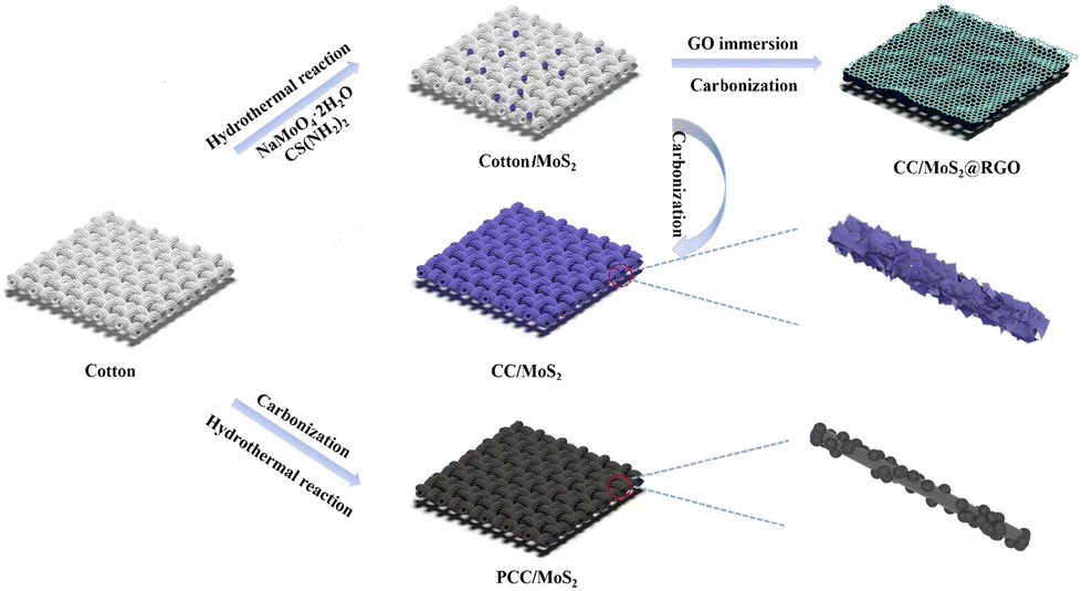 | ||
| Fig. 1 Schematic illustration of the fabrication of the PCC/MoS2, CC/MoS2 and CC/MoS2@RGO textiles. | ||
The morphologies and microstructures of the PCC/MoS2 textiles are observed by SEM. Cotton cloth is made up of braided bundles interlaced in a perpendicular direction (Fig. S1a and c†), and the diameter of a single fiber is approximately 20 μm. The cross-sectional view is realized by cutting the cotton textile (Fig. S1e†). As a flexible substrate, such hollow inside provides a large surface area for the growth of active materials, which plays a vital role in achieving high areal capacity. As expected, PCC inherits the original feature, but the size is shortened to 10 μm (Fig. S1b and d†). It can be seen in Fig. S1f† that holes are distributed on the surface, which may be ascribed to the release of gases during high-temperature calcination. Importantly, the textile is changed from insulating to conductive. For the PCC/MoS2-1 material, discrete MoS2 nanoflowers, which possess a size of 440–850 nm, are assembled by stacked nanosheets and distributed on the smooth PCC fibers (Fig. 2a). With the addition of precursors, the MoS2 nanoflowers are completely replaced by vertically arranged nanosheets, while the PCC fibers can hardly be recognized in the high-resolution SEM image (Fig. 2b). Due to the enormous MoS2 nanosheets, the PCC fibers of PCC/MoS2-2 textile break slightly. This phenomenon becomes more severe for PCC/MoS2-3. It is apparent that cracks are almost present on each PCC fiber, which inevitably separates the hierarchical MoS2 nanosheets (Fig. 2c). Moreover, extra spherical MoS2 nanoflowers can be found again on the external surface of the MoS2 nanosheets. Considering that the continuous conductive pathways and adequate MoS2 coverage are beneficial for electron transport and high capacity, other compositions, like PCC/MoS2-1.5 and CC/MoS2-1.5, were then selected for further study and comparison.
 | ||
| Fig. 2 SEM images of the (a1–a3) PCC/MoS2-1, (b1–b3) PCC/MoS2-2 and (c1–c3) PCC/MoS2-3 textiles. | ||
Fig. 3 displays the SEM images of the PCC/MoS2-1.5, CC/MoS2-1.5, and CC/MoS2@RGO-700 (700 represents the combustion temperature of 700 °C) textiles. For the former two samples, although the mass of Na2MoO4·2H2O and CS(NH2)2 are identical, it is obvious that the MoS2 content on CC/MoS2-1.5 is more than that on PCC/MoS2-1.5, which is demonstrated by the TG results (Fig. S2†). As for PCC/MoS2-1.5, gaps exist between the adjacent MoS2 nanoflowers (Fig. 3a). Nevertheless, the microfibers of the CC/MoS2-1.5 textile almost disappeared, and it is densely covered with MoS2 nanosheets (Fig. 3b). By measuring the diameters of the microfibers in CC/MoS2-1.5, it can be inferred that the widths are in the range of 7–17 μm, which are thicker than PCC, suggesting direct pyrolysis exerts a more striking impact on the cotton textile than the hydrothermal process. Specifically, the appearance of CC/MoS2-1.5 is similar to that of PCC/MoS2-2, which can be explained by the superior hydrophilicity of cotton cloth, leading to favorable ion adsorption. More excitingly, the CC/MoS2-1.5 textile is able to endure high temperature annealing, ensuring a robust structure without fracture. The low-magnification SEM images further confirm the structural integrity (Fig. S3†). Therefore, this optimized composition was adopted for further RGO decoration. As can be seen in Fig. S4a,† the microfibers become rough, indicating the successful encapsulation of RGO. The cross-section image presents one-dimensional tubular morphology, while the hollow interior is filled with CC/MoS2@RGO-700 as well (Fig. S4b and c†). This hollow architecture facilitates the diffusion of ions and accommodates the volume expansion/contraction during sodiation/desodiation. The white cotton textile changes to black after MoS2 modification, and maintains its black color with RGO encapsulation (Fig. S5†). On the other hand, the dimension of the Cotton/MoS2 fabric is approximately consistent with that of the pristine cotton, while the as-prepared CC/MoS2@RGO-700 material is decreased to 46 cm in length. The original flexible characteristics are inherited by the CC/MoS2@RGO-700 textile, which can be bent in any angle. Moreover, Fig. 3c demonstrates that Cotton/MoS2-1.5 is uniformly wrapped by a thin and wrinkled RGO film. Because the surface of Cotton/MoS2-1.5 is far from flat, bumps are formed on CC/MoS2@RGO-700. The integral and compact RGO not only ensures high conductivity, but also buffers the volume change of MoS2, which are both beneficial for enhancing the sodium storage performances. Transmission electron microscopy (TEM) indicates that each MoS2 sheet has a layer number of 10 or less, and it displays an interlayer distance of 0.68 nm, larger than the theoretical (002) spacing (Fig. S4d and e†). The AFM results further validate the multilayer MoS2 nanosheets property, evidenced by the average thickness of 1.5 nm (Fig. S6†). The selected area electron diffraction (SAED) pattern is shown in Fig. S4f,† and the diffraction rings exhibit (110) and (100) planes of polycrystalline MoS2. Energy dispersive X-ray spectroscopy (EDX) mapping on SEM manifests the homogeneous distribution of Mo, S, and C elements over the entire part of the microfibers (Fig. 3d).
 | ||
| Fig. 3 SEM images of (a1 and a2) PCC/MoS2-1.5, (b1 and b2) CC/MoS2-1.5, and (c1 and c2) CC/MoS2@RGO-700; (d) EDX mapping images of CC/MoS2@RGO-700. | ||
The crystalline planes of PCC/MoS2, CC/MoS2, and CC/MoS2@RGO-700 are analyzed by X-ray diffraction (XRD) (Fig. 4a and Fig. S7†). Broad diffraction peaks at 13.5°, 32.4°, and 58° are noticed among the PCC/MoS2 samples, which can be indexed to the (002), (100), and (110) planes of hexagonal MoS2 (JCPDS No. 37-1492), respectively. Although the characteristic peak of PCC is also detected at 23°, it decreases stepwise from PCC/MoS2-1 to PCC/MoS2-3, ascribed to the increasing amount of MoS2 in the textiles. Moreover, an additional sharp peak at 12.5° and a series of impurity peaks between 20° and 30° can be identified in PCC/MoS2-3, which can be theoretically assigned to disodium dimolybdate or Mo-based oxides, implying that the generation of MoS2 is sensitive to the Na2MoO4·2H2O and CS(NH2)2 concentrations. High phase purity is also demonstrated by CC/MoS2-700, CC/MoS2-800, and CC/MoS2-900. Nevertheless, for CC/MoS2@RGO-700, the distinct peak at 13.5° is replaced by the (002) and (004) planes at 9° and 18°, respectively, suggesting the formation of 1T-MoS2 with expanded interlayer spacing, in agreement with TEM observation.19,20 In the subsequent parts, the optimum compositions with the addition of 150 mg Na2MoO4·2H2O are selected for further investigation, and they are designated as PCC/MoS2, CC/MoS2, and CC/MoS2@RGO-X (X represents the combustion temperature) for short.
 | ||
| Fig. 4 (a) XRD patterns of CC/MoS2 and CC/MoS2@RGO-700 textiles; (b) Raman spectrum of the CC/MoS2@RGO-700 textile; (c) TG curves of the CC/MoS2@RGO-700 textile; (d) comparison of the conductivities among PCC/MoS2-900, CC/MoS2-900 and CC/MoS2@RGO-700; high-resolution XPS spectra of (e) Mo 3d, (f) S 2p and (g) C 1s; (h) electrolyte contact angle of CC/MoS2-900 and CC/MoS2@RGO-700. | ||
As presented in Fig. 4b, the structure of CC/MoS2@RGO-700 is revealed by the Raman spectrum. The four peaks at 144.7 (J1), 228.5 (J2), 282.3 (E1g), and 337.2 (J3) cm−1 further confirm the presence of 1T-MoS2.21 The additional two peaks at 378.6 and 400.3 cm−1 are ascribed to the E12g vibrational mode of the Mo–S plane and the A1g out-of-plane vibrational mode of hexagonal MoS2, indicating the coexistence of the 1T and 2H phases of MoS2.22,23 In addition, the broad D and G bands with an intensity ratio of 1.07 are found at 1350 and 1585 cm−1, respectively, which are derived from the CC textile and RGO.24–27
TG analysis was conducted on PCC/MoS2, CC/MoS2 and CC/MoS2@RGO composites from room temperature to 700 °C in an oxygen atmosphere to determine the content of the MoS2 active material (Fig. S2† and Fig. 4c). For the cotton textile, weight loss is inevitable during the hydrothermal reaction and pyrolysis. Because of the above reason, the as-prepared samples are firstly cut into discs with a diameter of 10 mm. The disc possessing an average mass loading is selected for TG tests. According to the TGA results of PCC/MoS2, CC/MoS2 and CC/MoS2@RGO, the mass fraction of MoS2 is calculated to be 21.5%, 28.7%, and 28.7%, respectively.
Electrical conductivity is also an important factor for flexible electrodes. As demonstrated in Fig. 4d, PCC/MoS2-900 and CC/MoS2-900 exhibit remarkable conductivity values of 1.36 and 2.00 S cm−1, respectively. According to the data, it is speculated that the MoS2 nanostructures are bonded more tightly with each other and the textile on CC/MoS2-900 than PCC/MoS2-900, leading to the high conductive pathways. Particularly, the conductivities are substantially superior to that of CC/MoS2@RGO-700 (0.42 S cm−1) due to the beneficial effect of high temperature annealing. With regard to CC/MoS2-700, the conductivity is as low as 0.18 S cm−1 (Fig. S8†), which indicates that RGO wrapping can guarantee lightweight and flexible microfibers with ideal conductivity. Apart from that, MoS2-based anode materials suffer from unavoidable volume expansion, resulting in cycling instability. The significance of RGO encapsulation is that it also serves as a buffer for accommodating the volume variation and ensures structure robustness.
The chemical valence states of the CC/MoS2@RGO-700 flexible electrode are evaluated by X-ray photoelectron spectra (XPS). In the high-resolution Mo 3d spectrum, the two peaks located at 233 and 229.8 eV are ascribed to Mo 3d3/2 and 3d5/2 of Mo4+, respectively, which are accompanied by tiny satellite peaks.28–30 As shown in Fig. 4e, both sides are also fitted by peaks at 236.2 and 227.1 eV due to the existence of Mo6+ and S 2s, suggesting the Mo–S bond in MoS2.31,32 The S 2p is deconvoluted into main peaks at 162.6 and 163.9 eV (Fig. 4f), which is assigned to 2p3/2 and 2p1/2, respectively.33,34 The C 1s of Fig. 4g reveals a strong C–C peak at 284.8 eV and a broad peak of C–OH/C–O–Mo at 286.2 eV.35
The hydrophilic properties of CC/MoS2-900 and CC/MoS2@RGO-700 are compared via recording the motion of an electrolyte droplet, as illustrated in Fig. 4h. When an electrolyte droplet is in contact with the CC/MoS2-900 surface, it spreads after 3.3 s. In contrast, the electrolyte droplet is adsorbed by CC/MoS2@RGO-700 quickly and the contact angle (CA) reaches 0° within 1.6 s, demonstrating the facile electrolyte immersion.
The textile-based materials are used as flexible and self-standing electrodes, which are assembled into SIBs and LIBs without the addition of a binder and conductive agents. As for SIBs, the cyclic voltammetry of the CC/MoS2@RGO-700 electrode is tested at 0.1 mV s−1 in the potential range of 0.1–3 V and is shown in Fig. 5a. During the first cathodic sweep, a broad reduction peak at 0.44 V and a distinct peak at 0.1 V can be detected, which is assigned to the insertion of Na+ into MoS2 with the formation of a solid-electrolyte interface (SEI) film and further transfer into Mo and Na2S, respectively. In the subsequent anodic scan, MoS2 is reconstructed, corresponding to the oxidation peak at 1.72 V, which agrees well with the literature.36–38 From the second cycle, the redox peaks are almost overlapped, manifesting the high reversibility and stable sodiation/desodiation process of the CC/MoS2@RGO-700 electrode. The reaction can be summarized as follows:
| MoS2 + xNa+ + xe− → NaxMoS2 (x < 1) | (1) |
| NaxMoS2 + (4 − x)Na+ + (4 − x)e− → Mo + 2Na2S | (2) |
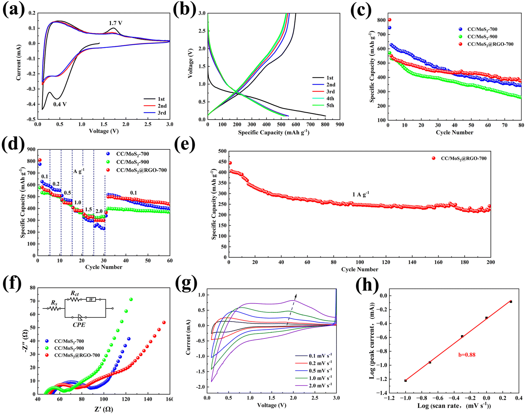 | ||
| Fig. 5 Sodium storage performances of the textile-based flexible electrodes: (a) CV curves of the CC/MoS2@RGO-700 electrode; (b) discharge/charge profiles of the CC/MoS2@RGO-700 electrode for the first five cycles at 100 mA g−1; (c) cycling performances of the CC/MoS2-700, CC/MoS2-900, and CC/MoS2@RGO-700 electrodes at 0.1 A g−1; (d) rate capabilities of the CC/MoS2-700, CC/MoS2-900 and CC/MoS2@RGO-700 electrodes; (e) long-term cycling stability of CC/MoS2@RGO-700 at 1.0 A g−1; (f) Nyquist plots of the CC/MoS2-700, CC/MoS2-900 and CC/MoS2@RGO-700 electrodes after 5 cycles, and the equivalent circuit is shown in the inset; (g) CV curves of the CC/MoS2@RGO-700 electrode with scan rates from 0.1 to 2 mV s−1; (h) plots of log(scan rate) versus log(peak current). | ||
Fig. 5b displays the galvanostatic discharge/charge profiles of CC/MoS2@RGO-700 electrode at the current density of 100 mA g−1. The initial discharge and charge capacities are 802.6 and 599.4 mA h g−1, respectively, corresponding to a coulombic efficiency of 74.7%. There are two sloping regions in the discharge curve, consistent with the CV results. The long sloping region originates from 0.92 to 0.32 V, while the low-voltage segment appears at a voltage below 0.32 V. The discharge capacities steadily drop to ∼520 mA h g−1 and the coulombic efficiency is evaluated to 97% in the following cycles.
Fig. 5c and Fig. S9† present the specific capacity versus cycle number of CC/MoS2 and CC/MoS2@RGO electrodes at 100 mA g−1. The influences of temperatures between 600 °C and 900 °C are also evaluated. The initial discharge capacities of CC/MoS2-700, CC/MoS2-800, CC/MoS2-900, CC/MoS2@RGO-600, CC/MoS2@RGO-700, CC/MoS2@RGO-800 and CC/MoS2@RGO-900 are 747.5, 667.3, 571.4, 796.6, 802.6, 513.2 and 530.2 mA h g−1, respectively. As expected, the CC/MoS2@RGO-700 electrode maintains its superiority and delivers the highest capacity of 374.4 mA h g−1 after 80 cycles. Apparently, associated with the CC/MoS2-700 and CC/MoS2-900 electrodes, the capacities quickly degrade to 344.8 and 260.8 mA h g−1 after cycling. Moreover, the performance of the CC/MoS2@RGO-600 (319.8 mA h g−1) electrode stands out among CC/MoS2-800, CC/MoS2@RGO-800, and CC/MoS2@RGO-900, but it is inferior to that of CC/MoS2@RGO-700. For comparison, the sodiation behavior of PCC/MoS2-900 is accessed (Fig. S10†). It exhibits an initial discharge capacity of 700.7 mA h g−1 with a low coulombic efficiency of 73.9%. Subsequently, the rapid capacity decay continues, and only 471.8 and 152 mA h g−1 are obtained at the 2nd and 80th cycles, respectively, corresponding to a capacity retention of 32%. Furthermore, the CC/MoS2@RGO-700 textile is evaluated at a low current density of 50 mA g−1 (Fig. S11†). It provides discharge/charge capacities of 862/648.1 mA h g−1, retaining 43.2% after 50 cycles.
Based on the above results, Fig. 5d plots the rate capacities of CC/MoS2-700, CC/MoS2-900, and CC/MoS2@RGO-700 electrodes. Reversible capacities of 560.3, 510.9, 447.3, 382.8, 322.2 and 300.6 mA h g−1 are achieved by CC/MoS2@RGO-700 at the current densities of 100, 200, 500, 1000, 1500 and 2000 mA g−1, respectively, exceeding the CC/MoS2-700 electrode at high rates. When the current density is set back to 100 mA g−1, the specific capacity of CC/MoS2@RGO-700 quickly recovers to 482.5 mA h g−1. Notably, the selected well-defined discharge/charge voltage profiles with small polarization at various current rates further verify the reversible electrochemical reaction (Fig. S12†). For the CC/MoS2-900 electrode, the capacity at 2 A g−1 even exceeds that of CC/MoS2@RGO-700, originating from the favorable conductive properties. However, when the current is switched into 100 mA g−1, a discharge capacity of 400.1 mA h g−1, only 82.9 percent of CC/MoS2@RGO-700, is retained. Moreover, the CC/MoS2@RGO-700 electrode demonstrates better rate capabilities in comparison with other reported MoS2-based materials, as presented in Fig. S13.† Such remarkable rate performances of the CC/MoS2@RGO-700 textile can be attributed to the combination of the alleviated volume expansion and facilitated electron transfer, endowed by RGO modification. The rate performances of the PCC textiles synthesized at different temperatures are provided to clarify that the capacities indeed come from them (Fig. S14†). Overall, the PCC-700 electrode reveals the best rate capability among them. When it is tested in sodium half cells, the PCC-700 electrode shows reversible capacities of 91.1, 70.5, 44.2, 20.3, 9.6, and 8.3 mA h g−1 at the current densities of 100, 200, 500, 1000, 1500 and 2000 mA g−1, respectively, which are negligible to the whole capacity.
The long-term cycling stability of the CC/MoS2@RGO-700 electrode is carried out at a high current density of 1000 mA g−1 (Fig. 5e). CC/MoS2@RGO-700 exhibits a sharp capacity decay at the beginning of 40 cycles, and then a relatively slight fade. The capacity decline may be attributed to the microstructure evolution of the CC/MoS2@RGO-700 electrode, especially the textile matrix, including fiber rearrangements, deformation, cross-linking points change and even fracture. Finally, it offers 225.3 mA h g−1 after 200 cycles, corresponding to 50.7% of the initial capacity.
Fig. 5f shows the electrochemical impedance spectroscopy (EIS) tests, which are conducted to access the charge transfer of the CC/MoS2-700, CC/MoS2-900, and CC/MoS2@RGO-700 electrodes after 5 and 10 cycles. Acquired from the equivalent circuit, the charge transfer resistance (Rct) of CC/MoS2-900 is 25.6 Ω, which is much lower than those of CC/MoS2@RGO-700 (30.2 Ω) and CC/MoS2-700 (37.7 Ω). This further confirms the experimental results of conductivity, as mentioned above. Nevertheless, CC/MoS2@RGO-700 displays the minimum Rct of 36.5 Ω during subsequent cycling (Fig. S15†), which may benefit from the stable SEI film and RGO encapsulation, accommodating structure expansion/contraction and pulverization.39 Thus, rapid electron transportation in the whole Na+ insertion/extraction process can be ensured. The concrete data are shown in Table S1.†
Moreover, the Na+ diffusion coefficient (DNa) of the CC/MoS2@RGO-700 textile is determined by the galvanostatic intermittent titration technique (GITT), which can be expressed by Fick's second law.
 | (3) |
As described in eqn (3), τ stands for current pulse time, m, Vm, and M are the mass, molar volume and molar weight of the anode material, respectively, A represents the electrode surface area, ΔEs is the steady-state voltage change, and ΔEτ is the voltage change during the interval of a current pulse subtracting the IR drop.40,41 The GITT curve and DNa of CC/MoS2@RGO-700 are shown in Fig. S16,† and DNa is calculated to be in the range between 2.01 × 10⁻¹³ and 2.84 × 10⁻¹¹ cm2 s−1.
The electrokinetic analysis of CC/MoS2@RGO-700 is evaluated at scan rates ranging from 0.1 to 2 mV s−1 (Fig. 5g). It is obvious that the cathodic and anodic peaks are enhanced slightly as the scan rates go up. The current i and scan rates v can be linked through eqn (4) and (5):42,43
| i = avb | (4) |
| logi = loga + blogv | (5) |
The b values, which are equal to the slope, can be extracted from the relationship of logi vs. logv curves. It is also a significant parameter in determining whether the redox reaction is mainly controlled by a diffusion process or not. Particularly, the value of b = 0.5 indicates the limitation of sodium diffusion, whereas b = 1 demonstrates the surface capacitive behavior. As can be seen in Fig. 5h, the marked anodic peak is fitted to be 0.88, suggesting the dominant pseudocapacitive response.
In addition, the ratio at a specific scan rate can be quantified based on eqn (6).44
| i = k1v + k2v0.5 | (6) |
where k1v and k2v0.5 are derived from the capacitive and diffusion contributions, respectively. The respective contributions of CC/MoS2@RGO-700 are calculated in Fig. S17,† and the maximum capacitive proportion reaches 46% at the scan rate of 2 mV s−1.
Ex situ XRD is employed to elucidate the sodiation/desodiation mechanism in the initial discharge/charge cycle. As revealed in Fig. S18,† when the CC/MoS2@RGO-700 electrode is discharged to 0.1 V, signals located at 39° and 40° may be ascribed to the (220) and (110) planes of Na2S (#23-0441) and Mo (#42-1120), respectively, matching well with the conversion reaction. In addition, during the desodiation reaction from 0.1 to 3.0 V, peaks at 32.4° and 57° correspond to tje (100) and (110) planes of MoS2 (#37-1492), respectively, proving the reversible structure evolution.37 Two strong and broad peaks at 24° and 43° can be observed in the discharge/charge curves, belonging to the characteristic (002) and (100) planes of pyrolyzed cotton textile substrate, respectively. Collectively, the tight internal bonding, moderate electrical conductivity, dominant pseudocapacitive behavior, fast Na-diffusion kinetics, stable charge transfer resistance, and strain-relieved feature endow the CC/MoS2@RGO-700 electrode with outstanding electrochemical performances. It is noted that the binder-free configuration and the optimized PCC-700 matrix offer contributions to the high capacity.
As an optimal material, the CC/MoS2@RGO-700 electrode is focused on and found to exhibit outstanding lithium storage performances. Fig. 6a shows the CV curves of the CC/MoS2@RGO-700 electrode for the first three cycles in the voltage range of 0.1–3 V. In the first cycle, the cathodic peaks consisted of an inconspicuous peak starting from 1.12 V and a dominant peak at 0.5 V, which can be explained by the intercalation of lithium ions into CC/MoS2@RGO-700 and the subsequent reduction of LixMoS2 into Li2S and Mo induced by the conversion mechanism.45,46 Meanwhile, the anodic peak at 2.2 V represents the reverse delithiation reaction with reconstruction of CC/MoS2@RGO-700.47 However, during the second cycle, cathodic peaks appearing at 1.8 V and 0.9 V are due to the formation of Li2S and LixMoS2, respectively.48 Moreover, this change of the redox peaks relates to the SEI originating from the first cycle. After that, the cathodic and anodic peaks are analogous, indicating the reversible process in the following cycles.
 | ||
| Fig. 6 Electrochemical performances of the CC/MoS2@RGO-700 electrode for LIBs: (a) CV curves of the CC/MoS2@RGO-700 electrode at 0.1 mV s−1; (b) discharge/charge profiles for the initial five cycles at 100 mA g−1; (c) cycling performance and the corresponding coulombic efficiency of CC/MoS2@RGO-700 at 0.1 A g−1; (d) rate capability of the CC/MoS2@RGO-700 electrode; (e) long-term cycling stability of CC/MoS2@RGO-700 at 1.0 A g−1 and 2.0 A g−1; (f) CV curves of the CC/MoS2@RGO-700 electrode at various scan rates; (g) plots of log(scan rate) versus log(peak current); (h) capacitive contribution of the CC/MoS2@RGO-700 electrode at the scan rate of 2 mV s−1; (i) normalized ratio of the capacitive or diffusion-controlled process for the CC/MoS2@RGO-700 electrode at different scan rates. | ||
Fig. 6b presents the galvanostatic discharge/charge curves of CC/MoS2@RGO-700 at 0.1 A g−1. The 1st discharge profile includes a plateau at 1.0–0.56 V and a sloping region of 0.56–0.1 V, consistent with the CV results. On the other hand, it delivers an extraordinary discharge capacity of 1730.3 mA h g−1 with an initial coulombic efficiency of ∼49.5%, presumably due to the SEI film, electrolyte decomposition, and the advantages of capacity generation associated with the cotton-derived current collector, as evidenced from Fig. S19 and Table S2.†49 This phenomenon is also verified by the electrochemical test at 0.05 A g−1 (Fig. S20†). The CC/MoS2@RGO-700 electrode exhibits 1933.7 mA h g−1 for the initial cycle, and the slow capacity decline continues over the succeeding 30 cycles, indicating good structural integrity. Simultaneously, as shown in Fig. 6c, the CC/MoS2@RGO-700 electrode demonstrates stable lithiation/delithiation processes for at least 300 cycles, and holds a reversible capacity of 482 mA h g−1. More interestingly, the CC/MoS2@RGO-700 electrode demonstrates superior rate performances as well (Fig. 6d). Specific capacities of 770.1, 639, 509.4, 403.9, 331.6, 269.9 mA h g−1 can be obtained at the current densities of 0.1, 0.2, 0.5, 1, 1.5 and 2 A g−1, respectively. When the current density turns back to 0.1 A g−1 for another 5 cycles, the capacity quickly recovers to 609.7 mA h g−1. Similarly, the high-rate cycling continues, and the capacity is as high as 496.7 mA h g−1 after 350 cycles, accompanied with CE of 99%.
Long-term cycling performances are carried out on the CC/MoS2@RGO-700 electrode in Fig. 6e at 1 A g−1 and 2 A g−1 after undergoing five cycles at 0.1 A g−1. It is apparent that the rapid capacity fading can be observed at 1 A g−1 over the first 300 cycles. In contrast, the CC/MoS2@RGO-700 electrode at 2 A g−1 suffers from a gradual decrease, but displays slightly lower capacity. At the end of 1000 cycles, the CC/MoS2@RGO-700 electrode yields a capacity of 205.3 mA h g−1 at 1 A g−1, exhibiting a fluctuation of only 0.042% per cycle over the further 700 cycles. More significantly, the electrode can still retain its stable reversible capacity of 141.7 mA h g−1 at 2.0 A g−1 after 2000 cycles. To verify the cycling stability of the CC/MoS2@RGO electrode, SEM and XRD are employed to characterize the morphology and structure of the CC/MoS2@RGO-700 electrode after cycling (Fig. S21 and S22†). It can be clearly observed that the MoS2 nanosheets are encapsulated by the thin RGO film, proving that the CC/MoS2@RGO-700 electrode can preserve the structural stability during the repeated lithiation/delithiation process. In the charging stage of 3 V, (103) and (110) peaks at 38.5° and 60.7° appear, respectively, indicating the reconstruction of MoS2.
Then, CVs at different scan rates are employed to assess the electrochemical behavior. As illustrated in Fig. 6f, each CV curve is almost the same. Consequently, the reduction peak 1 and oxidation peak 2 are chosen for analysis. Acquired from the log(peak current, i)–log(scan rate, v) plot and eqn (6), the b values of peaks 1 and 2 are estimated to be 0.79 and 0.82 (Fig. 6g), respectively, reflecting a combination of both diffusion-controlled and pseudocapacitive processes. On the basis of eqn (6), the CC/MoS2@RGO-700 electrode holds pseudocapacitive contributions of 40.6%, 44.5%, 51.5%, 60.4%, and 76.4% at scan rates of 0.1, 0.2, 0.5, 1.0, and 2 mV s−1, respectively, as exhibited in Fig. 6i. The separation of the pseudocapacitive contribution to the total electric current of the CV data at 2 mV s−1 is displayed in Fig. 6h. The favorable capacitive contribution at high scan rates enables remarkable electrochemical kinetics.
EIS measurements of the CC/MoS2@RGO-700 electrode after 5, 50, and 100 cycles at a fully charged state are depicted in Fig. S23.† The Nyquist plots display a semicircle in high frequencies, a semicircle in middle frequencies, and a straight line in the low-frequency region, which are attributed to the SEI film resistance (Rs), Rct and the Li+ diffusion impedance.50–52 The profiles are similar, suggesting the lithium storage mechanism is maintained in the entire cycling. The equivalent circuit model used for fitting is shown in the inset. The Rct value is calculated to be 42.8 Ω after 5 cycles, and slightly increased to 50.2 Ω and 68.8 Ω after 50 and 100 cycles, respectively, in agreement with the satisfactory cycling stability.
To confirm the practical application of the CC/MoS2@RGO-700 textile electrode, full cells are assembled via adopting commercial LiFePO4 as the cathode, and the configuration is presented in Fig. 7a. The morphology, structure, and electrochemical performances of LiFePO4 are shown in Fig. S24–S27.† The CC/MoS2@RGO-700||LiFePO4 full cell is tested at the current density of 100 mA g−1 in the voltage window of 1.0–3.7 V (Fig. 7b). It delivers an initial discharge/charge capacity of 849.6/236.9 mA h g−1 with a low CE of 27.9%, which may be induced by the SEI film and irreversible intercalation of Li+.53 The capacity is enhanced quickly to 335.1 mA h g−1 at the 35th cycle, and then it tends to be stable and 358.7 mA h g−1 is reserved with CE around 91.7% after 80 cycles. The noticeable improved capacity can be due to the activation process of the cathode and anode materials.54 In addition, the performances can be boosted by modifying the properties of the cathode, verifying the potential application of this system.
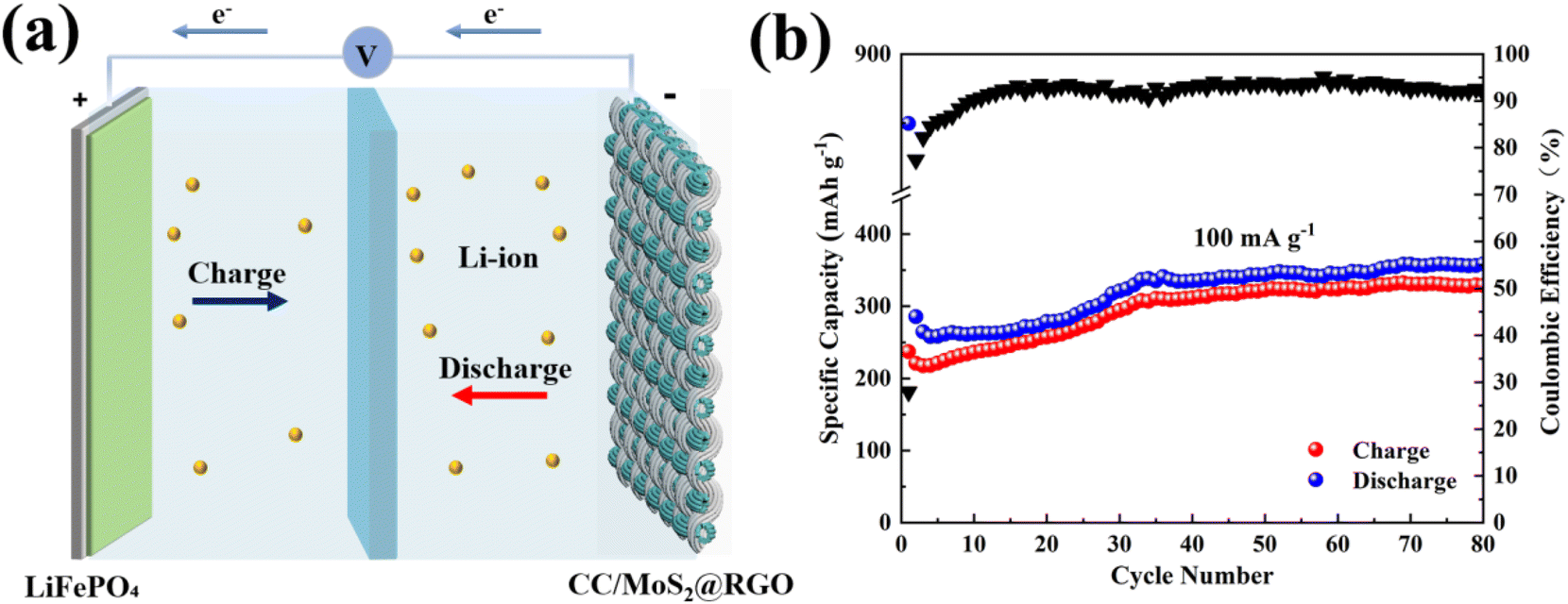 | ||
| Fig. 7 (a) Schematic illustration of the CC/MoS2@RGO-700||LiFePO4 full cell; (b) cycling performance of the full cell at 100 mA g−1. | ||
Owing to the surprising different energy storage behaviors, SEM was performed to reveal the morphology evolutions of the CC/MoS2@RGO-700 textile in the Li and Na half cells. In terms of SIBs, the CC/MoS2@RGO-700 fibers still maintain the structural integrity and are encapsulated by thin RGO film upon cycling, confirming the beneficial effect of alleviating the volume expansion (Fig. 8a). From the edge of the fiber, it can be observed that the MoS2 nanosheets are replaced by 240–650 nm nanograins on the wrinkled surface (Fig. 8b). In contrast, the appearance of MoS2 nanoflowers assembled by nanosheets from disclosed fibers in LIBs upon extended cycling (Fig. 8c) reveals that the sodium insertion/extraction reactions possess a striking nanomachine effect on grinding the MoS2 nanosheets into nanoparticles, owing to the larger radius of the Na+ ion (1.02 Å) compared to that of the Li ion (0.76 Å).55 Therefore, the ultrasmall particle sizes of the MoS2 nanograins ensure the high-rate capability for SIBs, while the moderate morphology evolution guarantees a reversible lithiation/delithiation process in the long-term cycling.
 | ||
| Fig. 8 SEM images of the CC/MoS2@RGO-700 electrode in (a and b) Na and (c) Li half cells after cycling. | ||
4. Conclusion
In summary, we confirmed the cotton textile as a flexible current collector without metal deposition and carbon coating. PCC/MoS2 and CC/MoS2 are developed, but CC/MoS2 favors high loading and continuous conductive pathways for the active material. Therefore, by immersing and drying in GO solution, the CC/MoS2@RGO textile, which holds many advantages, including high flexibility, good electronic conductivity, ease of electrolyte immersion, and superior electrochemical performances, is subsequently fabricated. As SIBs anodes, reversible capacities of 560.3, 510.9, 447.3, 382.8, 322.2 and 300.6 mA h g−1 were obtained by the CC/MoS2@RGO-700 flexible electrodes at the current densities of 100, 200, 500, 1000, 1500 and 2000 mA g−1, respectively, manifesting the satisfactory rate capability. Meanwhile, CC/MoS2@RGO-700 displays 141.7 mA h g−1 at 2 A g−1 after 2000 cycles for LIBs with small fluctuation. Kinetic analysis indicates the pseudocapacitive contribution of 76.4% at a scan rate of 2 mV s−1. Moreover, as a proof-of-concept, full batteries are assembled, delivering an initial discharge capacity of 849.6 mA h g−1. It is revealed that sodiation/desodiation possesses a more striking nanomachine effect on grinding the MoS2 nanoflowers into nanoparticles, resulting in the different metal storage behaviors. This proposed strategy paves the way for cotton textile-based flexible electrodes, which simplifies the process, and is of great significance for carbon neutralization.Author contributions
Xue Liu: conceptualization, validation, writing – original draft, supervision. Haicong Ji: methodology, resources, data curation, investigation. Bin Peng: investigation, resources, data curation. Zhaoning Cui: investigation, data curation. Qiongzhen Liu: discussion, writing – review & editing. Qinghua Zhao: discussion, writing – review & editing. Liyan Yang: discussion, writing – review & editing. Dong Wang: supervision, discussion, writing – review & editing, project administration, funding acquisition.Conflicts of interest
The authors declare no conflict of interests.Acknowledgements
This work was supported by the National Natural Science Foundation of China (52102295 and U20A20257) and Application Foundation Frontier Project of Wuhan Science and Technology Bureau (2020010601012194). The authors thank “Wuhan Engineering Technology Research Center for Advanced Fibers” for providing partial support for materials processing.References
- J. Lee, B.-L. Zambrano, J. Woo, K. Yoon and T. Lee, Recent advances in 1D stretchable electrodes and devices for textile and wearable electronics: materials, fabrications, and applications, Adv. Mater., 2020, 32, 1902532 CrossRef CAS PubMed.
- H. Sun, Y. Zhang, J. Zhang, X.-M. Sun and H.-S. Peng, Energy harvesting and storage in 1D devices, Nat. Rev. Mater., 2017, 4, 1–12 Search PubMed.
- Y. Zhou, C.-H. Wang, W. Lu and L. Dai, Recent advances in fiber-shaped supercapacitors and lithium-ion batteries, Adv. Mater., 2020, 32, 1902779 CrossRef CAS PubMed.
- J. Xu, S.-K. Zhang, Z.-N. Wei, W.-R. Yan, X.-J. Wei and K.-J. Huang, Orientated VSe2 nanoparticles anchored on N-doped hollow carbon sphere for high-stable aqueous energy application, J. Colloid Interface Sci., 2021, 585, 12–19 CrossRef CAS PubMed.
- J.-Y. Xu, Y.-F. Xu, C.-L. Lai, T.-T. Xia, B.-N. Zhang and X.-S. Zhou, Challenges and perspectives of covalent organic frameworks for advanced alkali-metal ion batteries, Sci. China: Chem., 2021, 64, 1267–1282 CrossRef CAS.
- Y. Chen, H.-Y. Dong, Y.-Y. Li and J.-P. Liu, Recent advances in 3D array anode materials for sodium-ion batteries, Acta Phys. -Chim. Sin., 2021, 37, 2007075 Search PubMed.
- Y.-F. Zhu, Y. Xiao, S.-X. Dou, Y.-M. Kang and S.-L. Chou, Spinel/post-spinel engineering on layered oxide cathodes for sodium-ion batteries, eScience, 2021, 1, 13–27 CrossRef.
- M. Yao, H. Wang, R. Qian, T. Yao, J. Shi and Y. Cheng, Robust hollow TiO2 spheres for lithium/sodium ion batteries with excellent cycling stability and rate capability, Inorg. Chem. Front., 2021, 8, 5024–5033 RSC.
- T.-Y. Wang, S.-Q. Chen, H. Pang, H.-G. Xue and Y. Yu, MoS2-based nanocomposites for electrochemical energy storage, Adv. Sci., 2017, 4, 1600289 CrossRef.
- J. Xu, Q. Liu, Z. Dong, L.-N. Wang, X.-C. Xie, Y. Jiang, Z.-N. Wei, Y.-P. Gao, Y. Zhang and K.-J. Huang, Interconnected MoS2 on 2D graphdiyne for reversible sodium storage, ACS Appl. Mater. Interfaces, 2021, 13, 54974–54980 CrossRef CAS PubMed.
- X.-S. Zhou, L.-J. Wan and Y.-G. Guo, Binding SnO2 nanocrystals in nitrogen-doped graphene sheets as anode materials for lithium-ion batteries, Adv. Mater., 2013, 25, 2152–2157 CrossRef CAS PubMed.
- X.-J. He, R.-C. Wang, H.-M. Yin, Y.-F. Zhang, W.-K. Chen and S.-P. Huang, 1T-MoS2 monolayer as a promising anode material for (Li/Na/Mg)-ion batteries, Appl. Surf. Sci., 2022, 584, 152537 CrossRef CAS.
- J.-Q. He, C.-H. Lu, H.-B. Jiang, F. Han, X. Shi, J.-X. Wu, L.-Y. Wang, T.-Q. Chen, J.-J. Wang, Y. Zhang, H. Yang, G.-Q. Zhang, X.-M. Sun, B.-J. Wang, P.-N. Chen, Y.-G. Wang, Y.-Y. Xia and H.-S. Peng, Scalable production of high-performing woven lithium-ion fibre batteries, Nature, 2021, 597, 57–63 CrossRef CAS.
- C.-J. Zhang, J.-X. Zhu, H.-J. Lin and W. Huang, Flexible fiber and fabric batteries, Adv. Mater. Technol., 2018, 3, 1700302 CrossRef.
- Q. Chen, S. Sun, T. Zhai, M. Yang, X.-Y. Zhao and H. Xia, Yolk-shell NiS2 nanoparticle-embedded carbon fibers for flexible fiber-shaped sodium battery, Adv. Energy Mater., 2018, 8, 1800054 CrossRef.
- Y.-H. Zhu, S. Yuan, D. Bao, Y.-B. Yin, H.-X. Zhong, X.-B. Zhang, J.-M. Yan and Q. Jiang, Decorating waste cloth via industrial wastewater for tube-type flexible and wearable sodium-ion batteries, Adv. Mater., 2017, 29, 1603719 CrossRef PubMed.
- C. Hwang, W.-J. Song, J.-G. Han, S. Bae, G. Song, N.-S. Choi, S. Park and H.-K. Song, Foldable electrode architectures based on silver-nanowire-wound or carbon-nanotube-webbed micrometer-scale fibers of polyethylene terephthalate mats for flexible lithium-ion batteries, Adv. Mater., 2018, 30, 1705445 CrossRef PubMed.
- Y.-J. Zhu, M. Yang, Q.-Y. Huang, D.-R. Wang, R.-B. Yu, J.-Y. Wang, Z.-J. Zheng and D. Wang, V2O5 textile cathodes with high capacity and stability for flexible lithium–ion batteries, Adv. Mater., 2020, 32, 1906205 CrossRef CAS.
- H.-L. Fan, P.-C. Mao, G.-X. Lan, C. Liu, J.-Y. Chen, Z.-Y. Wang, Z.-P. Li, R.-G. Zheng, Y.-G. Liu and H.-Y. Sun, Ultrathin metallic-phase molybdenum disulfide nanosheets stabilized on functionalized carbon nanotubes via covalent interface interaction for sodium- and lithium-ion storage, ACS Appl. Energy Mater., 2021, 4, 9440–9449 CrossRef CAS.
- Z.-Q. Wei, P.-C. Mao, C. Liu, G.-X. Lan, M. Ahmad, R.-G. Zheng, Z.-Y. Wang, H.-Y. Sun and Y.-G. Liu, Covalent pinning of highly dispersed ultrathin metallic-phase molybdenum disulfide nanosheets on the inner surface of mesoporous carbon spheres for durable and rapid sodium storage, ACS Appl. Mater. Interfaces, 2021, 13, 58652–58664 CrossRef CAS PubMed.
- L.-N. Wang, X.-C. Tan, Q.-G. Zhu, Z. Dong, X. Wu, K.-J. Huang and J. Xu, The universality applications of MoS2@MnS heterojunction hollow microspheres for univalence organic or multivalence aqueous electrolyte energy storage device, J. Power Sources, 2022, 518, 230747 CrossRef CAS.
- Y. Wang, W. Kang, D. Cao, X. Fan, H. Yang, Z. Yang and D. Sun, Yolk-shell ZnS@NC@MoS2 nanoboxes with enhanced sodium storage capability, Appl. Surf. Sci., 2022, 574, 151715 CrossRef CAS.
- L.-B. Tang, B. Zhang, T. Peng, Z.-J. He, C. Yan, J. Mao, K. Dai, X.-W. Wu and J.-C. Zheng, MoS2/SnS@C hollow hierarchical nanotubes as superior performance anode for sodium-ion batteries, Nano Energy, 2021, 90, 106568 CrossRef CAS.
- Y. Zhang, W. Zhong, P. Tan, Y. Niu, X. Zhang and M. Xu, Heterogeneous interface design of bimetallic selenide nanoboxes enables stable sodium storage, Inorg. Chem. Front., 2021, 8, 4796–4805 RSC.
- J. Xu, Y.-B. Liu, P.-L. Chen, A. Wang, K.-J. Huang, L.-X. Fang and X. Wu, Interlayer-expanded VS2 nanosheet: fast ion transport, dynamic mechanism and application in Zn2+ and Mg2+/Li+ hybrid batteries systems, J. Colloid Interface Sci., 2022, 620, 119–126 CrossRef CAS.
- J. Xu, Z. Dong, K.-J. Huang, L.-N. Wang, Z.-N. Wei, L. Yu and X. Wu, Flexible design of large layer spacing V-MoS2@C cathode for high-energy zinc-ion battery storage, Scr. Mater., 2022, 209, 114368 CrossRef CAS.
- E.-L. Gu, J.-Y. Xu, Y.-C. Du, X.-F. Ge, X.-S. Zhu, J.-C. Bao and X.-S. Zhou, Understanding the influence of different carbon matrix on the electrochemical performance of Na3V2(PO4)3 cathode for sodium-ion batteries, J. Alloys Compd., 2019, 788, 240–247 CrossRef CAS.
- F.-Z. Chen, D. Shi, M.-Z. Yang, H.-H. Jiang, Y.-L. Shao, S.-Z. Wang, B.-G. Zhang, J.-X. Shen, Y.-Z. Wu and X.-P. Hao, Novel designed MnS-MoS2 heterostructure for fast and stable Li/Na storage: insights into the advanced mechanism attributed to phase engineering, Adv. Funct. Mater., 2021, 31, 2007132 CrossRef CAS.
- X.-D. Zhang, K.-L. Liu, S.-J. Zhang, F.-J. Miao, W.-D. Xiao, Y.-L. Shen, P. Zhang, Z. Wang and G.-S. Shao, Enabling remarkable cycling performance of high-loading MoS2@Graphene anode for sodium ion batteries with tunable cut-off voltage, J. Power Sources, 2020, 458, 228040 CrossRef CAS.
- Z.-Y. Zhang, S.-L. Wu, J.-Y. Cheng and W.-J. Zhang, MoS2 nanobelts with (002) plane edges-enriched flat surfaces for high-rate sodium and lithium storage, Energy Storage Mater., 2018, 15, 65–74 CrossRef.
- X. Liu, H. Xu, H.-C. Ji, K. Zhang and D. Wang, Featuring surface sodium storage properties of confined MoS2/bacterial cellulose-derived carbon nanofibers anode, Appl. Surf. Sci., 2020, 530, 147261 CrossRef CAS.
- J. Zang, L. Yu, B. Zheng, N. Li, J. Xi, X. Qiu, Q. Shi and H.-H. Zheng, Carbon microtube textile with MoS2 nanosheets grown on both outer and inner walls as multifunctional interlayer for lithium-sulfur batteries, Adv. Sci., 2020, 7, 1903260 CrossRef PubMed.
- P.-Q. Guo, K. Sun, D.-Q. Liu, P. Cheng, M.-Z. Lv, Q.-M. Liu and D.-Y. He, Molybdenum disulfide nanosheets embedded in hollow nitrogen-doped carbon spheres for efficient lithium/sodium storage with enhanced electrochemical kinetics, Electrochim. Acta, 2018, 283, 646–654 CrossRef CAS.
- D.-F. Sun, M. Xuan, Y.-J. He, W. Li, X.-Z. Zhou, G.-F. Ma and Z.-Q. Lei, 3D interconnected porous graphitic carbon@MoS2 anchored on carbonized cotton cloth as an anode for enhanced lithium storage performance, Electrochimica. Acta, 2019, 320, 134616 CrossRef CAS.
- J. Bai, B.-C. Zhou, J.-F. Zhou, J.-G. Si, Z.-T. Fang, K.-Z. Li, H.-Y. Ma, J.-M. Dai, X.-B. Zhu and Y.-P. Sun, Glucose-induced synthesis of 1T-MoS2/C hybrid for high-rate lithium-ion batteries, Small, 2019, 15, 1805420 CrossRef.
- S.-Y. Zhou, S.-G. Liu, W.-X. Chen, Y. Cheng, J.-J. Fan, L.-Z. Zhao, X. Xiao, Y.-H. Chen, C.-X. Luo, M.-S. Wang, T. Mei, X.-B. Wang, H.-G. Liao, Y. Zhou, L. Huang and S.-G. Sun, A “biconcave-alleviated” strategy to construct aspergillus niger-derived carbon/MoS2 for ultrastable sodium ion storage, ACS Nano, 2021, 15, 13814–13825 CrossRef CAS PubMed.
- Q.-C. Pan, Q.-B. Zhang, F.-H. Zheng, Y.-Z. Liu, Y.-P. Li, X. Ou, X.-H. Xiong, C.-H. Yang and M.-L. Lin, Construction of MoS2/C hierarchical tubular heterostructures for high-performance sodium ion batteries, ACS Nano, 2018, 12, 12578–12586 CrossRef CAS PubMed.
- P.-Y. Wang, S.-M. Sun, Y. Jiang, Q. Cai, Y.-H. Zhang, L.-M. Zhou, S.-M. Fang, J. Liu and Y. Yan, Hierarchical microtubes constructed by MoS2 nanosheets with enhanced sodium storage performance, ACS Nano, 2020, 14, 15577–15586 CrossRef PubMed.
- M. Yousaf, Y.-S. Wang, Y.-J. Chen, Z.-P. Wang, A. Firdous, Z. Ali, N. Mahmood, R.-Q. Zou, S.-J. Guo and R.-S. Han, A 3D trilayered CNT/MoSe2/C heterostructure with an expanded MoSe2 interlayer spacing for an efficient sodium storage, Adv. Energy Mater., 2019, 9, 1900567 CrossRef.
- Y. Liu, J. Li, Q. Shen, J. Zhang, P. He, X. Qu and Y. Liu, Advanced characterizations and measurements for sodium-ion batteries with NASICON-type cathode materials, eScience, 2022, 2, 10–31 CrossRef.
- Z.-Z. Zhang, Y.-C. Du, Q.-C. Wang, J.-Y. Xu, Y.-N. Zhou, J.-C. Bao, J. Shen and X.-S. Zhou, A yolk-shell structured FePO4 cathode for high-rate and long-cycling sodium-ion batteries, Angew. Chem., Int. Ed., 2020, 59, 17504–17510 CrossRef CAS PubMed.
- G. Pan, J. Li, L. Han, W. Peng, X. Xu, T. Lu, M. Amin, Y. Yamauchi, M. Xu and L. Pan, MoS2 nanosheets with expanded interlayer spacing for ultra-stable aqueous Mg-ion hybrid supercapacitor, Inorg. Chem. Front., 2022, 9, 1666–1673 RSC.
- M.-S. Han, Z.-J. Lin and J. Yu, Ultrathin MoS2 nanosheets homogenously embedded in a N, O-codoped carbon matrix for high-performance lithium and sodium storage, J. Mater. Chem. A, 2019, 7, 4804–4812 RSC.
- J.-Y. Tang, X.-Y. Peng, T.-E. Lin, X. Huang, B. Luo and L.-Z. Wang, Confining ultrafine tin monophosphide in Ti3C2Tx interlayers for rapid and stable sodium ion storage, eScience, 2021, 1, 203–211 CrossRef.
- J. J. Ru, T. He, B.-J. Chen, Y.-T. Feng, L.-H. Zu, Z.-J. Wang, Q.-B. Zhang, T.-Z. Hao, R.-J. Meng, R.-C. Che, C. Zhang and J.-H. Yang, Covalent assembly of MoS2 nanosheets with SnS nanodots as linkages for lithium/sodium-ion batteries, Angew. Chem., 2020, 132, 14729–14735 CrossRef.
- K. Chang, D.-S. Geng, X.-F. Li, J.-L. Yang, Y.-J. Tang, M. Cai, R.-Y. Li and X.-L. Sun, Ultrathin MoS2/nitrogen-doped graphene nanosheets with highly reversible lithium storage, Adv. Energy Mater., 2013, 3, 839–844 CrossRef CAS.
- C. Chen, X.-Q. Xie, B. Anasori, A. Sarycheva, T. Makaryan, M.-Q. Zhao, P. Urbankowski, L. Miao, J.-J. Jiang and Y. Gogotsi, MoS2-on-MXene heterostructures as highly reversible anode materials for lithium-ion batteries, Angew. Chem., 2018, 130, 1864–1868 CrossRef.
- S.-Y. Du, C. Wu, L.-Y. Ao, X. Zhou, K. Jiang, L.-Y. Shang, Y.-W. Li, J.-Z. Zhang, Z.-G. Hu and J.-H. Chu, Significantly enhanced lithium storage by in situ grown CoS2@MoS2 core–shell nanorods anchored on carbon cloth, Chem. Eng. J., 2021, 420, 127714 CrossRef CAS.
- Y. Wang, L. Yu and X.-W. Lou, Formation of triple-shelled molybdenum-polydopamine hollow spheres and their conversion into MoO2/carbon composite hollow spheres for lithium-ion batteries, Angew. Chem., Int. Ed., 2016, 55, 14668–14672 CrossRef CAS.
- X. Liu, H.-C. Ji, H. Fan, Z.-Q. Tan, Q.-Z. Liu, Y.-D. Wang, L.-Y. Yang, M.-F. Li, Y.-L. Chen and D. Wang, Chiral carbon nanotubes decorated MoS2 nanosheets as stable anode materials for sodium-ion batteries, J. Alloys Compd., 2021, 887, 161354 CrossRef CAS.
- X. Wu, X.-C. Xie, H.-H. Zhang and K.-J. Huang, Engineering stable and fast sodium diffusion route by constructing hierarchical MoS2 hollow spheres, J. Colloid Interface Sci., 2021, 595, 43–50 CrossRef CAS PubMed.
- M.-X. Jiang, Y.-J. Hu, B.-G. Mao, Y.-X. Wang, Z. Yang, T. Meng, X. Wang and M.-H. Cao, Strain-regulated Gibbs free energy enables reversible redox chemistry of chalcogenides for sodium ion batteries, Nat. Commun., 2022, 13, 5588 CrossRef CAS PubMed.
- X. Hu, Y.-J. Liu, J.-W. Li, G.-X. Wang, J.-X. Chen, G.-B. Zhong, H.-B. Zhan and Z.-H. Wen, Self-assembling of conductive interlayer-expanded WS2 nanosheets into 3D hollow hierarchical microflower bud hybrids for fast and stable sodium storage, Adv. Funct. Mater., 2020, 30, 1907677 CrossRef CAS.
- S.-H. Xiao, X.-Y. Li, W.-S. Zhang, Y. Xiang, T.-S. Li, X.-B. Niu, J.-S. Chen and Q.-Y. Yan, Bilateral interfaces in In2Se3-CoIn2-CoSe2 heterostructures for high-rate reversible sodium storage, ACS Nano, 2021, 15, 13307–13318 CrossRef CAS PubMed.
- T.-Y. Hou, B. Liu, X.-H. Sun, A. Fan, Z.-K. Xu, S. Cai, C.-M. Zheng, G.-H. Yu and A. Tricoli, Covalent coupling-stabilized transition-metal sulfide/carbon nanotube composites for lithium/sodium-ion batteries, ACS Nano, 2021, 15, 6735–6746 CrossRef CAS PubMed.
Footnotes |
| † Electronic supplementary information (ESI) available. See DOI: https://doi.org/10.1039/d2qi02010f |
| ‡ These authors contributed equally to this work. |
| This journal is © the Partner Organisations 2023 |