
 Open Access Article
 This Open Access Article is licensed under a
 Creative Commons Attribution 3.0 Unported Licence
Control of vortex chirality in a symmetric ferromagnetic ring using a ferromagnetic nanoelement†
Uladzislau
Makartsou
 *a,
Mathieu
Moalic
a,
Mateusz
Zelent
a,
Michal
Mruczkiewicz
bc and
Maciej
Krawczyk
*a
*a,
Mathieu
Moalic
a,
Mateusz
Zelent
a,
Michal
Mruczkiewicz
bc and
Maciej
Krawczyk
*a
aInstitute of Spintronics and Quantum Information, Faculty of Physics, Adam Mickiewicz University, Uniwersytetu Poznańskiego 2, Poznań, Poland. E-mail: ulamak@st.amu.edu.pl
bInstitute of Electrical Engineering, Slovak Academy of Sciences, Dubravska cesta 9, Bratislava, Slovakia
cSlovakia and Centre For Advanced Materials Application CEMEA, Slovak Academy of Sciences, Dubravska cesta 9, 845 11 Bratislava, Slovakia
First published on 27th July 2023
Abstract
Controlling the vortex chirality in ferromagnetic nanodots and nanorings has been a topic of investigation for the last few years. Many control methods have been proposed and it has been found that the control is related to the breaking of the circular symmetry of the ring. In this paper, we present a theoretical study demonstrating the control of chirality in a symmetrical ferromagnetic nanoring by breaking the circular symmetry of the system by placing an elongated ferromagnetic nanoelement inside the ring. Here, the stray magnetostatic field exerted by the asymmetrically placed nanoelement determines the movement of the domain walls upon re-magnetization of the nanoring and the resulting chirality in remanence. Thus, the use of a nanoelement not only allows control of the chirality of the vortex state in an isolated ring, but also offers an opportunity to control magnetization in denser nanoring systems, as well as for spintronic and magnonic applications.
1 Introduction
An advantage of soft ferromagnetic disks and rings over monodomain nanoparticles for the development of magnetic memory and reprogrammable logic devices is vortex chirality.1–5 The key factor determining the chirality of ferromagnetic nanorings (NRs) is the control of domain wall (DW) motion.6,7 Understanding and controlling the transition process from an onion state (OS) to a vortex state (VS) not only open opportunities in the study and development of applications based on the static magnetization configuration and dynamic properties related to the chirality of NRs,8–10 but may also contribute to devices based on DW dynamics in arrays of NRs, e.g., for sensing or neuromorphic computing.11,12 The transition from the OS to the VS can be induced by reducing the in-plane magnetic field. This results in moving head-to-head (HTH) or tail-to-tail (TTT) DWs perpendicular to the field direction towards either the left or right side of the ring. The direction of DW movement is spontaneous and random, leading to the NR obtaining a flux-closure state with either clockwise (CW) or counterclockwise (CCW) chirality.Chirality control usually involves breaking the circular symmetry of the NR, as a result of which the direction of movement of the DWs when interacting with an external magnetic field is determined by the energy difference between the asymmetric sides of the ring.13–15 For instance, as the asymmetry is introduced by clipping a part of the ring16,17 or as a de-centered ring,18–21i.e., one side of the ring has a larger width than the other, the direction of the uniaxial external field applied in the plane parallel to these sides determines the VS chirality. It was shown that asymmetric rings offer also a possibility of switching with a single-axis pulse of the magnetic field,7 offering automotion of DWs with a relatively high speed. The triangular fins and notches at the outer side of the ring were also used.22,23 Here, the deformations of the ring control the helicity of vortex-type domain nucleation from the OS, which determines the chirality in remanence. Also, a complete breakage of the ring allows deterministic re-magnetization to a vortex state with an in-plane magnetic field.24 These scenarios are similar to the ways of VS control in full disks, where various deformations of edges and clipped discs were also exploited for controlling chirality.5,25–27 Recently, deterministic control of the VS in a ferromagnetic plate being a part of a multiferroic heterostructure by a space-varying strain has also been demonstrated.28 The advantage of this approach is that the chirality can be controlled locally, and by an electric field rather than a magnetic field.
Our approach proposes abandoning the direct change in a ring symmetry in favor of its altering by the magnetization of an asymmetrically located single-domain ferromagnetic nanoelement (NE) with high shape anisotropy, placed inside the NR. Its interaction with HTH–TTT DWs can provide the desired control of vortex chirality with a change of the uniaxial external magnetic field. The NE must have the following properties in order to prevent its magnetization from changing by the external magnetic field and stray fields produced by DWs in the NR: sufficiently strong anisotropy and sufficiently high magnetic moment. In numerical simulations, we found that an NE having the shape of a ring segment and located asymmetrically within the NR would be most suitable.
Chirality control by magnetostatic stray field coupling with nanomagnets in ferromagnetic nanodisks has already been implemented by placing two rhombus elements near the disk edges.29 Also in nanorings, a magnetostatic stray field from the nearby system has been explored for controlling VS. However, this was shown for an elliptical ring interacting with the stray field from a DW in the circular ring.30 Our approach adds important flexibility to the design of systems that use VS chirality and DW motion while maintaining the symmetry of the ring. The placement of the NE inside the ring allows for making the system more compact, creating the opportunity for the formation of relatively more densely packed nanoring systems. Although, proving this requires further investigations, it is important, especially for storage applications,2,31 nanoparticle sensing and manipulation,11,32 and low-noise magneto-resistive magnetic field sensors,33,34 and also such type of magnetization control could be interesting in the context of overlapping rings with controlled magnetization, which have recently been demonstrated to perform well in terms of reservoir computing systems.12,35 Here, by modulating the external magnetic field, the magnetization texture in the structure could be manipulated by NEs to achieve the desired stochastic behavior, which also could be interesting for investigation.
2 Geometry and the simulation method
We studied an isolated soft ferromagnetic Fe nanoring with an inner diameter din = 500 nm, an outer diameter dout = 800 nm and thickness t = 80 nm. Such dimensions allow for VS stabilization at remanence. To control the magnetization chirality, we placed the NE, made also from Fe, inside the ring at a distance of d = 25 nm from the inner wall of the NR. The shape of the NE can be regarded as a part of an NR 80 nm thick, with a width of 25 nm and a length of 230 nm (counting as the distance between the sharp ends of the NE). The structure under investigation is shown in Fig. 1(a). The shape of the NE gives shape anisotropy, with a switching field around 126 mT, which is higher than the coercive field of the NR at 100 mT. In this paper, we compare 3 variants of the system: (1) non-NE configuration, i.e., the reference system of the NR without the NE, (2) the parallel configuration with the external magnetic field parallel to the magnetization of the NE, and lastly, (3) the anti-parallel configuration with the external field opposite to the magnetization of the NE.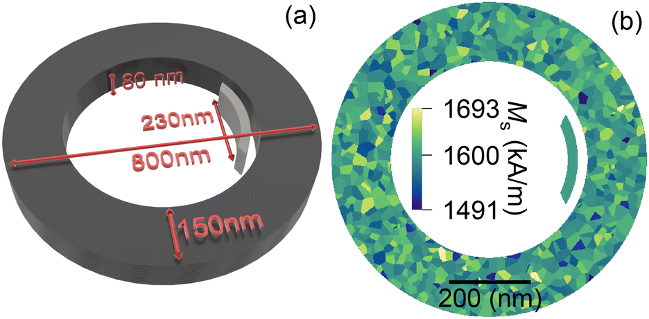 | ||
| Fig. 1 (a) Schematic representation of the system under consideration: the ferromagnetic nanoelement (NE) located inside a ferromagnetic ring (NR). The NE has a width of 25 nm, a thickness of 80 nm, and a length of 230 nm counting as a distance from edge to edge. (b) The grain structure representation used in the simulations. | ||
All simulations were carried out using MuMax3, a GPU-accelerated micromagnetic simulation program.36 To implement the system in the simulations, we discretized it with 512 × 512 × 7 cells with a cell size of ≈1.57 × 1.57 × 11.42 nm3 for a total size of 805 × 805 × 80 nm3 along the x, y and z axes, respectively. Since the magnetization is not uniform throughout the thickness and it would not be practical to show all 7 layers used in the simulations, we will present in the figures only the average magnetization across the thickness rather than a selected z-layer.
We used magnetic parameters from the experimental paper of Miyawaki et al.37 Those parameters were: saturation magnetization MS = 1600 kA m−1, uniaxial magnetocrystalline anisotropy along the z-axis (out-of-plane direction) with a constant K = 47 kJ m−3, and the exchange stiffness constant Aex = 21 pJ m−1.37 Using a Voronoi tessellation (see Fig. 1(b)), we have added magnetic grains in the NR to show that our results are robust even for imperfect materials. The grains are 20 nm on average and each of them has a random value of MS obtained from a normal distribution of mean 1600 kA m−1, and with a standard deviation σMS of 2% (32 kA m−1). The resulting MS is then assigned to 200 groups of randomly distributed grains inside a NR. We also reduced the exchange coupling between the grains uniformly by 5% as compared to the Aex value. The introduction of this inhomogeneity results in fully deterministic simulations for a non-NE configuration, always leading to a single VS with CW or CCW chirality, for a given pseudo-random number defining grains and distribution of MS among the grains (further details in the ESI†).
The simulations for the statistical analysis (shown in Fig. 2) for the parallel [Fig. 2(b)] and non-NE configuration [Fig. 2(a)] were run as follows. First, we apply a global external magnetic field Bext of 2 T along the y-axis, which saturates the NR and the NE if present, then we decrease Bext by 10 mT steps until we reach 0 mT. For every step, we use the conjugate gradient method to find the ground state of magnetization. For the antiparallel configuration [Fig. 2(c)], we could not apply such a strong external field as it would re-magnetize the NE in the parallel configuration. So here, we start from Bext = 100 mT, which is sufficient to maintain the OS for the NR, but not enough to switch the NE. In this case, we also had to set the initial NE magnetization in the opposite direction to the external field to achieve the desired configuration. Then, we demagnetized the system to 0 mT in 10 mT steps. Further details of the statistical analysis are in the ESI.†
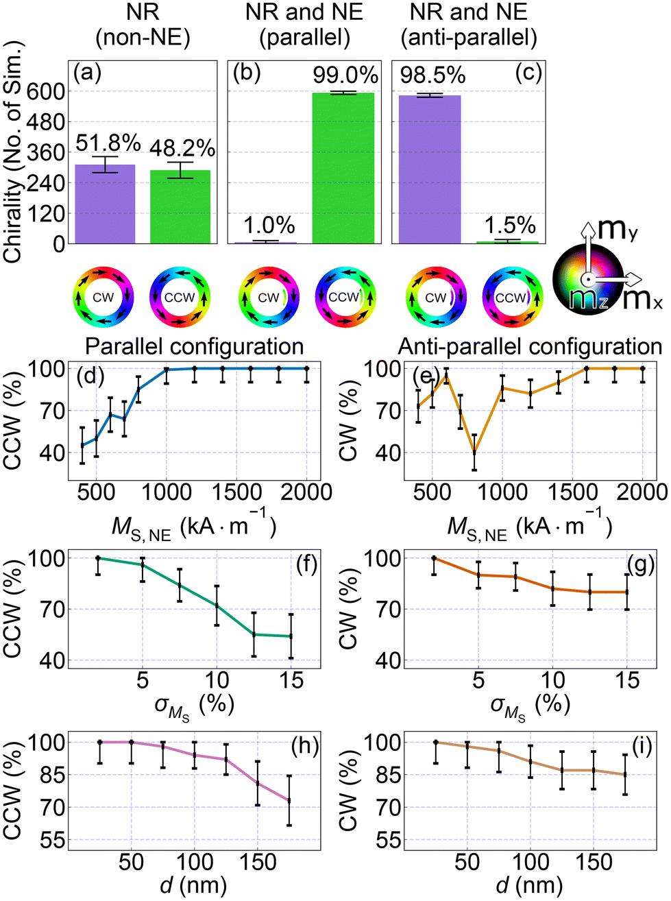 | ||
| Fig. 2 (a) The statistic of the 600 micromagnetic simulation results for the NR without the NE (non-NE configuration) with a different random distribution of parameters among the grains. (b and c) The statistics of the micromagnetic simulations with the same grain realizations, but for the NR with the NE in parallel and anti-parallel configurations, respectively. At the bottom, the static magnetization configurations in remanence are shown. Here, the color map indicates the magnetization vector orientation according to the diagram in the right-bottom corner. (d and e) Statistics of the chirality control with dependence on the decrease of the magnetization saturation of the NE. (f and g) Chirality control depends on the increase in the distribution of magnetization saturation in the grains. (h and i) Chirality control with dependence on the separation between the NE and the inner edge of the NR. Each point in (d–i) is based on 100 simulations. In all figures, the error bars mark the MOE calculated according to eqn (S1) and (S2) of the ESI.† | ||
3 Results and discussion
3.1 Chirality control demonstration
To show that the NE determines the final magnetization state of the NR, we conducted a statistical analysis of the re-magnetization of the NR with decreasing the external magnetic field according to the procedure described in the section Geometry and the simulation method. We ran 600 simulations for 3 configurations: non-NE configuration [Fig. 2(a)], parallel [Fig. 2(b)] and anti-parallel [Fig. 2(c)]. For each simulation, we used a different random seed, which resulted in a different organisation of the grain structure.In Fig. 2(a), we observe that the CW to CCW states are obtained in 51.8% and 48.2% of cases, respectively. The statistics change significantly when we introduce the NE. From Fig. 2(b) and (c), we see that we have almost full control of the VS chirality at remanence by the magnetization orientation of NE. 99.0% of the simulations show a CCW configuration with a NE magnetized parallel to Bext, and 98.5% of the simulations show a CW configuration for the opposite case.
In addition, we introduce the margin of error (MOE) for the statistical analysis, as shown in Fig. 2. The MOE is a formula used to calculate the range of possible values around the proportion of cases with the desired chirality, with a certain level of confidence. It takes into account the number of simulations, the standard deviation, and the desired level of confidence. The calculation of the MOE and the analysis are described in more detail in Section 1 of the ESI.† On the basis of these, we assume that a proportion of chirality control higher than 95% could be considered as full control of chirality.
In Fig. 2, we show the control of chirality with the NE having dependence on three parameters: magnetization saturation of the NE, magnetization distribution in the NR grains, and the NE position inside the NR. Due to a large number of cases, we decreased the number of simulations for each case to 100, supplemented with MOE analysis.
Fig. 2(d) and (e) show the effect of the magnetization saturation of the NE (MS,NE) on the chirality control for the parallel and anti-parallel configurations, respectively. We decreased the value of MS,NE from 1600 kA m−1 to 400 kA m−1 while keeping the value of MS in the NR unchanged, i.e., at MS = 1600 ± 5% kA m−1. For both configurations, we observed that lowering MS,NE reduces the degree of chirality control. This indicates that to control VS chirality the NE needs to have a sufficiently strong magnetic moment, which can be guaranteed by sufficiently large saturation magnetization or volume of the NE.
Interestingly, for the anti-parallel configuration shown in Fig. 2(e), the dependence is non-monotonic. When the magnetization of the NE is decreased to 800 kA m−1, it causes the NE to switch its magnetization to be parallel to the nearest part of the NR during the re-magnetization process, resulting in the loss of chirality control. We observed that 40% and 60% of the VSs are CW and CCW, respectively (similar to the non-NE configuration). However, when the magnetization of the NE is decreased to 600 kA m−1, we observed a significant increase in the number of CW states. This is due to the fragile interaction balance between the NE and the NR, which during demagnetization results in switching back the magnetization of the NE again to the antiparallel configuration below 50 mT, but before the switching field of the NR (25–30 mT). This is sufficient for VS chirality control. A more detailed description of this process requires separate investigations that are beyond the scope of this paper.
Fig. 2(f) and (g) show the statistics of the chirality with dependence on the σMS distribution in the grains, which was determined using Voronoi tessellation. For both NE configurations, the effect of the degree of chirality control decreases as σMS increases. However, for the antiparallel configuration, this process is much slower with respect to the parallel configuration. Fig. 2(h) and (i) show the statistics with dependence on the separation between the NE and the NR. With increasing distance, the effect of chirality control decreases for both configurations, but up to 150 nm, we still have over 80% of control. This indicates that by selecting the position of the NE relative to the edge of the NR, we can tune the occurrence of chirality of a given type to a given probability.
The results demonstrate that we have a stable systematic control of the VS chirality using the NE during the re-magnetization process. To elucidate the chirality control mechanisms, we performed a detailed hysteresis loop analysis.
3.2 Re-magnetization procedure
The NR and NE, made of the same material, exhibited different values of the switching field (in the NE, it was switching to the opposite magnetization orientation, and in the NR, we considered here the field which destroys VS, and it was 80 mT, as shown in Fig. 3(a), in non-NE configuration) due to differences in shape anisotropy. This means that the magnetization reversal process of the NE will occur at different magnetic fields compared to the NR.38 Furthermore, it is important to note that the coupled NR–NE system significantly alters the value of the NE switching field; it changes from HS = 94 mT to HS = 126 mT.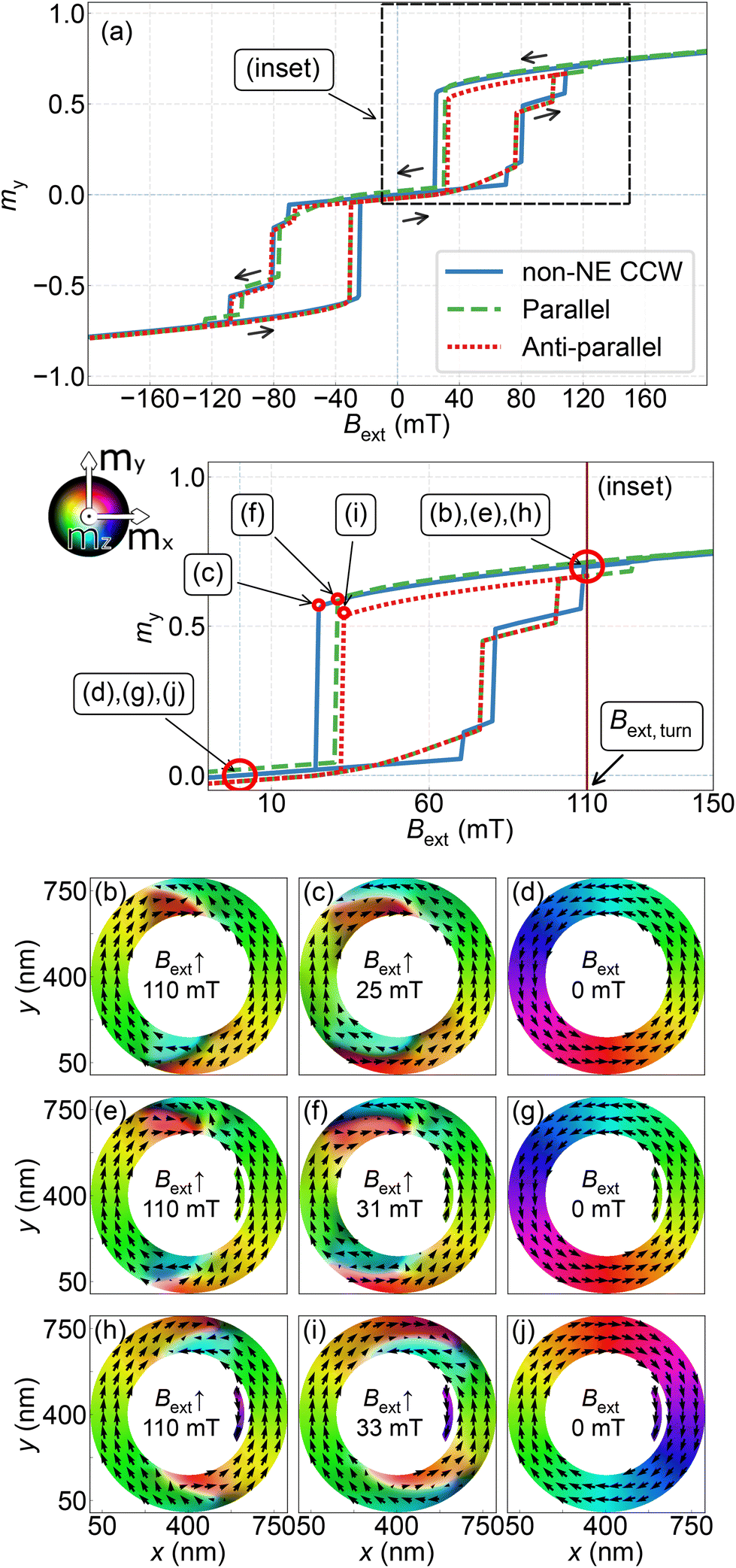 | ||
| Fig. 3 (a) and (a: inset) The simulations of the hysteresis loop, where, for the non-NE and parallel configurations, the simulations start at full saturation at −2000 mT to 2000 mT and opposite from 2000 mT to −2000 mT, and for the antiparallel configuration, the simulations start at full saturation at −2000 mT and are interrupted at point 110 mT, and then continue from 110 mT to −2000 mT. Magnetization configuration at the selected magnetic fields: (b–d) – in the non-NE configuration, (e–g) – parallel configuration, and (h–j) – antiparallel configuration. The magnetizations shown on the plot correspond to the opposite part of the hysteresis loop, either from 2000 to −2000 mT or from 110 to −2000 mT for the anti-parallel configuration. We use 1 mT step in hysteresis loop simulations. The color map for the magnetization orientation is shown on the left side of the plot (a: inset). | ||
We will analyse the hysteresis loop in the three scenarios related to the three configurations considered above. In the first scenario, non-NE configuration, the hysteresis loop is shown in Fig. 3(a) with a blue solid line. We start simulations by applying a large field of −2000 mT along the y direction, decreasing its magnitude to 0 mT, and then increasing it to the ring saturation in the opposite direction, i.e., 2000 mT (see a full hysteresis loop in Fig. S3 of the ESI†). This process is then repeated by reversing the direction of the field. The HTH and TTT DWs appear when the magnitude of the field is less than 400 mT. As the field is decreased further, the DWs start to deform. The magnetization structures at 110 and 25 mT are shown in Fig. 3(b) and (c), respectively. The re-magnetization of the right part of the ring occurs at −24 mT, and a CCW state stabilises at remanence, as shown in Fig. 3(d). However, the chirality of the ring depends on the random distribution of the grains, as shown in Fig. 2(a). Thus, for the other grain distributions, a CW state also may stabilize.
The second scenario is for the NR–NE system in the parallel configuration; we again start with full saturation at −2000 mT. The hysteresis loop is shown in Fig. 3(a) with a green dashed line, and develops in a similar way to that of the previous scenario. Fig. 3(e) shows the magnetization of the NR and NE at 110 mT. As shown in Fig. 3(f), the magnetization of the system is just before switching from an OS to a VS at −30 mT. This switching occurs at a higher field than for the non-NE configuration. In this scenario, the NE is located on the right side of the NR, leading to a CCW magnetization chirality at remanence, as shown in Fig. 3(g). Importantly, the final state in this scenario does not depend on the random distribution of the grains, as demonstrated in Fig. 2(b). Starting from a positive value of the external magnetic field, i.e., Bext = 2000 mT, we always reach a CCW chirality at remanence.
In the third scenario, we simulate a truncated hysteresis loop for the NR–NE system that allows for an antiparallel configuration, where the magnetization of the NE and the nearest side of the NR are aligned in opposite directions; see the red-dotted line in Fig. 3(a). We begin at an external magnetic field of −2000 mT along the y-direction and follow the main loop, decreasing the magnitude of the field as in the previous scenario. However, in this simulation, we interrupt the process at Bext,turn = 110 mT [Fig. 3(h)], when the magnetization of the NE and the nearest side of the NR are antiparallel. Then, we reverse the direction of the changes in the external magnetic field. Fig. 3(i) shows the magnetization at 33 mT, just before the demagnetization of the NR. The magnetization switches in the part of the ring closest to the NE, establishing a CW chirality in the ring, as shown in Fig. 3(j) and corresponding to Fig. 2(c).
The results show that regardless of the direction of the external magnetic field at the starting point of the field change, parallel or antiparallel to the direction of magnetization in the NE, the direction of magnetization in the NE is the same as the direction of magnetization of the nearest side of the NR at remanence, which determines the VS chirality.
The hysteresis loop simulations point out the feasibility of the experimental realisation of the VS chirality control in the NR with the uniaxial external magnetic field, according to the procedure described above. Important is that the switching field for the NE should not be smaller than the field of transition from the VS to the OS, and the stray field from the NE should be sufficiently strong. Both, as we have demonstrated, can be achieved by shaping the NE. Simulations show that the step in the magnetic field change is not important, as there is no statistical difference between a step of 1 mT and 10 mT.
Further conclusion is that the chirality control takes place at fields close to the switching field when one of the vertical parts of the ring changes the magnetization orientation as a result of DW motion in a defined direction. This is clearly visible in the movies provided in the ESI,† which show re-magnetisation in the NR. Thus, chirality is determined by the direction of movement of the DWs to the left or right part of the ring from the vertical symmetry axis, which is initiated by the magnetostatic interactions between the NR and the NE.
3.3 Discussion
The stray field produced by the NE interacts with the DWs and changes the internal field in the NR, and so introduces an additional element to the system that controls the direction of DW propagation. In Fig. 4, we schematically present DW changes with a decreasing magnetic field in the 3 scenarios of re-magnetization discussed in the previous sections.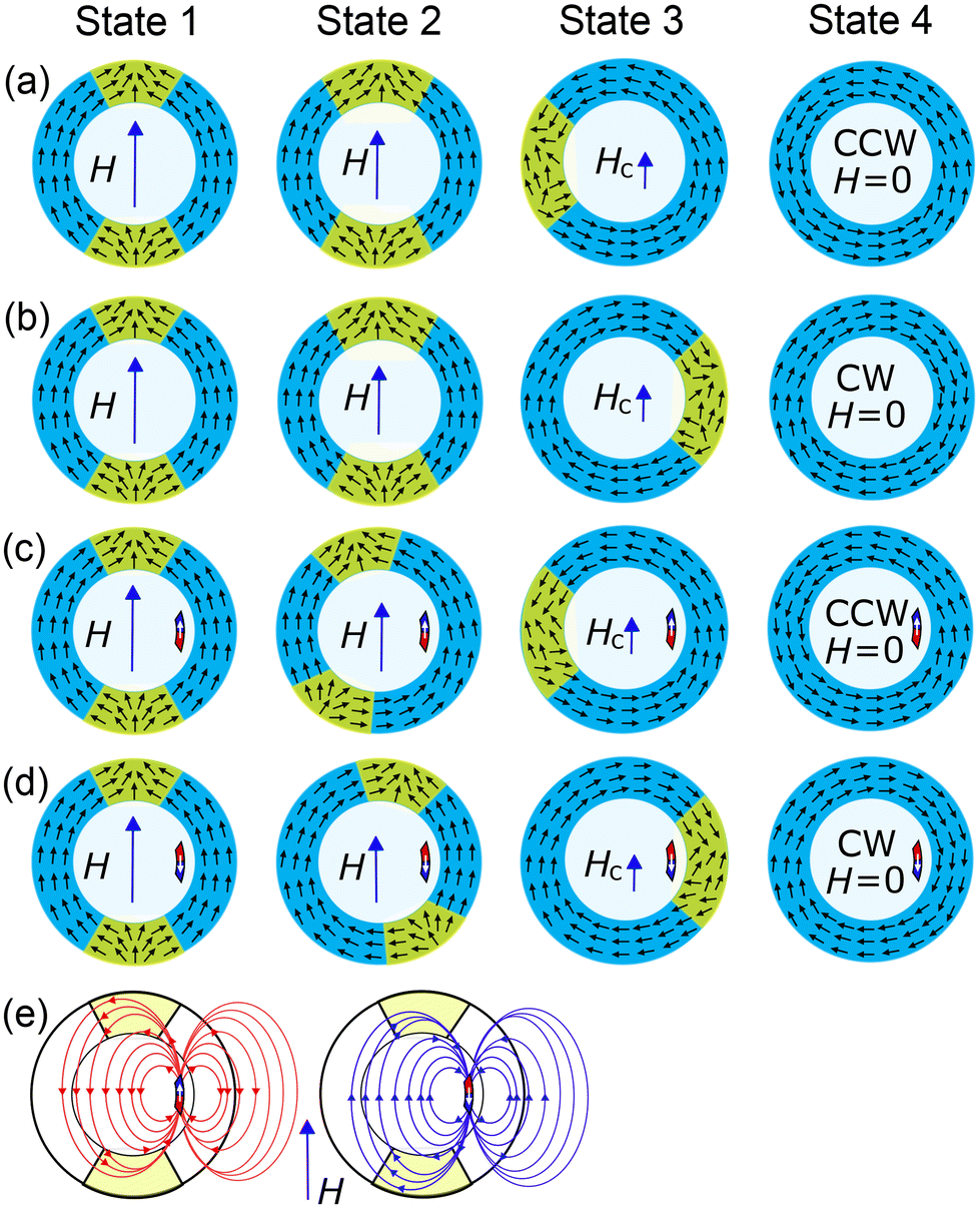 | ||
| Fig. 4 Schematic representation of the remagnetization process in a ring. Starting from the onion state (state 1), with decreasing magnetic field (applied vertically), the DWs move to the right or left (state 2), determining VS chirality at remanence (state 4) via annihilation at the switching field (state 3). The chirality of the VS (state 4) is not controlled in the non-NE case (a and b). With the NE magnetization oriented parallel (c) or antiparallel (d) to the external magnetic field in remanence, the ring determines the chirality, CCW and CW, respectively. (e) Schematic representation of the effect of the magnetostatic stray field from the NE on the DWs in the NR. | ||
In the non-NE configuration, Fig. 4(a) and (b), we can have two equivalent final configurations, CCW and CW, respectively. In state 1, the DWs are in the HTH and TTT configurations. State 2 shows the DW position in the decreased field, where the DWs are placed with small tilts to the external magnetic field. The movement of the DWs to the left or to the right are fully equivalent for the perfectly symmetric NR, which leads to an uncontrolled VS chirality. States 3 and 4 show the process of annihilation of DWs and the final state, CCW or CW, respectively.
Fig. 4(c and d) schematically illustrate the stages of DW evolution during the re-magnetization process for both parallel (c) and antiparallel (d) configurations. The process starts from state 1, where the ring has an onion state with HTH–TTT DWs in line with the external magnetic field. In state 2, the DWs begin to move, influenced by the magnetization of the NR. The NR induces a stray field, resulting in an asymmetrical distribution of the effective field between the left and right parts of the NR, as shown in Fig. 4(e) and Fig. S2(a and b) in the ESI.† For the parallel configuration of the NE and NR, the stray field from the NE (left part of Fig. 4(e)) pushes the DWs to the left side of the NR (state 3), ending with a CCW chirality in remanence (state 4). For the antiparallel configuration (right part of Fig. 4(e)), the stray field from the NE pushes the DWs to the right arm of the NR, causing the DWs to annihilate on the right side (state 3) and resulting in a CW chirality in remanence (state 4).
As described above, we break the circular symmetry of the magnetic system by introducing a NE, which creates a difference in the effective field distributions between the left and right parts of the NR and determines the direction of the DW motion (see also the ESI†).2,39 Thus, the stray field produced by the NE determines the direction of the torque exerted on the DWs in the NR. To measure the effect of the NE on the NR, we extracted magnetic torque from the micromagnetic simulations for all the cases presented above. We used the function that is defined in MuMax3, which returns Cartesian components of the magnetic torque in (T) units. The torque is saved immediately after the change in the external magnetic field, before starting the relaxation procedure. We transformed the torque for each discretization cell from the Cartesian to the 2D polar coordinate system. To obtain a single measure, we averaged the azimuthal component of the torque field across all spatial dimensions of the NR, resulting in a scalar,  , indicating whether the torque generated by the NE causes the NR's magnetization to rotate CW (
 < 0) or CCW (
 > 0).
> 0).
In Fig. 5 (left parts), we present  with dependence on the magnetic field for the configurations considered above. For simulations of the curves (1), (2), and (4), we imported a magnetization texture for some selected seeds from one of our previous analyses for the non-NE configuration at the field 100 mT [Fig. 2(a)], which ends with CCW VS. Then, we set the NE manually inside the ring with anti-parallel [curve (1)] and parallel [curve (2)] magnetization, and performed simulations with decreasing magnetic field, extracting τφ at each field step. The simulation (3) in the non-NE configuration was performed for other random seeds to show the re-magnetization of the NR to the CW state. We see that the sign of
  at fields just before the switching field points out the VS chirality in remanence in all the presented configurations. Moreover, for case (1), where the magnetization orientation of the NE was artificially reversed at the starting field 100 mT, the
  from the positive value changes the sign at smaller fields, and ends with negative values expected for CW chirality at this configuration. More detailed illustrations of the evolution of the torque in the considered cases are present in animation 2 of the ESI.†
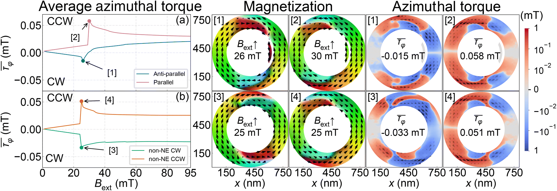 | ||
| Fig. 5 Numerical simulations of the azimuthal component of the averaged torque in the ring with dependence on the magnetic field. In (a), we show the results of two simulations for the anti-parallel [curve (1)] and parallel [curve (2)] magnetization of the NE with respect to the magnetic field, which ends with CW and CCW VSs, respectively. In both simulations, the same random seed was used. (b) The results for the non-NE configuration with two different random seed numbers, which determine the chirality of the VS, CW (3) and CCW (4) in remanence. For (4), we used the same random seed as in (1) and (2) in the simulations. On the right part of the plots, the magnetization configuration and local distribution of the azimuthal component of the torque in the NR are shown for the four considered cases, at the fields just before the switching (marked by dots on the left plots). We use 1 mT step in the simulations. The color map for the magnetization orientation is the same as that shown in Fig. 2. | ||
4 Conclusions
In summary, we have demonstrated with micromagnetic simulations the systematic control of vortex chirality in a symmetric ferromagnetic ring by a ferromagnetic nanoelement placed inside the ring. The NE, by exerting a stray magnetostatic field, changes the symmetry of HTH–TTT DWs in the onion state, and during the re-magnetization process determines the direction of the DW movement and finally VS chirality in remanence. To control chirality, the NE requires sufficiently strong shape anisotropy to maintain a monodomain state and to have a switching field higher than the switching field of the NR (without the NE). In addition, the NE should have a sufficiently large magnetic moment (through large saturation magnetization or volume) to create a stray magnetostatic field that will determine the direction of DW motion. We show that this can be achieved by making the NE with a material in a shape similar to the part of the inner side of the ring, which simplifies the eventual fabrication process. In addition, we demonstrated the resistance of this method to the variability of geometric and material parameters of the system and random NR disturbances. All this makes the experimental implementation of the proposed system possible using the existing technologies and makes it useful for spintronic and magnonic applications.Data availability
Source files for this paper, including simulation scripts, are available at ZENODO at https://zenodo.org/record/8006816.Conflicts of interest
There are no conflicts to declare.Acknowledgements
The research was co-financed by the National Science Center of Poland, project no. 2020/37/B/ST3/03936. MM acknowledges funding from the Slovak Grant Agency APVV (grant no. APVV-19-0311(RSWFA)), and is supported by the Research & Innovation Operational Programme funded by the ERDF-ITMS project code 313021T081. The simulations were partially performed at the Poznan Supercomputing and Networking Center (grant no. 398).Notes and references
- J.-G. Zhu, Y. Zheng and G. A. Prinz, J. Appl. Phys., 2000, 87, 6668–6673 CrossRef CAS.
- M. Kläui, C. A. F. Vaz, L. Lopez-Diaz and J. A. C. Bland, J. Phys.: Condens. Matter, 2003, 15, R985 CrossRef.
- C. A. Vaz, T. J. Hayward, J. Llandro, F. Schackert, D. Morecroft, J. A. Bland, M. Kläui, M. Laufenberg, D. Backes, U. Rüdiger, F. J. Castño, C. A. Ross, L. J. Heyderman, F. Nolting, A. Locatelli, G. Faini, S. Cherifi and W. Wernsdorfer, J. Phys.: Condens. Matter, 2007, 19, 255207 CrossRef.
- C. A. Ross, F. J. Castaño, W. Jung, B. G. Ng, I. A. Colin and D. Morecroft, J. Phys. D: Appl. Phys., 2008, 41, 113002 CrossRef.
- Y. Zheng and W. J. Chen, Rep. Prog. Phys., 2017, 80, 086501 CrossRef PubMed.
- T. J. Hayward, T. A. Moore, D. H. Y. Tse, J. A. C. Bland, F. J. Castaño and C. A. Ross, Phys. Rev. B: Condens. Matter Mater. Phys., 2005, 72, 184430 CrossRef.
- M.-A. Mawass, K. Richter, A. Bisig, R. M. Reeve, B. Krüger, M. Weigand, H. Stoll, A. Krone, F. Kronast, G. Schütz and M. Kläui, Phys. Rev. Appl., 2017, 7, 044009 CrossRef.
- J. Podbielski, F. Giesen and D. Grundler, Phys. Rev. Lett., 2006, 96, 167207 CrossRef CAS PubMed.
- I. Neudecker, M. Kläui, K. Perzlmaier, D. Backes, L. J. Heyderman, C. A. F. Vaz, J. A. C. Bland, U. Rüdiger and C. H. Back, Phys. Rev. Lett., 2006, 96, 057207 CrossRef CAS PubMed.
- F. Montoncello, L. Giovannini, F. Nizzoli, H. Tanigawa, T. Ono, G. Gubbiotti, M. Madami, S. Tacchi and G. Carlotti, Phys. Rev. B: Condens. Matter Mater. Phys., 2008, 78, 104421 CrossRef.
- E. Rapoport, D. Montana and G. S. Beach, Lab Chip, 2012, 12, 4433–4440 RSC.
- R. W. Dawidek, T. J. Hayward, I. T. Vidamour, T. J. Broomhall, G. Venkat, M. A. Mamoori, A. Mullen, S. J. Kyle, P. W. Fry, N. J. Steinke, J. F. Cooper, F. Maccherozzi, S. S. Dhesi, L. Aballe, M. Foerster, J. Prat, E. Vasilaki, M. O. Ellis and D. A. Allwood, Adv. Funct. Mater., 2021, 31, 2008389 CrossRef CAS.
- F. Q. Zhu, G. W. Chern, O. Tchernyshyov, X. C. Zhu, J. G. Zhu and C. L. Chien, Phys. Rev. Lett., 2006, 96, 027205 CrossRef CAS PubMed.
- W. Jung, F. J. Castaño and C. A. Ross, Phys. Rev. Lett., 2006, 97, 247209 CrossRef CAS PubMed.
- S. Prosandeev, I. Ponomareva, I. Kornev and L. Bellaiche, Phys. Rev. Lett., 2008, 100, 047201 CrossRef CAS PubMed.
- R. Nakatani, T. Yoshida, Y. Endo, Y. Kawamura, M. Yamamoto, T. Takenaga, S. Aya, T. Kuroiwa, S. Beysen and H. Kobayashi, J. Appl. Phys., 2004, 95, 6714–6716 CrossRef CAS.
- S. R. Bowden, K. K. L. Ahmed and U. J. Gibson, Appl. Phys. Lett., 2007, 91, 232505 CrossRef.
- E. Saitoh, M. Kawabata, K. Harii, H. Miyajima and T. Yamaoka, J. Appl. Phys., 2004, 95, 1986 CrossRef CAS.
- C. H. Huang, N. J. Cheng, F. S. Wu, J. C. Wu and L. Horng, IEEE Trans. Magn., 2012, 48, 3648–3650 Search PubMed.
- K. Richter, A. Krone, M.-A. Mawass, B. Krüger, M. Weigand, H. Stoll, G. Schütz and M. Kläui, Phys. Rev. B, 2016, 94, 024435 CrossRef.
- D. Schönke, R. M. Reeve, H. Stoll and M. Klaüi, Phys. Rev. Appl., 2020, 14, 034028 CrossRef.
- S.-Y. Lin, Y.-H. Lin, T.-R. Ger, H.-T. Huang and Z.-H. Wei, J. Appl. Phys., 2011, 109, 07D507 CrossRef.
- C.-P. Lee, C.-J. Hsu and M.-F. Lai, IEEE Trans. Magn., 2011, 47, 505–508 CAS.
- J. Li, S. Zhang, C. Grigas, R. Misra, J. Bartell, V. H. Crespi and P. Schiffer, AIP Adv., 2012, 2, 012136 CrossRef.
- M. Kläui, J. Rothman, L. Lopez-Diaz, C. A. F. Vaz, J. A. C. Bland and Z. Cui, Appl. Phys. Lett., 2001, 78, 3268–3270 CrossRef.
- J. Tóbik, V. Cambel and G. Karapetrov, Sci. Rep., 2015, 5, 12301 CrossRef PubMed.
- M. Schneider, H. Hoffmann and J. Zweck, Appl. Phys. Lett., 2001, 79, 3113–3115 CrossRef CAS.
- Y. Zhang, C. Wang, H. Huang, J. Lu, R. Liang, J. Liu, R. Peng, Q. Zhang, Q. Zhang, J. Wang, L. Gu, X.-F. Han, L.-Q. Chen, R. Ramesh, C.-W. Nan and J. Zhang, Sci. Bull., 2020, 65, 1260–1267 CrossRef PubMed.
- A. Haldar and A. O. Adeyeye, Appl. Phys. Lett., 2015, 106, 032404 CrossRef.
- C. Nam, M. D. Mascaro and C. A. Ross, Appl. Phys. Lett., 2010, 97, 012505 CrossRef.
- E. Tadmor, Y. J. Rosen, I. K. Schuller and S. Bar-Ad, J. Appl. Phys., 2012, 112, 103903 CrossRef.
- A. Sarella, A. Torti, M. Donolato, M. Pancaldi and P. Vavassori, Adv. Mater., 2014, 26, 2384–2390 CrossRef CAS PubMed.
- D. Suess, A. Bachleitner-Hofmann, A. Satz, H. Weitensfelder, C. Vogler, F. Bruckner, C. Abert, K. Prügl, J. Zimmer, C. Huber, S. Luber, W. Raberg, T. Schrefl and H. Brückl, Nat. Electron., 2018, 1, 362–370 CrossRef.
- M. Jotta Garcia, J. Moulin, S. Wittrock, S. Tsunegi, K. Yakushiji, A. Fukushima, H. Kubota, S. Yuasa, U. Ebels, M. Pannetier-Lecoeur, C. Fermon, R. Lebrun, P. Bortolotti, A. Solignac and V. Cros, Appl. Phys. Lett., 2021, 118, 122401 CrossRef CAS.
- I. T. Vidamour, M. O. Ellis, D. Griffin, G. Venkat, C. Swindells, R. W. Dawidek, T. J. Broomhall, N. J. Steinke, J. F. Cooper, F. Maccherozzi, S. S. Dhesi, S. Stepney, E. Vasilaki, D. A. Allwood and T. J. Hayward, Nanotechnology, 2022, 33, 485203 CrossRef PubMed.
- A. Vansteenkiste, J. Leliaert, M. Dvornik, M. Helsen, F. Garcia-Sanchez and B. V. Waeyenberge, AIP Adv., 2014, 4, 107133 CrossRef.
- T. Miyawaki, K. Toyoda, M. Kohda, A. Fujita and J. Nitta, Appl. Phys. Lett., 2006, 89, 122508 CrossRef.
- J. Li, S. Dong, W. C. Yue, Z. Yuan, Z. L. Xiao, Y. Y. Lyu, T. T. Wang, C. Li, C. Wang, W. B. Xu, Y. Dong, H. Wang, P. Wu, W. K. Kwok and Y. L. Wang, AIP Adv., 2021, 11, 045010 CrossRef.
- M. Kläui, J. Phys.: Condens. Matter, 2008, 20, 313001 CrossRef.
Footnote |
| † Electronic supplementary information (ESI) available. See DOI: https://doi.org/10.1039/d3nr00582h |
| This journal is © The Royal Society of Chemistry 2023 |