
 Open Access Article
 This Open Access Article is licensed under a Creative Commons Attribution-Non Commercial 3.0 Unported Licence
Valid design and evaluation of cathode and anode materials of aqueous zinc ion batteries with high-rate capability and cycle stability†
Se Hun
Lee‡
a,
Juyeon
Han‡
b,
Tae Woong
Cho‡
a,
Gyung Hyun
Kim
a,
Young Joon
Yoo
a,
JuSang
Park
a,
Young Jun
Kim
a,
Eun Jung
Lee
a,
Sihyun
Lee
c,
Sungwook
Mhin
 c,
Sang Yoon
Park
*a,
Jeeyoung
Yoo
*b and
Sang-Hwa
Lee
*a
c,
Sang Yoon
Park
*a,
Jeeyoung
Yoo
*b and
Sang-Hwa
Lee
*a
aAdvanced Institute of Convergence Technology, Seoul National University, Suwon 16229, Republic of Korea. E-mail: yoonpark77@snu.ac.kr; jyoo@knu.ac.kr; sanghwalee@snu.ac.kr
bSchool of Energy Engineering, Kyungpook National University, Daegu, 41566, Republic of Korea
cAdvanced Materials Engineering, Kyonggi University, Suwon 16227, Republic of Korea
First published on 4th February 2023
Abstract
Although non-aqueous lithium-ion batteries have a high gravimetric density, aqueous zinc-ion batteries (ZIBs) have recently been in the spotlight as an alternative, because ZIBs have characteristics such as high volumetric density, high ionic conductivity, eco-friendliness, low cost, and high safety. However, the improvement in electrochemical performance is limited due to insufficient rate capability and severe cycle fading of the vanadium-oxide-based cathode and zinc-metal-based anode material, which are frequently used as active materials for ZIBs. In addition, complex methods are required to prepare high-performance cathode and anode materials. Therefore, a simple yet effective strategy is needed to obtain high-performance anodes and cathodes. Herein, an ammonium vanadate nanofiber (AVNF) intercalated with NH4+ and H2O as a cathode material for ZIBs was synthesized within 30 minutes through a facile sonochemical method. In addition, an effective Al2O3 layer of 9.9 nm was coated on the surface of zinc foil through an atomic layer deposition technique. As a result, AVNF//60Al2O3@Zn batteries showed a high rate capability of 108 mA h g−1 even at 20 A g−1, and exhibited ultra-high cycle stability with a capacity retention of 94% even after 5000 cycles at a current density of 10 A g−1.
1 Introduction
For decades, lithium-ion batteries (LIBs) have been a major energy storage device in the commercial electronics market due to their high energy transmission efficiency and high energy density. However, concerns about high cost, safety, and environmental contamination are growing, and alternative energy devices to LIBs are needed.1–3 Zinc ion batteries (ZIBs), a type of multivalent ion battery, have a high theoretical gravimetric and volumetric density of 820 mA h g−1 and 5854 A h L−1 of zinc metal, respectively. In addition, they are more cost efficient (∼2.4 USD kg−1) than lithium (19.2 USD) due to the large amount of Zn reserves (300 times higher than lithium). Zn metal has a lower redox potential (−0.76 eV) than the standard hydrogen electrode (SHE), which makes it suitable for aqueous ZIBs.4–7 In addition, ZIBs, which use water as the electrolyte, are relatively safe from flammability issues, and have an ionic conductivity of ∼1 S cm−1, which is 100 times higher than that of non-aqueous batteries.8–14Vanadium pentoxide (V2O5) has been studied as a cathode material for ZIBs due to its appropriate interlayer distance of 0.43 nm, which is suitable for Zn2+ ion intercalation.15 Recent studies have revealed the specific capacity of V2O5 to be 375–470 mA h g−1.16–18 However, multiple Zn2+ ion intercalation induces deformation of the V2O5 structure, thus causing degeneration in the specific capacity and rate capability.19 Recently, the synthesis of metal cation inserted electrodes has been studied to prevent the deformation of materials. Mai et al. reported Na+ ion pre-intercalated V2O5, which exhibited a cycle stability of 93% (of the initial capacity retention) after 1000 cycles of charging/discharging at 1.0 A g−1.20 In addition, methods for synthesizing vanadate nanofibers pre-intercalated with H2O and metal cationic species by various methods, such as hydrothermal water, sol–gel, surfactant-assisted templating, and electrochemical methods have been studied.21–24
In our previous work, we presented a simple and efficient sonochemical method capable of synthesizing ammonium vanadate nanofiber (AVNF: (NH4)2V6016·1.5H2O) to overcome the aforementioned problems.25–27 The AVNFs were synthesized in 30 min using sonochemistry. The synthesis mechanism of this simple vanadate nanofiber is accompanied by a polyoxometalate reaction. The one-dimensional morphology of vanadate nanofiber synthesized using the very simple method can secure high capacity due to the expansion of the active site by the large specific surface area in the electrochemical reaction. In addition, AVNFs with this type of one-dimensional morphology have higher electrical conductivity than bulk vanadium oxide, which affects theimprovement in rate capability. However, during the charging and discharging process of ZIBs, dendrites are easily formed on the Zn anode, increasing the internal resistance by dead Zn, decomposing the electrolyte, and lowering the efficiency. This phenomenon leads to unstable cycle stability and low rate capability due to the formation of heterogeneous ion pathways during repeated cycles.28 Furthermore, excessively formed dendrites penetrate through the separator and induce short circuits and a rapid decrease in energy density.29 To overcome this problem, studies on dendrite prevention in Zn-based alloys, surface morphology treatment, hetero structure with conductive layer, and electrolyte optimization have been reported.30–36 For example, He et al. reported retention of 89.4% by ZIBs with Al2O3 deposition on Zn after 1000 cycles.37 Dai et al. showed the Al2O3 effect of the discharging capacity, but the cycling stability was lowered.38 The retention improved from 51.92% to 76.11% of Al2O3 on Zn-V2O5 for 1000 cycles.39 Therefore, in order to reach high rate capability and cycle stability in ZIBs, the anode and cathode must be reformed simultaneously, and this reforming method must be simple and effective.
In our study, ammonium vanadate nanofibers (AVNF) were synthesized very quickly and efficiently using the sonochemical method as a cathode active material. In addition, the optimal Al2O3 layer thickness on zinc foil was found to minimize cell polarization and form a stable ion pathway through atomic layer deposition as an anode. Thus, the thickness of the optimized Al2O3 layer was found to be 9.9 nm. AVNF has a one-dimensional structure, so it can secure a wide active site, and ammonium cation and H2O intercalated in the vanadate structure can express high specific capacity through the roles of pillars and lubricants, respectively. The Al2O3@Zn anode mechanically inhibits dendrite growth to form a stable and reversible ion pathway during the charging and discharging process, resulting in improved cycle stability. The hydrophilicity of Al2O3 reduces charge transfer resistance and also improves rate capability. The electrochemical properties of a coin cell with an AVNF cathode and Al2O3-coated Zn electrode (AVNF//Al2O3@Zn) were analysed. As a result, AVNF//60Al2O3@Zn, whose numerical value indicating the number of ALD cycles for batteries showed a high rate capability of 108 mA h g−1 even at 20 A g−1, and exhibited ultra-high cycle stability with a capacity retention of 94% even after 5000 cycles with mossy-like dendrite formation at a current density of 10 A g−1.
2 Experimental
2.1. Synthesis of AVNF cathode
Fig. 1(a) shows a schematic of the AVNF synthesis. All chemical reagents, including vanadium pentoxide (V2O5, 99%) and ammonium persulfate ((NH4)2S2O8, 98%), were purchased from Sigma-Aldrich. Deionized (DI) water was used as the solvent for the synthesis of AVNF (18.2 mΩ cm−1, Milli-Q Plus system, Millipore, France). A yellow dispersion was prepared by dissolving 0.4 g of vanadium pentoxide (V2O5, 2.2 mmol) and 0.2 g of APS (0.88 mmol) in 100 mL of DI water. A sonicator (20 kHz and 500 W) equipped with a titanium tip was immersed in the dispersion to a depth of 1.5 cm and it was sonicated for 30 min. After the ultrasonic reaction was over, the colour of the solution changed from yellow to dark red. Subsequently, the AVNF solid product was obtained through filtration using ethanol and water. The obtained solid product of AVNF was dried in a vacuum oven for 12 hours at 60 °C. The morphologies and energy dispersive spectroscopy (EDS) data of V2O5 and the synthesized AVNF sample were measured with a scanning electron microscope (SEM). Changes in the vibrational, functional, and chemical structures of the bulk V2O5 and AVNF were analysed by measuring the FT-IR spectra. The specific surface area and pore size distribution were estimated by measuring the nitrogen adsorption curves of V2O5 and AVNF at 77.3 K. The pore diameters of the samples were determined by linear fitting of a Brunauer–Emmett–Teller (BET) plot. The crystal structure and weight loss depending on the temperature were analysed by measuring the X-ray diffraction (XRD) patterns and thermogravimetric analysis (TGA) curves. The chemical composition of AVNF was estimated by measuring the X-ray photoelectron spectroscopy (XPS) data. | ||
| Fig. 1 A schematic of the preparation of AVNF and Al2O3@Zn. (a) A scheme for the synthesis of ammonium vanadate nanofiber (AVNF: (NH4)2V6O16·1.5H2O) from V2O5 using the sonochemical method. (b) A scheme for the deposition of Al2O3 formed by the reaction of TMA (trimethylaluminum, Al(CH3)3) and distilled water (H2O) in an ALD cycle. | ||
2.2. Synthesis of Al2O3@Zn anode
The Al2O3@Zn anode was prepared by atomic layer deposition (ALD). Al2O3 was formed by chemical reaction of the trimethylaluminum (TMA, Al(CH3)3) precursor with distilled water during the ALD process. To investigate the dependence of the electrochemical performance on the thickness of Al2O3, Al2O3@Zn samples were prepared under different numbers of ALD cycles (20 to 100 cycles). An ALD cycle induces chemical reactions of TMA (precursor) and H2O (reactant), which are progressively injected into the chamber with Ar purging for each injection. The thicknesses of a sample is dependent on the number of ALD cycles. Evidence of the Al2O3 layer was obtained by measuring the XPS spectra and XRD patterns. The thickness of the Al2O3 layer was determined by observing the cross-section using SEM and X-ray reflectivity (XRR) data. For estimation of the thickness of Al2O3@Zn by ellipsometry, the complex refractive index values were determined based on the Al2O3@Si results.2.3. Electrochemical tests
The AVNF cathode was prepared using AVNF, carbon black (Super P, TIMCAL), and polyvinylidene difluoride (PVdF, HSV 900, Kynar) with a mass ratio of 7![[thin space (1/6-em)]](https://www.rsc.org/images/entities/char_2009.gif) :2:1. The powders were mixed with N-methyl pyrrolidone (NMP, Sigma-Aldrich) to make a homogenous slurry using a planetary centrifugal mixer (AR-100, Thinky Corporation). The slurry was uniformly coated on carbon paper with a loading mass of 1.0–1.2 mg. The aqueous electrolyte was prepared by dissolving 2.58 M zinc trifluoromethanesulfonate (Zn(OTf)2, Alfa Aesar, 98%) in DI water. A Zn–Zn symmetric cell and AVNF-Zn half-cell were assembled using a CR2032 coin cell. A glass fiber separator (GF/A, Whatman) and 150 μL of 2.58 M Zn(OTf)2 were used. All the electrochemical analyses were performed under ambient conditions. The Zn–Zn symmetric cells were tested at 1 mA cm−2 with a fixed capacity of 1 mA h cm−2. Tests of the Zn–Zn symmetric cell and AVNF//Zn half-cell were conducted using a battery cycler (WBCS 3000 L, WonATech). Electrochemical impedance spectroscopy (EIS) measurements were performed from 1 MHz to 0.1 Hz with an amplitude of 5 mV. EIS was employed on an electrochemical workstation (CHI 660E, Chinese Science, Day Ltd). A half-cell with an AVNF cathode was tested over the voltage range of 0.2–1.8. Cycle performance was measured at a current density of 10 A g−1 after three pre-cycles at 0.5, 1, 2, 4, 8 A g−1 to stabilize the cell.
:2:1. The powders were mixed with N-methyl pyrrolidone (NMP, Sigma-Aldrich) to make a homogenous slurry using a planetary centrifugal mixer (AR-100, Thinky Corporation). The slurry was uniformly coated on carbon paper with a loading mass of 1.0–1.2 mg. The aqueous electrolyte was prepared by dissolving 2.58 M zinc trifluoromethanesulfonate (Zn(OTf)2, Alfa Aesar, 98%) in DI water. A Zn–Zn symmetric cell and AVNF-Zn half-cell were assembled using a CR2032 coin cell. A glass fiber separator (GF/A, Whatman) and 150 μL of 2.58 M Zn(OTf)2 were used. All the electrochemical analyses were performed under ambient conditions. The Zn–Zn symmetric cells were tested at 1 mA cm−2 with a fixed capacity of 1 mA h cm−2. Tests of the Zn–Zn symmetric cell and AVNF//Zn half-cell were conducted using a battery cycler (WBCS 3000 L, WonATech). Electrochemical impedance spectroscopy (EIS) measurements were performed from 1 MHz to 0.1 Hz with an amplitude of 5 mV. EIS was employed on an electrochemical workstation (CHI 660E, Chinese Science, Day Ltd). A half-cell with an AVNF cathode was tested over the voltage range of 0.2–1.8. Cycle performance was measured at a current density of 10 A g−1 after three pre-cycles at 0.5, 1, 2, 4, 8 A g−1 to stabilize the cell.
3 Results and discussion
3.1. Structure and morphology of AVNF
AVNF can be synthesized in less than 30 min using the sonochemical method shown in Fig. 1. When ultrasonic waves are irradiated onto a solution, a sonochemical reaction is induced by acoustic cavitation in the liquid. Acoustic cavitation occurs in three stages: nucleation, growth, and bubble implosive collapse.40 The chemical reaction accelerates the acoustic cavitation of the liquid by ultrasonic irradiation, thus reducing the time required to synthesize the vanadate nanofiber. The nucleation of cavitation bubbles, such as the microbubbles between suspended particles, begins at weak points, and when microbubbles are exposed to the large negative pressure of acoustic waves, cavitation bubbles are created. As the generated cavitation bubbles undergo repeated compression and rarefaction, they grow and expand until the negative pressure indicates the maximum value. In the collapse step, extreme temperatures of approximately 5000 K and enormous pressures of approximately 200–500 atm occur in the liquid. The explosion points where these extreme environments occur are called ‘hot spots’.41 All these processes take place within a few picoseconds, and these extreme conditions cause the breakdown and recombination of chemical bonds in the material within a short time. Therefore, the reaction time of the sonochemical method is shorter than that of the surfactant-assisted templating, reflux, hydrothermal, sol–gel, and electrochemical deposition methods. In this sonochemical reaction, the growth mechanism of ammonium vanadate fibers can be explained by the olation and oxolation reactions of the precursors formed by internal proton transfer of vanadium six-coordinated by water molecules.42 At this time, when the solution reaches a certain pH, the reaction rate of olation becomes faster than that of oxolation. Therefore, the growth direction of the precursor is biased toward olation rather than oxolation. Thus, the fibrous morphology of ammonium vanadate is formed.The AVNF synthesized by the sonochemical method according to the previously described mechanism was investigated by comparing the SEM images with V2O5, as shown in Fig. 2(a) and (b). SEM images at various magnifications in Fig. 2(a) show bulk V2O5 in disordered form. In bulk vanadium oxide, primary particles of approximately 0.2 μm form secondary particles of approximately 1 to 3 μm. In addition, through EDS mapping, it was confirmed that the vanadium pentoxide sample was composed of only elements V and O. The SEM images in Fig. 2(b) show the formation of ammonium vanadate with nanofiber morphology after 30 min of the sonication reaction. The diameters of the synthesized AVNFs were in the order of nanometers and had a length of more than 4 μm. In addition, through the EDS mapping data in Fig. 2(b), it was confirmed that the AVNFs containing V, O, and N elements were well synthesized by the sonochemical phenomena. Among these elements, the N atom is due to NH4+, which exists between crystal planes of vanadate nanofiber and can improve electrical conductivity by proton transfer, as observed in previous studies.42
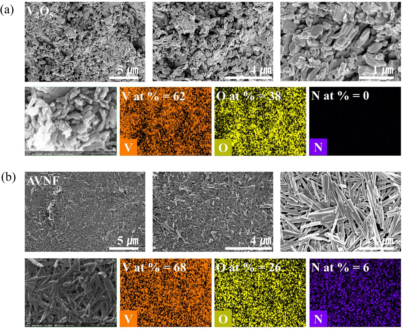 | ||
| Fig. 2 Surface morphologies and quantitative analysis of V2O5 and the ammonium vanadate nanofiber (AVNF: (NH4)2V6O16·1.5H2O). SEM images and EDS data for V2O5 and AVNF are shown in (a) and (b), respectively. | ||
Fig. 3 shows the crystal structure of AVNF and detailed fiber morphology observed through HR-TEM image analysis at various magnifications. It can be confirmed that the diameter of the synthesized AVNF after 30 min of sonication reaction was exactly 15 nm. In addition, the interplanar spacing of the (002) planes of AVNF were found to be 9.1 Å. This result is confirmed through Bragg's law in the XRD analysis.
 | ||
| Fig. 3 TEM images of the AVNF. The fiber thickness and interlayer distance are 15 nm and 9.1 Å, respectively, as shown in the figure. | ||
As shown in Fig. 4(a), the vibrational, functional, and chemical structures changes in bulk V2O5 and AVNF were demonstrated by FT-IR spectra.43 The V![[double bond, length as m-dash]](https://www.rsc.org/images/entities/char_e001.gif) O stretching of vanadate appeared at 992 and 962 cm−1 in Fig. 4(a).44 In addition, the 791 and 843 cm−1 bands are assigned to VO and V–O–V bending bands, respectively.45 These shifts in the VO and V–O–V bands are due to the charge interaction of the ammonium cation with the oxygen bound to the V element. The peak of 710 cm−1 shows the V–OH2 stretching band by the coordinated water molecule.46 The bands at 3204 and 1418 cm−1 indicate the asymmetric stretching and symmetric bending vibrations of the ammonium cation, respectively, which was inserted in the vanadate interlayer.47 In addition, 3553 and 1600 cm−1 are assigned to stretching of water molecules and their bending band, respectively.48 As a result, it can be confirmed that water molecules and ammonium ions are added into the AVNF structure to form a chemical structure when V2O5 changes to AVNF.
O stretching of vanadate appeared at 992 and 962 cm−1 in Fig. 4(a).44 In addition, the 791 and 843 cm−1 bands are assigned to VO and V–O–V bending bands, respectively.45 These shifts in the VO and V–O–V bands are due to the charge interaction of the ammonium cation with the oxygen bound to the V element. The peak of 710 cm−1 shows the V–OH2 stretching band by the coordinated water molecule.46 The bands at 3204 and 1418 cm−1 indicate the asymmetric stretching and symmetric bending vibrations of the ammonium cation, respectively, which was inserted in the vanadate interlayer.47 In addition, 3553 and 1600 cm−1 are assigned to stretching of water molecules and their bending band, respectively.48 As a result, it can be confirmed that water molecules and ammonium ions are added into the AVNF structure to form a chemical structure when V2O5 changes to AVNF.
 | ||
| Fig. 4 The chemical and crystal structures of V2O5 and ammonium vanadate nanofiber (AVNF: (NH4)2V6O16·1.5H2O) characterized by (a) the FT-IR spectra, (b) nitrogen isotherm curves, (c) XRD patterns, and TGA and DTG curves. | ||
The nitrogen isotherm curves of V2O5 and AVNF powder are shown in Fig. 4(b). The nitrogen isotherm curve for V2O5 resembles a type II isotherm curve, which is the typical shape for an adsorbent with a very low specific surface area. However, at the beginning of the BET curve for AVNF, the absorbed amount and volume are higher than those of V2O5 due to the increase in the specific surface area. The values of the specific surface areas of V2O5 and AVNF were estimated to be 5.2 and 61.5 m2 g−1, respectively, corresponding to an increase in the pore volume from 0.012 to 14.1 cm3 g−1.
XRD measurements were conducted to analyse the crystal structure of V2O5 and AVNF, as shown in Fig. 4(c). Fig. 4(c) displays the XRD pattern of V2O5, which exhibits peaks that can be attributed to the crystalline phase of V2O5 [JCPDS no. 001-0359]. The peak positions of 15.4°, 20.3°, 21.7°, 26.2°, 31.1°, and 34.4° correspond to the (200), (001), (110), (101), (400), and (301) planes, respectively. The strong peak at 2θ = 20.3° corresponds to the (001) plane of V2O5. The XRD pattern of AVNF showed a monoclinic structure of (NH4)2V6O16·1.5H2O, which is in good agreement with JCPDS no. 51-0376. The 2θ positions of 10.8°, 14.4°, 17.4°, 21.5°, 22.3°, 25.8°, 27.0°, 28.0°, and 30.6° correspond to the (002), (200), (20−2), (004), (30−1), (110), (204), (112) and (006) planes, respectively. The interlayer distance of the (002) plane of AVNF (9.1 Å) is wider than that of V2O5 (4.32 Å). This wide AVNF interlayer distance can help the ions of the electrolyte to diffuse into the lattice more quickly during the charging and discharging process of ZIBs.
The content of the intercalated species (water and NH4+ ions) in the vanadate nanofiber composites was determined from TGA and derivative thermogravimetry (DTG) data. The TGA/DTG curves of AVNF are shown in Fig. 4(d). Based on the DTG curve, the weight loss area can be divided into three sections, as shown in Fig. 4. Weight loss section <A> goes from 0 °C to 200 °C, the second section <B> goes from 200 °C to 500 °C, and the third <C> section goes from 500 °C to 900 °C. The 5% weight loss in region <A> occurred due to the removal of weakly adsorbed water molecules, and in the <B> and <C> sections, a weight loss of 15% occurred due to the loss of the water molecules strongly coordinated with vanadium and NH4+ ions in the layered structure.49
XPS analysis was performed to obtain information about the constituent atomic species and valence state of AVNF. Fig. 5(a) shows the wide survey XPS spectrum of bare AVNF. The wide survey XPS spectrum shows that the surface of the AVNF sample is composed of N from ammonium ions and V and O from vanadate, which is in good agreement with the results of the EDS data in Fig. 2(b). In Fig. 5(b), the two vanadium peaks appearing in the binding energy range of 527.5–513 eV were attributed to the spin–orbit splitting of V 2p3/2 and V 2p1/2, and each peak can be deconvolved into two peaks corresponding to V5+ (2p3/2: 517.3 eV, 2p1/2: 524.8) and V4+ (2p3/2: 515.9 eV, 2p1/2: 523.3), respectively.50,51 The average valence of vanadium obtained by calculating the area ratio of deconvoluted peaks in the XPS spectra is V4.75+. The chemical formula of AVNF is (NH4)2V6O16·1.5H2O, so the valence of vanadium should be +5; however, it was confirmed that some +4 valence existed. The reason may be the partial oxygen vacancies in the vanadium oxide structure present in AVNF obtained through the sonochemical method. In Fig. 5(c), the O 1s peak of vanadate in the region of 535.0–528.0 eV is deconvoluted into three components with a broad peak at 530.2 eV from lattice oxygen, a small peak at 531.3 eV from oxygen vacancies, and another peak at 532.8 eV from structural water molecules.52 Lastly, the XPS peak of N 1s was analysed in Fig. 5(d). It can be seen that the peak at 399.8 eV matches well with the N 1s peak of NH4+.
 | ||
| Fig. 5 Characteristics of the ammonium vanadate nanofiber (AVNF: (NH4)2V6O16·1.5H2O) from XPS spectra. (a) The wide survey scan of AVNF. A narrow scan data and fitted curves of V 2p, O 1s, and N 1s are shown in (b), (c), and (d), respectively. | ||
3.2. Structure and growth rate of Al2O3@Zn
Wide surveys of XPS for bare Zn and Al2O3@Zn with 80 ALD cycles are shown in Fig. 6(a) and (b), respectively. For bare Zn, the binding energies of Zn LMM, Zn 2p3/2, and Zn 2p1/2 were estimated to be 497.4, 1021.1, and 1044.3 eV, respectively, and the XPS spectra of bare Zn exhibited small peaks related to oxygen, which is from the natural oxide on Zn. No hint of the Zn composition was observed for the Al2O3@Zn samples due to electron scattering through the Al2O3 layer. These results demonstrated that Al2O3 was homogenously deposited on the Zn substrate. The intensity of the binding energy for the O 1s core level, as shown in Fig. 6(b), was increased due to the increase in the oxygen ratio from Al2O3 deposition. Hints of Al 2p and Al 2s were observed at 71.9 and 119.6 eV, as shown in Fig. 6(b). The ALD cycling for Al2O3 formation is due to the chemical reaction of TMA with distilled water, and the reaction formula is given by| 2Al(CH3)3 + 3H2O → Al2O3 + 6CH4 |
 | ||
| Fig. 6 Characterization of bare Zn and 80Al2O3@Zn. The survey scan of XPS spectra for bare Zn and Al2O3@Zn are shown in (a) and (b), respectively. The concentrations of Al–O and Al–OH bindings are estimated from the narrow scan data of O 1s and Al 2p, which are shown in (c). (d) The GIXRD scan data of Al2O3@Zn after 20, 40, and 100 ALD cycles. | ||
For this reaction, the TMA precursor and H2O reactant were frequently injected. Therefore, the injection time for precursor and reactant should be determined to prevent inner Al–OH generation. As shown in Fig. 6(c), the narrow scan of the O 1s (531.9 eV) and Al 2p (71.9 eV) spectra show 63.17 and 36.83% Al–O and Al–OH, respectively. This partial ratio of Al–O is confirmation that it was laid on the surface, as evidenced by angle resolved X-ray photoelectron spectroscopy (ARXPS).
The grazing incidence XRD (GIXRD) scan data of Al2O3@Zn after 20, 40, and 100 ALD cycles are shown in Fig. 6(d). The GIXRD patterns showed Zn and ZnO crystal structures that correspond to JCPDS no. 04-0831 (Zn) and 65-3411 (ZnO), respectively. The crystalline phase for Al2O3 was not observed. According to the XPS and XRD results, the Al2O3 layer was deposited on the Zn foil as an amorphous phase. It is well known that Al2O3 by ALD under 600 °C exhibits an amorphous phase.53
The growth rate of Al2O3@Zn is important for investigating the electrochemical properties of ZIBs depending on the Al2O3 layer thickness. The thickness of the deposited layer is dependent on the number of ALD cycles. The thicknesses of the Al2O3@Si samples for different numbers of ALD cycles were analysed by measuring the cross-sectional view and XRR data using SEM and X-ray diffractometer, respectively. The cross-sectional images for 100, 150 and 200Al2O3@Si samples, whose numerical values indicate the number of ALD cycles, revealed thicknesses of 14.83, 21.82, and 29.67 nm, respectively, which were in agreement with the fitted results of the XRR data (5% difference), as shown Fig. S2(a)–(d).† Based on the results, the complex refractive index values for the ellipsometric analysis were determined for the Al2O3@Zn sample; however, it was difficult to determine the thickness by XRR and SEM measurements due to the roughness of the Zn plate. The thicknesses of Al2O3@Si depending on the number of ALD cycles are shown in Fig. S2(e).† The growth per cycle (GPC) was determined to be 1.46 Å per cycle by linear fitting. It was confirmed that the thickness results by SEM images, XRR data, and analytical data from the ellipsometry agreed well. These results demonstrate that the ellipsometric analysis is suitable and effective for estimation of thickness. An ellipsometer was employed to analyse the thickness of Al2O3@Zn. As a result, the GPC for Al2O3@Zn was estimated to be 1.65 Å per cycle. The thickness values for the 20, 40, 60, 80 and 100Al2O3@Zn samples were calculated to be 3.3, 6.6, 9.9, 13.2 and 16.5 nm, respectively, based on the GPC. The contact angles for the electrolyte on bare Zn and Al2O3@Zn after 100 ALD cycles are shown in Fig. S2(f).† These results, which show decreases in the contact angle from 50.4° to 39.5°, demonstrate that the wettability of the electrolyte was improved by the Al2O3 coating.
3.3. Electrochemical performance
To evaluate the Zn anode surface stability depending on the thickness of the Al2O3 layer, a Zn–Zn symmetric cell test was conducted at a current density of 1 mA cm−2 and a fixed capacity of 1 mA h cm−2, thereby elucidating the behavior of the Zn metal anode. The anode surface stability and cell failure were determined by evaluating the polarization, which is represented as changes in the voltage–time profile. As shown in Fig. 7(a), the bare Zn was electrically internally shorted after 75 hours due to the separator penetration induced by Zn dendrite growth. In contrast, the Al2O3-coated Zn metal anode showed stable cycling performance beyond 100 hours. To evaluate the polarization behavior according to the Al2O3 thickness, voltage profiles were obtained at 0, 50, and 100 hours, as shown in Fig. 7(b)–(d). The large peak voltage at the beginning of the first cycle indicates Zn nucleation on the electrode surface. Nucleation inherently involves an additional energy barrier; thus, a large overpotential was observed in every case. In particular, due to the insulator properties of Al2O3, Al2O3@Zn exhibited a higher nucleation overpotential than bare Zn, and the overpotential increased with Al2O3 thickness. Once the ion pathway was created by Zn ion migration at the Al2O3 layer, 20, 40, and 60Al2O3@Zn exhibited stable voltage–time profiles, whereas 80 and 100Al2O3@Zn exhibited large voltage fluctuations and a voltage shape that did not follow the peaking behavior. This demonstrates that the formation of a stable ion pathway was difficult due to the thick layer of Al2O3. In the initial cycle, cell polarization was attributed to electrode/electrolyte interphase kinetics.54 Thus, the lowest overpotential of 60Al2O3@Zn implies the sustainable fastest kinetics of Zn plating and stripping though surface stabilization. Once the Zn nuclei have been achieved, the additional Zn ions preferentially deposit/deplete at these nucleation sites rather than forming new nucleation sites, which leads to dendrite growth and dead Zn.55,56 During the repeated cycles, a significant amount of dead Zn gradually accumulated on the electrode surface, causing an increase in cell resistance. As shown in Fig. 7(c), bare Zn exhibited the highest overpotential because of the large cell resistance induced by the tortuous ion pathway. In contrast, Al2O3@Zn shows a stable voltage–time profile because the Al2O3 layer serves as an artificial solid electrolyte interphase (SEI) layer that provides ion conductivity and prevents the strong reduction condition between the Zn metal and electrolyte.57,58 As shown in Fig. 7(d), Al2O3@Zn exhibited stable cycling performance beyond 100 hours, indicating that the Al2O3 layer suppressed dendrite formation. Fig. 7(e) represents the voltage hysteresis in the Zn–Zn symmetric cell test. The voltage hysteresis was calculated from the difference between the maximum and minimum voltages of each cycle. Cell failure of bare Zn occurred after 75 hours. The values of average voltage hysteresis of bare Zn for 20, 40, 60, 80 and 100Al2O3@Zn were 67.72, 44.31, 42.91, 32.71, 44.81, and 53.26 mV, respectively. In the case of bare Zn, the overvoltage hysteresis increased with the number of cycles because ion diffusion through the thick dead Zn layer on the electrode surface was more tortuous, while the Al2O3@Zn exhibited constant voltage hysteresis. This result represents the uniform Zn ion plating/stripping occurring on the Zn metal surface due to uniform Zn ion diffusion, leading to an ion guiding effect by the Al2O3 layer. The lowest hysteresis voltage of 60Al2O3@Zn indicates the fast kinetics of Zn ion plating/stripping. | ||
| Fig. 7 (a) Zn–Zn symmetric cell at 1 mA cm−2. (b)–(d) Initial, intermediate, and later symmetric cell test: (b) initial, (c) 50 hours, and (d) 100 hours. (e) Voltage hysteresis of the Zn–Zn symmetric cell test at 1 mA cm−2. (f)–(g) EIS measurements for Zn–Zn symmetric cell: (f) before cycling and (g) after 50 cycles. | ||
The electrochemical impedance spectroscopy (EIS) of the symmetric cell before/after cycling was employed to confirm the change in surface behavior. As shown in Fig. 7(f) and (g), the intersection of the semicircle and X-axis represents the bulk resistance and interphase resistance. The interphase resistance increased in the order of 60, 40, 20, bare, 80, and 100Al2O3@Zn. Because the Al2O3 layer provides a stable ion pathway to promote uniform Zn ion plating/stripping, the interphase resistance decreased after 50 cycles. In particular, 60Al2O3@Zn showed the smallest interphase resistance, proving the outstanding stability of the 60Al2O3@Zn electrode. In the case of bare Zn, because the cell was shorted before 50 cycles, there was no impedance data after cycling. Based on the symmetric cell test and impedance behavior, we judged 60Al2O3@Zn to be an appropriate thickness to stabilize the Zn metal surface.
Further, to confirm the Al2O3 protective layer effect, we evaluated the corrosion resistance of bare Zn and 60Al2O3@Zn. As shown in Fig. S3,† 60Al2O3@Zn represented more positive corrosion potential and lower corrosion current, which means improved corrosion resistance by the Al2O3 protective layer. The corrosion current was calculated from the intersection of the cathodic and anodic tangent lines. 60Al2O3@Zn displays a low corrosion of 3.55 mA cm−2 compared with the 7.01 mA cm−2 of bare Zn. This result indicated that suppression of undesirable side reactions between electrode and electrolyte.
The electrochemical properties for AVNF and Al2O3@Zn with variable cycle number (AVNF//(a number of ALD cycles)Al2O3@Zn) were analysed. Fig. 8(a) exhibits the rate capability of AVNF//bare Zn and AVNF//60Al2O3@Zn with various current densities. AVNF//60Al2O3@Zn exhibits specific capacities of 292.87, 253.09, 220.83, 191.24, 172.87, 158.74, 147.57, and 108.36 mA h g−1 at current densities of 0.5, 1, 2, 4, 6, 8, 10, and 20 A g−1, respectively, whereas AVNF//bare Zn exhibits specific capacities of 282.26, 247.53, 217.02, 186.45, 166.72, 151.61, 138.55, and 95.56 at the same current densities.
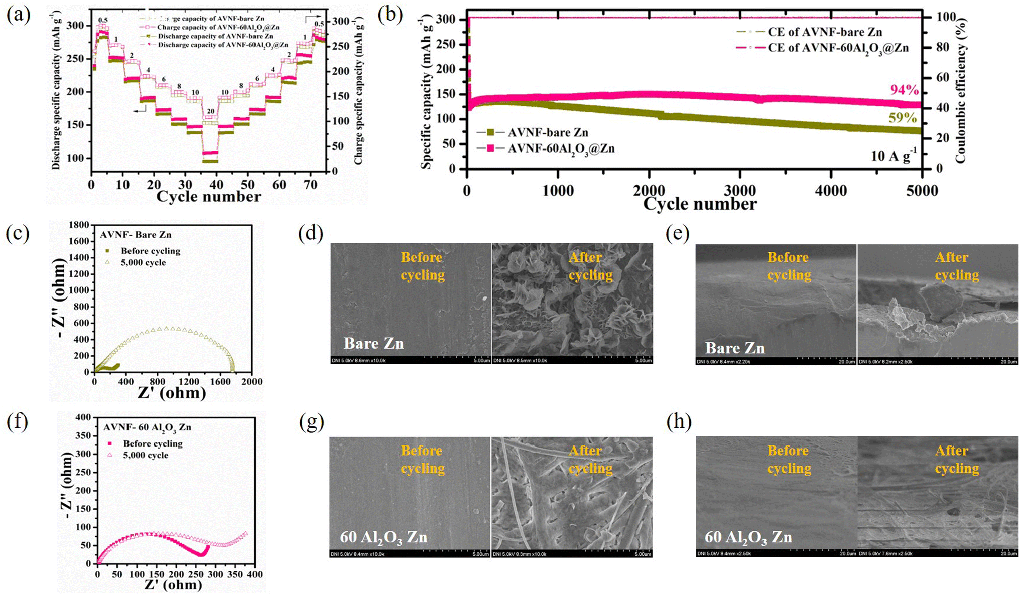 | ||
| Fig. 8 (a) Rate capability of AVNF//bare Zn and AVNF//60Al2O3@Zn. (b) Cycling performance of AVNF//bare Zn and AVNF//60Al2O3@Zn. (c) EIS measurement of AVNF//bare Zn before and after 5000 cycles. SEM images of the bare Zn surface before and after 5000 cycles: (d) top view and (e) cross-sectional view. (f) EIS measurement of AVNF//60Al2O3@Zn before and after 5000 cycles. SEM images of the 60Al2O3@Zn surface before and after 5000 cycles: (g) top view and (h) cross-sectional view. | ||
These high specific capacities were attributed to the AVNF structure. The one-dimensional structure of AVNF provided a shortened ion diffusion pathway and the interplanar distance was widened due to the ammonium ion, enabling fast ion diffusion in AVNF. The electrostatic interaction between the Zn ion and AVNF was reduced by the intercalated H2O, resulting in a high reversible specific capacity. A slight specific capacity enhancement was obtained in AVNF//60Al2O3@Zn since the charging characteristics of AVNF//60Al2O3@Zn were improved by Zn anode surface stabilization. AVNF//60Al2O3@Zn exhibited the highest specific energy density (220.7 W h kg−1) with a specific power density (379.0 W kg−1) at 0.5 A g−1. Even at a high current of 20 A g−1, AVNF//60Al2O3@Zn presented a specific energy density (54.7 W h kg−1) with a maximum specific power density of 10149.7 W kg−1. Our battery showed superior energy and power densities to previously reported ZIB, as displayed in Fig. S4.†59–66 Apart from AVNF//60Al2O3@Zn, the rate capability profiles of AVNF with 20, 40, 80 and 100Al2O3@Zn half-cells are displayed in Fig. S5(a).† The specific capacities were higher in the order of 40 > 20 > 80 > 100Al2O3@Zn, corresponding to the decreasing order of overpotential in the symmetric cell test.
Fig. 8(b) indicates the cycle stability and CE at 10 A g−1 of AVNF//bare Zn and AVNF//60Al2O3@Zn. After 5000 cycles, AVNF//60Al2O3@Zn maintained 94% of the initial specific capacity, while AVNF//bare Zn maintained only 59% of the initial specific capacity. Because the Al2O3 layer mechanically suppressed dendrite formation and prevented electrolyte decomposition, the cycle performance was significantly improved. Fig. S5(b)† shows the cycle performance of 20, 40, 80, and 100Al2O3@Zn. AVNF with 20 and 40Al2O3@Zn cells retained 66% and 82% of initial capacity, respectively, indicating a poor mechanical dendrite suppression effect due to the thin Al2O3 layer. On the other hand, 80 and 100Al2O3@Zn maintained 96% and 100% of their initial capacity, respectively. AVNF//100Al2O3@Zn showed a slight capacity increase after 5000 cycles, which indicates that sufficient cycles were required to create uniform ion diffusion. 80 and 100Al2O3@Zn exhibited better cycling performance than AVNF//60Al2O3@Zn; however, they exhibited lower specific capacity. The specific capacities of AVNF with 80 and 100Al2O3@Zn at 10 A g−1 were 135.29 mA h g−1 and 130.27 mA h g−1, respectively, which were 85% and 82% of the specific capacity of AVNF//60Al2O3@Zn.
The impedance behavior and SEM images of AVNF//bare Zn before and after 5000 cycles are shown in Fig. 8(c)–(e). After 5000 cycles, the charge transfer resistance (Rct) was significantly increased from 56.24 to 1753 Ω, suggesting a deterioration in the electrode/electrolyte interphase due to repeated electrolyte decomposition and dendrite formation. Compared to a pristine bare Zn surface, dendrite formation was clearly observed on the cycled bare Zn electrode surface. On the other hand, the change in the impedance behavior of AVNF//60Al2O3@Zn was relatively small, as shown in Fig. 8(f). This indicates that the 60Al2O3 layer suppressed the electrolyte decomposition and promoted even ion diffusion. The SEM images of Fig. 8(g) and (h) revealed mossy-like dendrite formation on the 60Al2O3@Zn surface after the cycles, which demonstrates that the surface of the 60Al2O3 layer effectively stabilized the Zn metal surface. The SEM images of pristine and 20, 40, 80, 100Al2O3@Zn are shown in Fig. S6 and S7.† Sharp dendrite flakes were clearly observed in 20 and 40Al2O3@Zn, which implied they could not mechanically suppress dendrite growth. On the other hand, 80 and 100Al2O3@Zn presented a relatively flat surface with many fewer Zn dendrite flakes.
Because of poor mechanical dendrite suppression, 20 and 40Al2O3@Zn exhibited dendrite formation on the metal surfaces. On the other hand, mossy-like dendrite formation was observed in 80 and 100Al2O3@Zn. Considering all the electrochemical results, 60Al2O3@Zn was determined to be the best thickness for improved cycling performance.
4 Conclusion
In order to achieve both high rate capability and cycle stability of ZIBs, we introduced AVNFs synthesized by a facile sonochemical method as cathode materials and Al2O3@Zn coated through the ALD technique as anode materials. The ammonium ions and H2O intercalated AVNF structure performed with high specific capacity. We found the optimal Al2O3 thickness to minimize cell polarization and form a stable ion pathway. In addition, a 9.9 nm layer of Al2O3 reduced dendrite formation on the Zn anode during charging/discharging. The rate capability of AVNF//60Al2O3@Zn indicates a high value, which is 108 mA h g−1 even at 20 A g−1, and the cell shows very high cycling stability, whose initial specific capacity is maintained at 94% after 5000 cycles at 10 A g−1. Surface stabilization of Zn by Al2O3 was confirmed by SEM images as compared with AVNF//bare Zn and AVNF//60Al2O3@Zn after 5000 cycles. Based on the results of this study, it is expected that advanced research on the active material of the cathode and surface modification of the anode with improved electrochemical performance will be possible in the future.Author contributions
Conceptualization: Sang-Hwa Lee, Se Hun Lee. Methodology: JuSang Park, Se Hun Lee, Jeeyoung Yoo, Young Joon Kim. Validation: Tae Woong Cho, Juyeon Han, Gyung Hyun Kim. Formal analysis: Sang-Hwa Lee, Se Hun Lee, Tae Woong Cho, Sungwook Mhin. Investigation: Tae Woong Cho, Juyeon Han, Sihyun Lee, Eun Jung Lee. Supervision: Sang Yoon Park, Jeeyoung Yoo, Sang-Hwa Lee, JuSang Park. Project administration: Sang Yoon Park, Young Joon Yoo. Data Curation: Eun Jung Lee, Tae Woong Cho, Gyung Hyun Kim, Sang-hwa Lee. Writing-original draft: Sang-hwa Lee, Se Hun Lee, Juyeon Han. Writing-review & editing: Sang-hwa Lee, Se Hun Lee, Jeeyoung Yoo, Sungwook Mhin, Young Joon Yoo, Sang Yoon Park.Conflicts of interest
There are no conflicts to declare.Acknowledgements
This research was supported by Nano-Material Technology Development Program through the National Research Foundation of Korea (NRF) funded by Ministry of Science and ICT (No. 2018M3A7B4070990); National Research Foundation of Korea (NRF) grant funded by the Korea Government (MSIT) (No. 2020R1A2C2103137, 2020R1F1A1076359, 2021R1A4A1031761, 2022R1C1C2011696); Technology Innovation Program funded By the Ministry of Trade, industry & Energy(Korea) (No. 20020216-K_G012002021601-10054408); Industrial Strategic Technology Development Program-ATC+ (20018007, Safe Secondary Zin Ion Battery System with long-life cycle for Personal Mobilities) funded by the Ministry of Trade, Industry & Energy (MOTIE, Korea); Ministry of Trade, Industry, and Energy (MOTIE), Korea, under the "Cooperation program for regional leading industrial complexes"; Materials, Components & Equipment Research Program funded by the Gyeonggi Province (No. AICT-018-T3).References
- B. Flamme, G. R. Garcia, M. Weil, M. Haddad, P. Phansavath, V. Rvelomana-Vidal and A. Chagnes, Green Chem., 2017, 19, 1828 RSC.
- L. Long, S. Wang, M. Xiao and Y. g Meng, J. Mater. Chem. A, 2016, 4, 10038 RSC.
- S. S. Zhang, J. Power Sources, 2006, 162, 1379 CrossRef CAS.
- G. Fang, J. Zhou, A. Pan and S. Liang, ACS Energy Lett., 2018, 3, 2480 CrossRef CAS.
- X. Zeng, J. Hao, Z. Wang, J. Mao and Z. Guo, Energy Storage Mater., 2019, 20, 410 CrossRef.
- H. Li, L. Ma, C. Han, Z. Wang, Z. Liu, Z. Tang and C. Zhi, Nano Energy, 2019, 62, 550 CrossRef CAS.
- M. Song, H. Tan, D. Chao and H. Fan, Adv. Funct. Mater., 2018, 28, 1802564 CrossRef.
- M. Winter and R. J. Brodd, Chem. Rev., 2005, 105, 1021 CrossRef CAS.
- Y. Wang and W.-Ho Zhong, ChemElectroChem, 2015, 2, 22 CrossRef CAS.
- H. Pan, Y. Shao, P. Yan, Y. Cheng, K. S. Han, Z. Nie, C. Wang, J. Yang, X. Li, P. Bhattacharya, K. T. Mueller and J. Liu, Nat. Energy, 2016, 1, 16039 CrossRef CAS.
- N. Zhang, F. Cheng, Y. Liu, Q. Zhao, K. Lei, C. Chen, X. Liu and J. Chen, J. Am. Chem. Soc., 2016, 138, 12894 CrossRef CAS PubMed.
- H. Liang, Z. Cao, F. Ming, W. Zhang, D. H. Anjum, Y. Cui, L. Cavallo and H. N. Alshareef, Nano Lett., 2019, 19, 3199 CrossRef CAS PubMed.
- F. Wang, O. Borodin, T. Gao, X. Fan, W. Sun, F. Han, A. Faraone, J. A. Dura, K. Xu and C. Wang, Nat. Mater., 2018, 17, 543 CrossRef CAS PubMed.
- D. Kundu, B. D. Adams, V. Duffort, S. H. Vajargah and L. F. Nazar, Nat. Energy, 2016, 1, 16119 CrossRef CAS.
- E. Londero and E. Schrdöer, Phys. Rev. B: Condens. Matter Mater. Phys., 2010, 82, 054116 CrossRef.
- X. Qin, X. Wang, J. Sun, Q. Lu, A. Omar and D. Mikhailova, Front. Chem. Eng., 2020, 8, 199 CrossRef PubMed.
- Y. i Li, Z. Huang, P. K. Kalambate, Y. Zhong, Z. Huang, M. Xie, Y. Shen and Y. Huang, Nano Energy, 2019, 60, 752 CrossRef CAS.
- N. Zhang, Y. Dong, M. Jia, X. Bian, Y. Wang, M. Qiu, J. Xu, Y. Liu, L. Jiao and F. Cheng, ACS Energy Lett., 2018, 3, 1366 CrossRef CAS.
- F. Wan and Z. Niu, Angew. Chem., 2019, 131, 16508 CrossRef.
- P. He, G. Zhang, X. Liao, M. Yan, X. Xu, Q. An, J. Liu and L. Mai, Adv. Energy Mater., 2018, 8, 1702463 CrossRef.
- G.-T. Zhou, X. Wang and J. C. Yu, Cryst. Growth Des., 2005, 5, 969 CrossRef CAS.
- Y.-J. Liu, J. Cowen, T. Kaplan, D. DeGroot, J. Schindler, C. Kannewurf and M. Kanatzidis, Chem. Mater., 1995, 7, 1616 CrossRef CAS.
- J. -f. Liu, X. Wang, Q. Peng and Y. Li, Adv. Mater., 2005, 17, 764 CrossRef CAS.
- H. Wang, Y. Ren, W. Wang, X. Huang, K. Huang, Y. Wang and S. Liu, J. Power Sources, 2012, 199, 315 CrossRef CAS.
- S. H. Lee, J. H. Bang, J. Kim, C. Park, M. S. Choi, A. Mirzaei, S. S. Im, H. Ahn and H. W. Kim, Sens. Actuators, B, 2021, 327, 128924 CrossRef CAS.
- S. H. Lee, C. Park, J. W. Park, S. J. Kim, S. S. Im and H. Ahn, J. Power Sources, 2019, 414, 460 CrossRef CAS.
- J. Kim, S.H. Lee, C. Park, H. S. Kim, J. H. Park, K. Y. Chung and H. Ahn, Adv. Funct. Mater., 2021, 31, 2100005 CrossRef CAS.
- T.-H. Wu, Y. Zhang, Z. D. Althouse and N. Liu, Mater. Today Nano, 2019, 6, 100032 CrossRef.
- S. Higashi, S. W. Lee, J. S. Lee, K. Takechi and Y. Cui, Nat. Commun., 2016, 7, 11801 CrossRef PubMed.
- Q. Yang, G. Liang, Y. Guo, Z. Liu, B. Yan, D. Wang, Z. Huang, X. Li, J. Fan and C. Zhi, Adv. Mater., 2019, 43, 1903778 CrossRef PubMed.
- X. G. Zhang, J. Power Sources, 2006, 163, 591 CrossRef CAS.
- D. Chao, C. Zhu, M. S. Song, P. Liang, X. Zhang, N. H. Tiep, H. Zhao, J. Wang, R. Wang, H. Zhang and H. J. Fan, Adv. Mater., 2018, 30, 1803181 CrossRef PubMed.
- D. E. Turney, J. W. Gallaway, G. G. Yadav, R. Ramirez, M. Nyce, S. Banerjee, Y.-c. Karen, C. Wiegart, J. Wang, M. J. D'Ambrose, S. Kolhekar, J. Huang and X. Wei, Chem. Mater., 2017, 29, 4819 CrossRef CAS.
- M. Cui, Y. Xiao, L. Kang, W. Du, Y. Gao, X. Sun, Y. Zhou, X. Li, H. Li, F. Jiang and C. Zhi, ACS Appl. Energy Mater., 2019, 2, 6490 CrossRef CAS.
- W. Li, K. Wang, M. Zhou, H. Zhan, S. Cheng and K. Jiang, ACS Appl. Mater. Interfaces, 2018, 10, 22059 CrossRef CAS PubMed.
- L. Kang, M. Cui, F. Jiang, Y. Gao, H. Luo, J. Liu, W. Liang and C. Zhi, Adv. Energy Mater., 2018, 8, 1801090 CrossRef.
- H. He, H. Tong, X. Song, X. Song and J. Liu, J. Mater. Chem. A, 2020, 8, 7836 RSC.
- L. dai, T. Wang, B. Jin, N. Liu, Y. Niu, W. Meng, Z. Gao, X. Wu, L. Wang and Z. He, Surf. Coat. Technol., 2021, 4277, 127813 CrossRef.
- R. Wang, Q. Wu, M. Wu, J. Zheng, J. Cui, Q. Kang, Z. Qi, J. Ma, Z. Wang and H. Liang, Nano Res., 2022, 15, 7227 CrossRef CAS.
- K. Suslick, S. Doktycz and E. Flint, Ultrasonics, 1990, 28, 280 CrossRef CAS PubMed.
- K. S. Suslick, D. A. Hammerton and R. E. Cline, J. Am. Chem. Soc., 1986, 108, 5641 CrossRef CAS.
- S. H. Lee, J. M. Koo, S. G. Oh and S. S. Im, Mater. Chem. Phys., 2017, 194, 313 CrossRef CAS.
- S. H. Lee, W. Cho, D. K. Hwang, T.K. Lee, Y. S. Kang and S. S. Im, Electrochim. Acta, 2017, 24, 607 CrossRef.
- N. Pinna, U. Wild, J. Urban and R. Schlögl, Adv. Mater., 2003, 15, 329 CrossRef CAS.
- B. Azambre, M. Hudson and O. Heintz, J. Mater. Chem., 2003, 13, 385 RSC.
- G. T. Chandrappa, P. Chithaiah, S. Ashoka and J. Livage, Inorg. Chem., 2011, 50, 7421 CrossRef CAS PubMed.
- A. Dobley, K. Ngala, S. Yang, P. Y. Zavalij and M. S. Whittingham, Chem. Mater., 2001, 13, 4382 CrossRef CAS.
- T. Ivanova and A. Harizanova, Mater. Res. Bull., 2005, 40, 411 CrossRef CAS.
- M. Najdoski, V. Koleva and A. Samet, Dalton Trans., 2014, 43, 12536 RSC.
- T. Wei, Q. Li, G. Yang and C. Wang, J. Mater. Chem. A, 2018, 6, 20402 RSC.
- S. Hong, R. M. Doughty, F. E. Osterloh and J. V. Zaikina, J. Mater. Chem. A, 2019, 7, 12303 RSC.
- J. H. Kim, Y. J. Jang, J. H. Kim, J.-W. Jang, S. H. Choi and J. S. Lee, Nanoscale, 2015, 7, 19144 RSC.
- V. Miikkulainen, M. Leskelä, M. Ritala and R. L. Puurunen, J. Appl. Phys., 2013, 113, 021301 CrossRef.
- K. H. Chen, K. N. Wood, E. Kazyak, W. S. Lepage, A. L. Davis, A. J. Sanchez and N. P. Dasgupta, J. Mater. Chem. A, 2017, 5, 11671 RSC.
- X. Liu, F. Yang, W. Xu, Y. Zheng, J. He and X. Lu, Adv. Sci., 2020, 7, 1 Search PubMed.
- K. N. Wood, E. Kazyak, A. F. Chadwick, K. H. Chen, J. G. Zhang, K. Thoronton and N. P. Dasgupta, ACS Cent. Sci., 2016, 2, 790 CrossRef CAS PubMed.
- J. H. Woo, J. J. Travis, S. M. George and S.-H. Lee, J. Electrochem. Soc., 2015, 162, A344 CrossRef CAS.
- Z. Wu, X. Zhang, L. Deng, Y. Zhang, Z. Wang, Y. Shen and G. Shao, Energy Environ. Mater., 2022, 5, 285 CrossRef CAS.
- B. Sambandam, V. Soundharrajan, S. Kim, M. H. Alfaruqi, J. Jo, S. Kim, V. Mathew, Y. K. Sun and J. Kim, J. Mater. Chem. A, 2018, 6, 3850 RSC.
- H. Qin, Z. Yang, L. Chen, X. Chen and L. Wang, J. Mater. Chem. A, 2018, 6, 23757 RSC.
- V. Soundharrajan, B. Sambandam, S. Kim, M. H. Alfaruqi, D. Y. Putro, J. Jo, S. Kim, V. Mathew, Y. K. Sun and J. Kim, Nano Lett., 2018, 18, 2402 CrossRef CAS PubMed.
- C. Shen, X. Li, N. Li, K. Xie, J. G. Wang, X. Liu and B. Wei, ACS Appl. Mater. Interfaces, 2018, 10, 25446 CrossRef CAS PubMed.
- X. Dai, F. Wan, L. Zhang, H. Cao and Z. Niu, Energy Storage Mater., 2019, 17, 143 CrossRef.
- B. Sambandam, V. Soundharrajan, S. Kim, M. H. Alfaruqi, J. Jo, S. Kim, V. Mathew, Y. K. Sun and J. Kim, J. Mater. Chem. A, 2018, 6, 15530 RSC.
- K. Lu, B. Song, Y. Zhang, H. Ma and J. Zhang, J. Mater. Chem. A, 2017, 5, 23628 RSC.
- T. Gupta, A. Kim, S. Phadke, S. Biswas, T. Luong, B. J. Hertzberg, M. Chamoun, K. Evans-Lutterodt and D. A. Steingart, J. Power Sources, 2016, 305, 22 CrossRef CAS.
Footnotes |
| † Electronic supplementary information (ESI) available. See DOI: https://doi.org/10.1039/d2nr06372g |
| ‡ These authors equally contributed to this work. |
| This journal is © The Royal Society of Chemistry 2023 |