
 Open Access Article
 This Open Access Article is licensed under a Creative Commons Attribution-Non Commercial 3.0 Unported Licence
Tuning heterogeneous ion-radiation damage by composition in NixFe1−x binary single crystals
E.
Wyszkowska
 *a,
C.
Mieszczynski
a,
Ł.
Kurpaska
a,
A.
Azarov
b,
I.
Jóźwik
a,
A.
Kosińska
a,
W.
Chromiński
ad,
R.
Diduszko
ac,
W. Y.
Huo
*a,
I.
Cieślik
a and
J.
Jagielski
ac
*a,
C.
Mieszczynski
a,
Ł.
Kurpaska
a,
A.
Azarov
b,
I.
Jóźwik
a,
A.
Kosińska
a,
W.
Chromiński
ad,
R.
Diduszko
ac,
W. Y.
Huo
*a,
I.
Cieślik
a and
J.
Jagielski
ac
aNational Centre for Nuclear Research, NOMATEN CoE MAB+, Andrzeja Soltana 7, 05-400 Otwock-Swierk, Poland. E-mail: edyta.wyszkowska@ncbj.gov.pl; wenyi.huo@ncbj.gov.pl
bCentre for Materials Science and Nanotechnology, University of Oslo, PO Box 1048 Blindern, N-0316 Oslo, Norway
cLukasiewicz Research Network – Institute of Microelectronics and Photonics, Al. Lotników 32/46, Warsaw, Poland
dWarsaw University of Technology, Faculty of Materials Science and Engineering, Wołoska 141, 02-507 Warsaw, Poland
First published on 8th February 2023
Abstract
Radiation-induced heterogeneous damage is the single largest source of failures seen in structural components in nuclear power reactors. Single crystal materials without grain boundaries, show considerable promise for overcoming this problem. In this work, such heterogeneous damage was further overcome in NixFe1−x single crystal alloys via a simple strategy of fine-tuning the composition. [001] NixFe1−x (x = 0, 0.38 and 0.62 at%) single crystals prepared using the Bridgman method were irradiated over a wide fluence range (4 × 10¹³ to 4 × 10¹⁵ ions per cm2). The irradiation-induced defect evolution was studied using Rutherford backscattering/channeling spectrometry, Monte Carlo simulations, transmission electron microscopy and nanoindentation. The results indicate an increased radiation tolerance of Ni0.38Fe0.62 compared to pure Ni and Ni0.62Fe0.38. The structural analysis performed by transmission electron microscopy revealed that defects tend to agglomerate at one place in Ni and Ni0.62Fe0.38, while in Ni0.38Fe0.62 no defect accumulation zone (characteristic damage peak) has been captured either at low or high fluence. Moreover, we found that the hardness change with the increase of Fe content is due to different arrangements of Fe atoms in the crystal structure, which influences the obtained mechanical properties of NixFe1−x in the pristine state and after ion implantation.
1. Introduction
The growing interest in the development of the nuclear industry worldwide is, among many others, a driving force to explore and investigate new groups of radiation resistant materials.1–4 Materials to be used as components of future fission and fusion reactors should be carefully selected due to harsh operational conditions.5–9 Therefore, while investigating these new groups of materials for such applications, special attention should be given to the high radiation tolerance, high thermal and phase stabilities, and elevated mechanical properties.3,10 Several papers and reports have described essential materials suggested for advanced fission reactors, especially Generation IV reactors.1,5,8,11–14 However, despite broad studies and advancements, multiple phenomena still require thorough investigation and explanation. Such phenomena include, among others the swelling effect,7,15–18 embrittlement,2,5,7 or defect agglomeration zones, all induced by ion irradiation. As noted above, structural materials for next-generation fission reactors are prone to damage under irradiation. In particular, the formation of large vacancy clusters significantly deteriorates the performance of materials, as migrating and accumulating vacancies may lead to hardening and void swelling.7 Therefore, controlling vacancy cluster migration and growth is crucial in selecting new advanced structural materials for nuclear applications.1–3 Modifying the compositional complexity of alloys has been considered a way to resolve the aforementioned challenges. Ni and NixFe1−x single crystal alloys are promising materials due to their extraordinary mechanical properties and high radiation tolerance.2 Unlike novel, high entropy alloys or oxide-dispersion-strengthened (ODS) steels which face material processing challenges and show structural instability at elevated temperatures,2 single crystal alloys benefit from their simple structure.1,3 Due to the lack of grain boundaries within a single crystal, they are characterized by unique mechanical properties. Moreover, the possibility of modeling the development of defects using various techniques (e.g., ion channeling simulations, molecular dynamic simulations, etc.) is one of many advantages of choosing single crystals.1–3 Recent studies have shown that single-phase concentrated (binary and ternary) solid solution alloys exhibit outstanding mechanical and irradiation resistance properties in Ni-based systems.1–3,19,20 Their properties rely on a well-ordered structure. Moreover, the processes, such as defect creation induced during ion irradiation or defect migration, can be easier to capture and understand than in amorphous materials.It is common practice to manipulate chemical composition to achieve the desired material properties.21 For this reason, we developed a novel chemical composition of the material and compared its functional properties with its pure counterparts and literature studies. In our research, pure Ni and NixFe1−x single crystal fcc alloys (with 0.38 and 0.62 at% of Fe element) were subjected to ion irradiation. Specimens for structural and nanomechanical investigations were irradiated with 1.5 MeV 58Ni+ ions at room temperature with fluences of 4 × 10¹³, 2 × 10¹⁴, 5 × 10¹⁴, and 4 × 10¹⁵ ions per cm2. Afterward, the Rutherford backscattering spectrometry (RBS/C ion channeling) technique was used for the qualitative and quantitative evaluation of radiation damage. The analysis was performed for fluences of 4 × 10¹³, 2 × 10¹⁴, 1 × 10¹⁵, and 2 × 10¹⁵ ions per cm2. In addition, the RBS/C spectra were fitted using a Monte Carlo (MC) simulation, which allowed us to determine the number of defects and their distribution within the single crystals. The RBS/C technique enabled us to identify the level of radiation damage for the considered compositions in various fluences. The obtained results are consistent with the Monte Carlo simulations. Subsequently, to confirm these findings, additional investigations using transmission electron microscopy (TEM) have been performed to verify the types of radiation defects and their concentrations as a function of ion fluences. The results from both experiments provided comprehensive insight into the structural changes of the studied material.
2. Experiment and methods
2.1. Single crystal production and sample preparation
All single crystals considered in this work have been produced at the National Centre for Nuclear Research (NCBJ) in Otwock-Świerk, Poland.22 Specimens were created using the vertical temperature gradient method (the Bridgman method23). In this method, Ni and Fe metals characterized by high melting point temperatures were melted in an alundum crucible in which the heating element was a molybdenum wire. The crystallization process occurs due to the slow lowering of the crucible (from 1 to 2 cm per hour). Melting and crystallization took place under argon's inert gas protective atmosphere. The typical production time for one single crystal was 30 hours.Samples for an ion irradiation experiment were cut along the [001] direction, grounded, and polished according to standard procedures. Mechanical grinding was performed on abrasive papers with grit sizes from 400 to 4000. In the next step, the samples were polished to a mirror-like surface finish using diamond pastes with grain sizes of 6 µm, 3 µm, and 0.5 µm. Subsequently, the samples were polished using electropolishing equipment (Struers LectroPol-5) with a mixture of 60% electrolytic perchloric acid and water to reduce stresses after mechanical polishing. The polishing time was set to 60 s, and the electric potential was 30 V.
2.2. Ion irradiation
Irradiation was carried out at room temperature with 1.5 MeV 58Ni+ ions using a 1 MV tandem accelerator (National Electrostatics Corporation, model 3SDH-2). The ion fluences ranged from 4 × 10¹³ ions per cm2 to 4 × 10¹⁵ ions per cm2. All implantations were performed at room temperature at 7 degrees off the normal direction to avoid channeling. The mean projected range of Ni ions in the NixFe1−x single crystal alloys was estimated using full cascade mode in the SRIM (Stopping Ion Range in Matter) program.242.3. RBS/C measurements and simulations
After implantation, the samples were measured by Rutherford backscattering spectrometry in channeling mode (RBS/C) using 1.6 MeV He+ ions in the [001] direction and backscattered into a detector placed at 165° relative to the incident beam direction.The RBS/C spectra of pure Ni and NixFe1−x alloys implanted with different fluences were simulated using the Monte Carlo (MC) McChasy code developed at the NCBJ.25,26 A detailed description of the simulation procedures and the model of extended defects (Ext. Def.) used can be found in ref. 25–27. The experimentally obtained spectra combined with the simulated spectra are shown in Fig. 2 and 3. The solid lines corresponding to the spectra in an aligned [001] direction were obtained using MC simulations. The mean projected ranges of ions and induced defect distributions for Ni ions shown in Fig. 2 and 3 were estimated by SRIM simulations.24,28,29 The corresponding displacement per atom (dpa) profiles were predicted by the SRIM code under a displacement energy threshold of 40 eV for all elements using the full cascade mode. The SRIM-estimated damage peak is located at a depth of approximately 400 nm.
In Fig. 1 the damage profiles of Ni (Fig. 1A), Ni0.62Fe0.38 (Fig. 1B), and Ni0.38Fe0.62 (Fig. 1C) irradiated with 1.5 MeV of Ni+ at fluences from 4 × 10¹³ ions per cm2 to 4 × 10¹⁵ ions per cm2 are presented. The ion distribution was estimated from the RANGE.txt file. The corresponding dpa profiles were calculated using two files, VACANCY.txt and NOVAC.txt, under an assumed displacement energy threshold of 40 eV for all elements. The dpa profile is the sum of the vacancy concentrations using the column of “Knock-Ons” for Ni ions and the columns of “Vacancies” from target elements (the sum of Ni vacancies and Fe vacancies in the case of NixFe1−x) in VACANCY.txt, together with the replacement collisions in NOVAC.txt.30 Ion-induced damage in monoatomic and multi-elemental targets was predicted using full-cascade simulations.25,29,31,32
 | ||
| Fig. 1 Damage profiles of (A) Ni, (B) Ni0.62Fe0.38 and (C) Ni0.38Fe0.62 irradiated with 1.5 MeV of Ni+ at fluences of 4 × 10¹³, 2 × 10⁴, 5 × 10¹⁴, 1 × 10¹⁵, 2 × 10¹⁵ and 4 × 10¹⁵ ions per cm2. | ||
2.4. Nanoindentation
Nanoindentation was performed utilizing a NanoTest Vantage system from Micro Materials Ltd. A Synton-MDP diamond Berkovich-shaped indenter was used in this study. Tests were conducted in multiple load cycles with increasing load from 0.5 mN up to 10 mN (in a total of ten cycles) using the load-controlled method. At least 16 indentations were made at each load with 50 µm spacing between the indents. Before starting the indentation test, a diamond area function (DAF) of the indenter tip was calculated. Calibration was performed using a fused silica material over a wide load range to assess a reliable indenter shape for a given indentation depth. The described method allows hardness extraction from indentation load-displacement curves during one cycle of loading and unloading.33 Once the contact area is determined, the hardness is estimated from H = Pmax/A, where Pmax represents the maximum load, and A is the projected contact area at a specific peak load.2.5. TEM defect characterization
TEM samples were prepared using the lift-out procedure and employing a focused ion beam system (Ga+) installed in a Helios 5 UX (ThermoFisher Scientific) microscope. This allowed us to obtain thin lamellas with electron transparency. Final thinning of the lamellae was performed with 5 keV Ga+ ions followed by a 2 keV Ga+ gentle polishing. TEM observations were performed with a JEOL JEM1200EX II microscope. Observations were carried out under a diffraction vector of g = 200 for bright-field imaging. Weak beam dark field g–3 g imaging was performed for the same diffraction vector. The two-beam convergent beam electron diffraction technique was used to determine the foil thickness (for dislocation density statistics).343. Results
3.1. RBS/C analysis and simulations
RBS/C analysis is an excellent tool for understanding the interaction between the injected ions and the structure in the surface region, which is usually less than 1 µm thick.35,36 The RBS/C spectra were fitted using McChasy, a Monte Carlo simulation package allowing the quantitative analysis of channeling spectra. According to the procedures developed in our group,25,26 the current investigations were performed mainly using the extended defect representation. The other parameters and simulation conditions (geometry etc.) were chosen carefully to match the experimental data. It is worth mentioning that in the channeling mode, ion beam analysis reveals the crystal structure and therefore can be used an alternative tool for crystallography, which is the domain of X-ray and neutron diffraction analysis. Using MeV He ions with wavelengths of 10−12 cm, the lattice is not viewed as a diffraction grating but rather as an actual crystal of rows and sheets of atoms that collimate and steer the beam. On the scale of lattice spacing, the MeV ion is a point probe weaving through the channels provided by the rows and planes of atoms.35Fig. 2 shows the ion channeling spectra for pure Ni, Ni0.62Fe0.38, and Ni0.38Fe0.62 subjected to ion irradiation. One can observe that the random spectra attributed to the amorphous materials are considerably higher than the other spectra. In high-quality undamaged crystals, the backscattering yield is low (presented as the virgin level in Fig. 2A–C).2,35 At the same time, fluence-dependent ion channeling spectra usually rise as a function of damage. In other words, once the host atoms are displaced from their lattice sites, they can interact with the channeled beam, and an increase in the scattering yield is observed.
 | ||
| Fig. 2 Ion channeling spectra of (A) Ni, (B) Ni0.62Fe0.38, and (C) Ni0.38Fe0.62 single crystals irradiated with fluences from 4 × 10¹³ to 2 × 10¹⁵ ions per cm2. Solid lines represent fits obtained using MC simulations. Virgin and random spectra are included as references. | ||
The most significant damage propagation (the highest backscattering yield) was observed for pure Ni, while the backscattering yield of Ni with 62 at% of Fe is the lowest (Fig. 2A–C) at each analyzed fluence. This effect suggests better radiation tolerance of the material with the addition of Fe. The addition of 38 at% Fe triggers an increase in the radiation resistance compared to pure Ni. A drastic yield build-up for the low fluence of 4 × 10¹³ ions per cm2 (approximately 0.1 dpa) is observed in Ni, while for the other compositions, the backscattering yield for this fluence is considerably lower. As the irradiation fluence increases up to 1 × 10¹⁵ and 2 × 10¹⁵ ions per cm2 (damage levels of approximately 3 and 6 dpa, respectively), a visible decrease in the yield for the pure Ni specimen can be noticed. The variation of the backscattering yield depends strongly on the general lattice distortion after the interaction of He ions with the lattice of the implanted material. Therefore, we observed an increased backscattering yield with increasing lattice distortion. Usually, in metals, most of the defects are mainly extended defects, e.g., dislocations or stacking faults, which lead to the dechanneling of incident He ions. Furthermore, in metals, we usually see the evolution of smaller defects occurring below the sample surface into larger, more complex defects at higher depths, as shown in the TEM images (Fig. 7A and B). Therefore, it can be assumed that lattice distortion could be related to the defect size and density change since smaller defects cause smaller lattice distortion than complex defects (defect clusters and dislocation), hence the backscattering yield changes. In pure Ni, a saturation dose has been obtained at a fluence of 2 × 10¹⁴ ions per cm2. The saturation and a small decrease in the channeling yield may occur because the defect structure becomes more organized at high fluence, as reported here.21 For example, point defects are transformed into more complex ones, such as dislocation loops, or small dislocation loops are changed into larger defect clusters that release strain induced by ion irradiation. Therefore, we observed a decrease in the backscattering yield.
Moreover, one can notice that different compositions reach saturation at different fluences. This means that the defect evolution is delayed by adding more Fe to Ni. This is related to both defect generation and defect growth. Usually, at higher irradiation fluence where more Ni ions are injected into the sample (causing a significant lattice distortion after the interaction of injected He ions), the generation of new defects and a transformation from smaller to larger defects may occur. This transformation may also lead to stress release, affecting the backscattering yield. Moreover, adding Fe may effectively influence the energy transport during ion irradiation through electrons on defect formation and distribution. Moreover, if the curves overlap like in Fig. 2B, we are most likely dealing with similar defect sizes and similar densities. Ni ions cause a significant lattice distortion at higher irradiation fluence, generating new defects and transforming from smaller to larger defects. This transformation may also lead to stress release, which further affects the backscattering yield.
Fig. 3A–D show the different materials’ responses to the ion fluences depending on the chemical composition tested. For low fluence irradiation such as 4 × 10¹³ ions per cm2 (equivalent to 0.1 dpa), an increase in the backscattering yield for pure Ni is observed compared to other compositions. For Ni0.62Fe0.38, the curves overlap, while in the case of Ni0.38Fe0.62, the yield remains the lowest. As the fluence increases to 2 × 10¹⁴ ions per cm2 (damage level of approximately 0.5 dpa), a gradual decrease in the backscattering yield is observed with an increase in the Fe content. In turn, for pure Ni we observed damage saturation starting at this fluence. This trend may suggest better radiation resistance and material stability than pure Ni and Ni with a low Fe content. Somewhat miscellaneous behavior has been recorded for a higher dose of 1 × 10¹⁵ ions per cm2 (approximately 3 dpa), where up to a depth of ∼250 nm, the spectra of all materials overlap, and one may even observe an inverted intensity region. There might be two reasons for this: first, this can be related to defect migration (a damage peak for these materials is approximately 400 nm), but they can concentrate at different depths;2,37 second, the defects began to saturate at this dose. In most metallic materials, the fastest increase in the degradation level occurs in the low fluence regime, usually up to 0.5 dpa. With a higher irradiation dose, damage begins to saturate depending on the composition, which means that the damage propagation (growth) stabilizes. In Fig. 3C and D, we already start to see a decrease in the backscattering yield in pure Ni, but still, we observed the lowest yield for Ni0.38Fe0.62 – which means that Ni0.38Fe0.62 still has room for damage increase. For a better understanding of this effect, in Table 1, we noted how each composition's maximum yield value (collected at 400 nm depth as the maximum damage peak) changes with irradiation fluence.
 | ||
| Fig. 3 Recorded ion channeling spectra of Ni, Ni0.62Fe0.38 and Ni0.38Fe0.62. Specimens were irradiated with 1.5 MeV of Ni+ at fluences of (A) 4 × 10¹³, (B) 2 × 10¹⁴, (C) 1 × 10¹⁵ and (D) 2 × 10¹⁵ ions per cm2. The intensities of the spectra were normalized to the highest Ni-random spectrum. | ||
| Fluence/material | Ni | Ni0.62Fe0.38 | Ni0.38Fe0.62 |
|---|---|---|---|
| 4 × 10¹³ | 2193 | 1088 | 877 |
| 2 × 10¹⁴ | 3085 | 2359 | 1984 |
| 1 × 10¹⁵ | 2707 | 2511 | 2321 |
| 2 × 10¹⁵ | 2561 | 2388 | 2331 |
For Ni0.62Fe0.38, the backscattering yield constantly increases up to a fluence of 1 × 10¹⁵ ions per cm2 and then decreases at 2 × 10¹⁵ ions per cm2. In contrast, the backscattering yield in Ni0.38Fe0.62 is lower than that in Ni0.62Fe0.38 and increases gradually with fluence, which means that Ni0.38Fe0.62 is the most resistant among the studied compositions. Damage reaches saturation in Ni at a fluence of 2 × 10¹⁴ ions per cm2, while saturation in Ni0.62Fe0.38 occurs above at 2 × 10¹⁵ ions per cm2 and most probably for Ni0.38Fe0.62 saturation begins above 2 × 10¹⁵ ions per cm2. The best confirmation of this statement could be the TEM images presented in Fig. 8 where the damage level decreases as the Fe content increase at low and high fluences. Moreover, we suppose that the better radiation tolerance with increasing Fe content is related to the physical nature of the iron atomic nucleus in its excited state compared to pure Ni. An iron atomic nucleus is more stable because it possesses only one orbital with unpaired electrons, while Ni has three. This means that it is more vulnerable to electron movements and, thus, defect generation and mobility.
Finally, one must remember that many components used in a nuclear reactor operate only up to the time until they receive multiple dpa damage. After this time, they are replaced or as in the case of reactor pressure vessel RPV steel the whole unit is shut down. For this reason, it is of utmost importance to understand radiation damage build-up early in the defect accumulation stage.
3.2. Irradiation-induced hardening
The mechanical properties of NixFe1−x single crystal alloys have been evaluated using the nanoindentation technique. Pure Ni and Ni with different amounts of Fe (0, 12, 23, 38, and 62 at%) in a pristine state were first investigated.In Fig. 4 the hardness results as a function of Fe content are presented. From the pure nickel structure (0 at% Fe addition) to 38 at% of Fe, a gradual increase in hardness up to ∼3 GPa was recorded. At 62 at% Fe, a substantial decrease in hardness to 2.46 GPa has been recorded. One of the possible reasons for the hardness change with increasing Fe concentration during nanoindentation, as reported by Kurpaska et al.,38 can be associated with extended distributions of the formation and migration energies of vacancies and interstitials by alloying Fe with Ni. This may suggest that dislocation generation and propagation in pure Ni is easier than in NixFe1−x. They also explained that the combination of differences in the dislocation nucleation mechanisms during indentation and defect sizes might lead to a hardness increase in the NixFe1−x samples with respect to pure Ni data. The mechanism of the formation of tetrahedral stacking faults from prismatic dislocation loops (PDL) in all the studied NixFe1−x samples was also visible. A decreased mobility of PDLs and a decreased size of dislocation loops with increasing Fe content have also been noticed. Therefore, it can be assumed that the main strengthening factors are associated with gradual dislocation diffusion, reduced defect sizes, and the nucleation of tetrahedral stacking faults.38 Another possible reason for the hardness change over the various Fe compositions could be associated with a phase change of single crystals according to the phase diagram reported in ref. 39. Based on this diagram, we can assume that in a range of 10–29 at% of Fe, we are dealing with the FeNi3 (L12) phase. Next, between 29 and 47 at% of Fe, the FeNi (L10) + FeNi3 (L12) phase occurs. This is a mixture of L10 and L12 structures where the Fe atoms occupy different positions in a crystal structure. Later, we can observe the presence of the FeNi (L10) phase in a range between 48 and 54 at% of Fe. Finally, between 54 and 73 at% of Fe, we probably have a combination of the Fe3Ni (L12) + FeNi (L10) phases. The different arrangements of Fe atoms in a crystal structure may influence the hardness performance with increasing Fe content. However, more structural data are needed to prove the presence of these phases in the reported compositions.
 | ||
| Fig. 4 Nanoindentation hardness of the non-irradiated fcc Ni and NixFe1−x single crystal alloys as a function of Fe content. | ||
It is known that nanoindentation is an exquisitely important technique that helps to evaluate the phenomenon of radiation hardening in materials modified by ions to several hundred nanometers.40 A series of multicycle indentations of the irradiated Ni and NixFe1−x alloys were performed to understand the mechanical behavior after ion irradiation. In Fig. 5A, the hardness as a function of irradiation fluence is presented for pure Ni and Ni with 38 and 62 at% Fe. It can be observed that the hardness growth with increasing ion fluence is visible for all of the tested materials, and this trend can be divided into two regimes. At first, a very rapid increase in hardness at a fluence of 4 × 10¹³ ions per cm2 (approximately 0.1 dpa) is recorded. Afterward, the hardness change slows down at a level of 5 × 10¹⁴ ions per cm2 (approximately 1.5 dpa). However, the trend remained. In Fig. 5B, the hardness difference based on the equation: ΔH = Hirradiated − Hpristine has been plotted. One can see that the most significant hardness change is visible in pure Ni, followed by Ni0.62Fe0.38 and then Ni0.38Fe0.62. The possible reason for that is the addition of Fe into the system, which slows down the aggregation of the interstitial-type dislocation loops, as observed in MD simulations.38 This ultimately increases the radiation resistance of the material. Moreover, the disordered electronic structure essentially reduces the electron mean free path, so the effectiveness of the energy dissipation of a complex system decreases. This is visible in the case of radiation damage build-up. As we mentioned above, another reason for the different radiation responses of NixFe1−x could also be related to the different arrangements of Fe atoms in the crystal structure. Based on the phase diagram,39 we can assume that in a range of 29–47 at% of Fe, we deal with the FeNi (L10) + FeNi3 (L12) phase combination while for 54–73 at% of Fe, we probably have a combination of Fe3Ni (L12) + FeNi (L10) phases. The different arrangements of Fe atoms in a crystal structure may influence an irradiation-induced hardening mechanism in NixFe1−x. This hypothesis will be verified in the future.
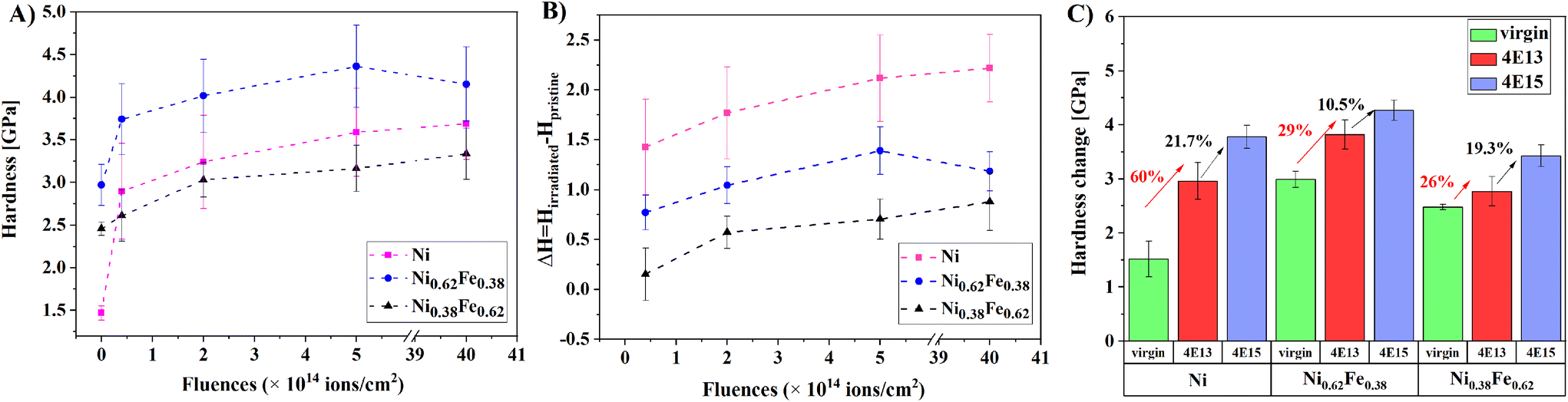 | ||
| Fig. 5 (A) Nanoindentation hardness of fcc Ni, Ni0.62Fe0.38, and Ni0.38Fe0.62 single crystal alloys as a function of irradiation fluence, (B) hardness change according to the equation ΔH = Hirradiated − Hpristine and (C) comparison of hardness changes for the pristine and irradiated samples of Ni, Ni0.62Fe0.38 and Ni0.38Fe0.62 between two fluences: 4 × 10¹³ and 4 × 10¹⁵ ions per cm2. | ||
In conclusion, the recorded data suggest that the Ni single crystal is the most sensitive material to ion irradiation. In comparison with the pristine sample in Fig. 5C, an increase in the hardness in pure Ni (for the highest fluence of 4 × 10¹⁵ ions per cm2) is approximately 60%. However, the hardness increase between the lowest and the highest dose was only ∼21.7%. As the addition of Fe increases up to 62 at%, the irradiation-induced hardening phenomenon is the smallest among the studied samples, at approximately 26%. Then, the hardness increases by 19.3% between the samples treated with the lowest and highest doses. To sum up, adding Fe to the Ni system effectively leads to an increase in radiation resistance, showing a lower level and an increase of radiation hardening.
4. Discussion
In contrast to numerous studies on the radiation resistance of fcc NixFe1−x single crystals,1–3 in this article, we focused not only on the quantitative and qualitative analysis of damage: ∼0.12, ∼0.63, ∼3.16, and ∼6.3 dpa, but also on connecting the microstructure of the material with a recorded mechanical (hardness) change. This comparison was made for damage levels of ∼0.12, ∼0.63, ∼1.58, and ∼12 dpa of new chemical compositions of fcc-type Ni0.62Fe0.38 and Ni0.38Fe0.62 single crystal alloys (recorded results were compared with pure Ni manufactured in the same way as studied monocrystals). The influence of Fe addition has been deeply studied and compared with the literature data, which revealed several interesting insights. Notably, both nanomechanical investigation and the obtained RBS/C spectra allowed us to obtain quantitative information about the radiation resistance response of the Ni, Ni0.62Fe0.38, and Ni0.38Fe0.62 compositions.The shape of the spectra reveals a continuous increase in the backscattering yield. This confirms our previous investigations25 that the backscattering is mainly due to the dechanneling of the analyzing beam and not due to a direct backscattering process, which is related to the occurrence of mainly extensive defects in the structure. It is worth mentioning that point defects can directly scatter a particle beyond the critical angle by a single collision. In contrast to localized point defects, dislocations provide an example of an extended defect in which the distortion around the defect causes dechanneling.32 This is further confirmed by structural analysis in the following discussion. The dechanneling level of aligned spectra increases as a function of irradiation fluence, following the damage induced inside the investigated material. This is conspicuous, as a continuous increase in the yield mainly proves the presence of complex defects. In turn, Jin et al.2 recorded spectra with a “knee point”, which confirms the presence of both simple and complex defects in the structure.
In Fig. 6, the damage distribution profiles of Ni (Fig. 6A), Ni0.62Fe0.38 (Fig. 6B), and Ni0.38Fe0.62 (Fig. 6C) obtained from the MC simulations are shown. The presented histograms demonstrate the quantitative values of the extensive defect concentration, leading to the dechanneling of the beam that was used to obtain the best fits of the simulation curves to the experimentally obtained data. Moreover, the depths of simulated defect distributions are close to the SRIM predicted damage profiles (vacancies and ion distributions are also plotted with the damage distribution profiles in Fig. 6A–C). In the case of pure Ni, the damage saturates at a fluence of 2 × 10¹⁴ ions per cm2 (∼0.63 dpa), and the depth of defect penetration at the maximum peak shifts to the left side. The damage accumulation peak was observed at ∼250 nm for 3.16 dpa and at 300 nm for 6.3 dpa. The defect concentration and distribution seem to look different for the Ni0.62Fe0.38 specimen. At 0.1 dpa, damage starts to accumulate at a depth of 250 nm. For the 0.59 and 2.96 dpa levels, one can observe defect accumulation at a depth of 300 nm, and finally, for the 5.9 dpa level, the damage peak moves further into the material to 380 nm depth. In the case of Ni0.38Fe0.62, the smallest increase in the number of defects to other compositions has been observed. Moreover, the number of defects in Ni0.38Fe0.62 is about twice as small as that in pure Ni. Importantly, defect accumulation at various depths may suggest the defect type and migration ability changes. It is worth noting that in fcc NixFe1−x alloys, interstitial-type defects could be dumbbell interstitials, as reported in ref. 24, 41–43. These defects are made of the split pairs of atoms centered around one atomic position and could bend the crystal lattice locally. When aligned with the ion beam, it may lead to dechanneling of the He+ ions (instead of direct scattering). A similar effect can be observed near dislocation loops.25,41–43
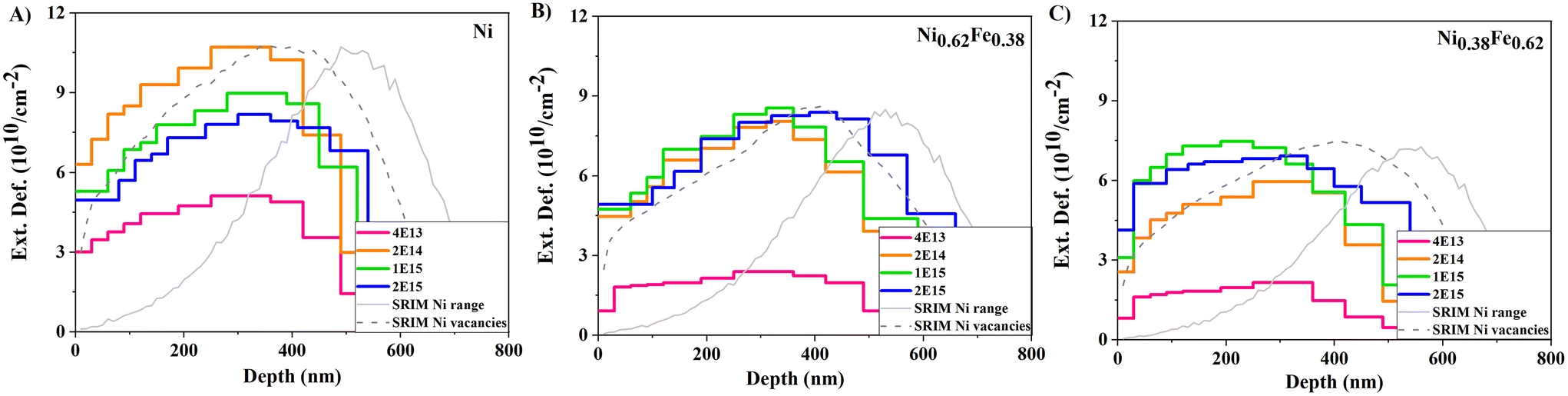 | ||
| Fig. 6 Damage distribution profiles of (A) Ni, (B) Ni0.62Fe0.38 and (C) Ni0.38Fe0.62 obtained from the MC simulations performed for experimentally obtained RBS/C spectra. Normalized to the maximal value of Ext. Def., SRIM predicted profiles of vacancies and ion ranges are plotted in a.u. Total vacancies are used to calculate fluence-related dpa values. | ||
TEM analysis was performed to confirm the conclusions related to defect migration and their type drawn from the experimental results (nanoindentation, RBS/C) and MC simulations. Since ion irradiation is a depth-dependent phenomenon, microstructural evaluation of the damage distribution below the sample surface induced by ion irradiation is crucial. In Fig. 7, cross-sectional TEM images of the three compositions (Ni, Ni0.62Fe0.38, and Ni0.38Fe0.62) irradiated with two fluences of 4 × 10¹³ ions per cm2 (Fig. 7A) and 4 × 10¹⁵ ions per cm2 (Fig. 7B) are presented. Black defect clusters were observed from the sample surface to the extended depth, migrating much further than SRIM calculations predicted for the highest fluence. For the low irradiation fluence in the case of the pure Ni specimen, large defect clusters are distributed away from the surface and start accumulating from 220 to ∼550 nm depth. In Ni0.62Fe0.38, we observed that defects tend to concentrate mainly from 250 nm up to 400 nm. Furthermore, unlike Ni and Ni0.38Fe0.62, disparate types of defects have been observed in Ni0.62Fe0.38. One can see mainly longitudinal lines (edge dislocations) and small defect clusters, whereas in Ni and Ni0.38Fe0.62, we observed defect clusters in the form of SFTs and dislocation loops. In the case of Ni0.38Fe0.62, the black defect clusters are visible and (almost) evenly distributed from the sample surface to the greater depths of the sample, where TEM analysis was performed. The defect range in all the three compositions aligns with the SRIM estimations. However, the damage peak range shifts towards the surface when increasing the iron content up to 38 at%. For the highest fluence in the case of pure Ni, the defect clusters far exceeded the SRIM predicted depth (including the maximum defect range estimated at 800 nm), reaching 1000 nm of depth. Interestingly, we observed a concentration of defects phenomenon at high irradiation fluence, similar to Ni0.62Fe0.38 at low fluence.
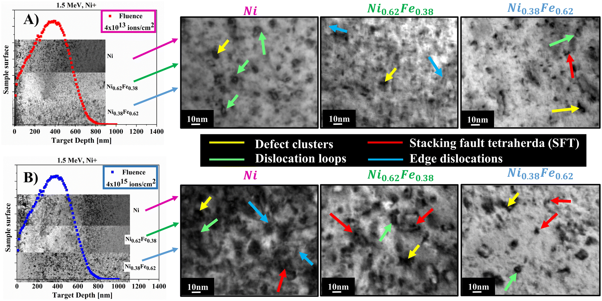 | ||
| Fig. 7 Cross-sectional TEM images of the Ni, Ni0.62Fe0.38, and Ni0.38Fe0.62 irradiated with various fluences (A) 4 × 10¹³ ions per cm2 and (B) 4 × 10¹⁵ ions per cm2 compared with SRIM calculations. In the bright-field images located on the right side, some typical defects like SFTs (marked with red arrows), dislocation loops (marked with green arrows), edge dislocations (marked with blue arrows), and defect clusters (marked with yellow arrows) have been indicated. | ||
With increasing Fe addition, the defect range decreases (Fig. 7B) for Ni0.62Fe0.38, reaching 800 nm. However, the defects aggregate in one place at around 700 nm. The reason why a damage peak shift was observed in NixFe1−x compared to Ni is because ion irradiation causes high mechanical stress, where the ions may propagate toward the bulk of the material. These stresses may drive the defects to migrate either toward the surface or further in the material bulk. As a result, we observed defect migration with an increased ion fluence as they generate a higher stress gradient due to the high amount of Ni ions implanted into the sample. The highest stress gradient is located at the center of the implanted layer (in our case, according to SRIM simulations, the damage peak was located at a depth of 400 nm). Moreover, the migration mechanism could result from a combination of processes such as defect recombination, production, cluster formation, etc. as reported in ref. 21. In this study, we observed that Fe addition could influence energy transport during ion irradiation through electrons on defect formation and distribution. Therefore, a damage peak in NixFe1−x is slightly shifted because Fe suppresses damage and stress induced by ion irradiation.
Interestingly, in the case of Ni0.38Fe0.62, both for high and low fluences, we observed an even distribution of defects from the surface towards the material bulk (without a clear zone of defect accumulation). This phenomenon may undoubtedly suppress strain localization when the material is being deformed. In the case of other compositions, where the area of defect accumulation is visible, material delamination or cracking in this region may occur.
TEM bright-field (BF) micrographs of the irradiated samples are shown in Fig. 7A and B. Most defects visible for all the compositions are black clusters, dislocation loops, edge dislocations, and vacancy-type stacking fault tetrahedra (SFT). The BF images show that black dot defects agglomerate into larger dislocation loops and are further transformed into dislocation networks. This is in line with the RBS channeling spectra in which we observed a decreasing backscattering yield for different fluences related to the reduction of lattice strain.
From the cross-sectional TEM images, several phenomena can be observed. It is clear that with increasing irradiation fluence, the range of defect distribution also increases and significantly exceeds the SRIM predicted range, which indicates that the defect migration mechanism changed due to a high level of mechanical stress induced by ion irradiation. As a result, we observed defect migration towards the material bulk with an increased ion fluence because more Ni ions are implanted into the sample. Moreover, the migration mechanism may be a result of combination processes like defect recombination, production, cluster formation, etc. which are especially visible in the high fluence regime. Second, we observed that the addition of iron appreciably affects the distribution of defects in the material. It effectively stops the migration of defects. A similar behavior has also been reported in ref. 2. Moreover, this mechanism was explained as vacancies preferring migration through Fe atoms and interstitial migration through Ni atoms.20 It was also reported that, in NixFe1−x binary systems, all sinks concentrate more Ni atoms, which influences the further interaction of mobile defects with voids and dislocations. Therefore, an increase in the void size and an increase of dislocations are observed.20
Usually, the microstructural study of an irradiated alloy consists of three stages.44 In a low ion irradiation regime (≤1 dpa), visible black dot defects could appear, and their density and average size increased with ion fluence. Meanwhile, the black dot defects also developed into larger ones, but their density decreased. Dislocation loops are formed in a higher ion irradiation regime (>1 dpa) and grow into larger loops. With increasing irradiation dose, the loop diameter increases, and they may coalesce with each other to form larger dislocation networks.44,45
In the case of Ni and NixFe1−x single crystals (Ni0.62Fe0.38 and Ni0.38Fe0.62), slightly different dependencies related to the amount of Fe element were observed. In Fig. 8, TEM images of the irradiated Ni, Ni0.62Fe0.38, and Ni0.38Fe0.62 with fluences of 4 × 10¹³ ions per cm2 and 4 × 10¹⁵ ions per cm2 are presented. All the images were taken from the peak damaged regions. Mostly large defect clusters and dislocation loops are observed for the low irradiation fluence in pure Ni. As the Fe content increases up to 38%, dislocation lines and vacancy type single stacking fault tetrahedra (SFT) with a size of a few nanometers become visible. In Ni0.38Fe0.62, small defect clusters and SFT defects are primarily observed. Moreover, an evident change in the defect size is visible with the addition of iron content. A calculation of the defect size based on the TEM images was used to confirm these findings. The analyses proved that the defect size decreases in alloys with a higher Fe content (Fig. 9A), both at low and high fluence.
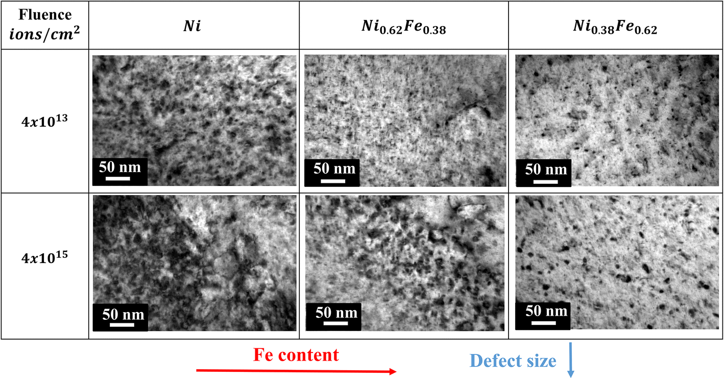 | ||
| Fig. 8 TEM images of Ni, Ni0.62Fe0.38, and Ni0.38Fe0.62 irradiated with fluences of 4 × 10¹³ ions per cm2 and 4 × 10¹⁵ ions per cm2. | ||
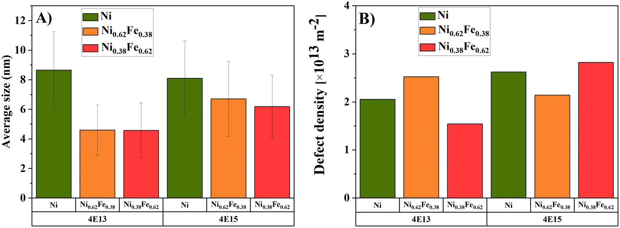 | ||
| Fig. 9 (A) Average defect size calculated based on the TEM images and (B) defect densities of Ni, Ni0.62Fe0.38, and Ni0.38Fe0.62 irradiated with fluences of 4 × 10¹³ ions per cm2 and 4 × 10¹⁵ ions per cm2. | ||
Moreover, defect densities have been calculated to better understand the defect configuration for various binary compositions. Calculations have been performed based on the TEM images taken in the peak damaged region. For this measurement, the lamellae thickness has been measured in this region only. The densities were calculated by counting the number of defect sizes in a unit volume of the crystalline material. The obtained defect density values (see Fig. 9B) show that for low fluencies, the defect density increases for pure Ni and Ni0.62Fe0.38. In the case of Ni0.38Fe0.62, this parameter decreases. One can see that the size of defects decreases with the addition of iron. For large damage levels, the defect density increases for Ni0.38Fe0.62, while for Ni0.62Fe0.38, the opposite trend has been recorded.
Usually, when irradiation damage increases, the dislocations disappear, and the density of the small interstitial-type loops or clusters increases.46 Interestingly, the densities of network dislocations and the dislocation loop number increased with the irradiation dose. For this reason, these defects could work as defect sinks that could absorb the black spot damage. Therefore, more black spots would dissolve in the sinks when the network of dislocations and dislocation loops increased. Moreover, a part of the enlarged neighboring black spots may coalesce into more prominent spots during irradiation, further decreasing their number.46,47
The results distinguish the current strategy, i.e., finetuning composition in the single crystal system, from conventional defect reinforcement strategies. This means that if single crystals are designed using a reasonable composition, the single crystals can have potential for extreme radiation applications.
5. Conclusions
The results show that manipulation of the Fe content and leveraging the original Bridgman production method influence the overall radiation response of the NixFe1−x binary single crystals. The mechanical results indicate an increase in initial hardness with an Fe content of up to 38 at%. Then, above ∼40 at% Fe, a decrease is visible. This may be due to the combination of differences in the dislocation nucleation mechanisms during indentation and defect sizes. Interestingly, another possible way to explain the hardness change over the various Fe compositions could be associated with a phase change of single crystals because Ni0.62Fe0.38 could be a mixture of the FeNi (L10) + FeNi3 (L12) phase, and Ni0.38Fe0.62 could be a combination of the Fe3Ni (L12) + FeNi (L10) phase. The different arrangements of Fe atoms in a crystal structure may influence the hardness performance with increasing Fe content. However, more structural data are needed to prove these phases in the presented compositions. This also should be validated by numerical calculations. Importantly, these characteristics impact the irradiation hardening mechanism for ion-irradiated compositions. The reason for the better radiation resistance of NixFe1−x is most probably related to the physical nature of the iron atomic nucleus in its excited state (during irradiation), as it possesses only one orbital with unpaired electrons, while Ni has three orbitals. This means that Ni possesses more space for electron movement and, thus, defect generation and mobility. Therefore, Fe effectively suppresses damage and stress induced by ion irradiation. The different arrangements of Fe atoms in a crystal structure may also influence the obtained characteristics of NixFe1−x after ion implantation.TEM analysis revealed no defect accumulation zone (characteristic damage peak) at either low or high fluences (0.1 dpa and ∼12 dpa) in Ni0.38Fe0.62. The observed defects are evenly distributed toward the material bulk from the surface to greater depths. A uniform distribution of defects is an additional advantage of Ni0.38Fe0.62 because it may suppress strain localization during deformation compared to Ni0.62Fe0.38.
Based on the obtained results, we propose performing a more detailed structural analysis and molecular dynamics simulations to prove the Fe atom arrangement change in a crystal lattice of fcc NixFe1−x single crystals. The results lay a solid foundation for developing advanced single crystals with strong radiation resistance.
Author contributions
Edyta Wyszkowska: conceptualization, investigation, writing – original draft, writing – review and editing, and visualization. Cyprian Mieszczyński: writing – review and editing, formal analysis, and investigation. Łukasz Kurpaska: writing – review and editing and supervision. Alexander Azarov: investigation and writing – review and editing. Iwona Jóźwik: investigation. Anna Kosińska: investigation. Witold Chromiński: investigation and writing – review and editing. Ryszard Diduszko: investigation. Wenyi Huo: methodology, formal analysis, and writing – review and editing. Iwona Cieślik: writing – review and editing. Jacek Jagielski: supervision.Conflicts of interest
The authors declare that they have no known competing financial interests or personal relationships that could have appeared to influence the work reported in this paper.Acknowledgements
This work was co-financed by the Polish Ministry of Education and Sciences through the project RaDeNiS (5003/LATR/2019/0). We acknowledge the support from the European Union Horizon 2020 research and innovation program under NOMATEN Teaming grant agreement no. 857470 and from the European Regional Development Fund via the Foundation for Polish Science International Research Agenda Plus program grant no. MAB PLUS/2018/8. The Research Council of Norway is acknowledged for the support to the Norwegian Micro- and Nano-Fabrication Facility, NorFab, project number 295864. Financial support from the National Science Centre, Poland through the PRELUDIUM 21 programme in the frame of grant no. 2022/45/N/ST5/02980 is gratefully acknowledged.References
- M. W. Ullah, D. S. Aidhy, Y. Zhang and W. J. Weber, Damage accumulation in ion-irradiated Ni-based concentrated solid-solution alloys, Acta Mater., 2016, 109, 17–22 CrossRef CAS.
- K. Jin, W. Guo, C. Lu, M. W. Ullah, Y. Zhang, W. J. Weber, L. Wang, J. D. Poplawsky and H. Bei, Effects of Fe concentration on the ion-irradiation induced defect evolution and hardening in Ni-Fe solid solution alloys, Acta Mater., 2016, 121, 365–373 CrossRef CAS.
- K. Jin, H. Bei and Y. Zhang, Ion irradiation induced defect evolution in Ni and Ni-based FCC equiatomic binary alloys, J. Nucl. Mater., 2016, 471, 193–199 CrossRef CAS.
- H. Q. Yu, S. L. Wang, Y. F. Zhang, Q. Liu, S. Z. Diao, P. P. Liu, N. H. Oono, S. Ukai, F. R. Wan, S. Ohnuki and Q. Zhan, Response of nanoclusters to heavy-ion irradiation in an Fe-12Cr ODS steel, Fusion Eng. Des., 2021, 172, 112759 CrossRef CAS.
- M. Frelek-Kozak, L. Kurpaska, M. Lesniak, I. Jozwik and J. Jagielski, Mechanical and structural properties of ODS RAF steels submitted to low-energy ions irradiation, Fusion Eng. Des., 2018, 127, 54–59 CrossRef CAS.
- M.-R. He, S. Wang, S. Shi, K. Jin, H. Bei, K. Yasuda, S. Matsumura, K. Higashida and I. M. Robertson, Mechanisms of radiation-induced segregation in CrFeCoNi-based single-phase concentrated solid solution alloys, Acta Mater., 2017, 126, 182–193 CrossRef CAS.
- K. Jin, C. Lu, L. M. Wang, J. Qu, W. J. Weber, Y. Zhang and H. Bei, Effects of compositional complexity on the ion-irradiation induced swelling and hardening in Ni-containing equiatomic alloys, Sci. Mater., 2016, 119, 65–70 CAS.
- A. F. Rowcliffe, L. K. Mansur, D. T. Hoelzer and R. K. Nanstad, Perspectives on radiation effects in nickel-base alloys for applications in advanced reactors, J. Nucl. Mater., 2009, 392, 341–352 CrossRef CAS.
- S. J. Zinkle and G. S. Was, Materials challenges in nuclear energy, Acta Mater., 2013, 61, 735–758 CrossRef CAS.
- S. J. Zinkle and J. T. Busby, Structural materials for fission & fusion energy, Mater. Today, 2009, 12, 12–19 CrossRef CAS.
- K. Vortler, N. Juslin, G. Bonny, L. Malerba and K. Nordlund, The effect of prolonged irradiation on defect production and ordering in Fe-Cr and Fe-Ni alloys, J. Phys.: Condens. Matter, 2011, 23, 355007 CrossRef CAS PubMed.
- W. R. Corwin, et al., The Gas Cooled Fast Reactor (GFR) Survey of Materials Experience and R&D Needs to Assess Viability, Oak Ridge National Laboratory Report ORNL/TM2004/99, Oak Ridge, Tennessee, 2004 Search PubMed.
- R. E. Stoller and L. K. Mansur, Modeling and Microstructural Analysis: Needs and Requirements for Generation IV Fission Reactors, Oak Ridge National Laboratory Report ORNL/TM-2003/242, Oak Ridge, Tennessee, 2004 Search PubMed.
- W. Huo, S. Wang, F. Fang, S. Tan, Ł. Kurpaska, Z. Xie, H. S. Kim and J. Jiang, Microstructure and corrosion resistance of highly <111> oriented electrodeposited CoNiFe medium-entropy alloy films, J. Mater. Res. Technol., 2022, 20, 1677–1684 CrossRef CAS.
- M. Lee, G. Kim, Y. Jung and S. Ahn, Radiation-induced swelling and precipitation in Fe++ ion-irradiated ferritic/martensitic steels, J. Nucl. Mater., 2021, 555, 153137 CrossRef CAS.
- E. Ryabikovskaya, A. French, A. Gabriel, H. Kim, T. Wang, K. Shirvan, F. A. Garner and L. Shao, Irradiation-induced swelling of pure chromium with 5 MeV Fe ions in the temperature range 450–650 °C, J. Nucl. Mater., 2021, 543, 152585 CrossRef CAS.
- V. N. Luu, K. Murakami, H. Samouh, I. Maruyama, K. Suzuki, P. P. Tom, L. Chen, S. Kano, H. Yang, H. Abe and M. Suzuki, Swelling of alpha-quartz induced by MeV ions irradiation: Critical dose and swelling mechanism, J. Nucl. Mater., 2020, 539, 152266 CrossRef CAS.
- S. J. Zhang, D. H. Li, H. C. Chen, G. H. Lei, H. F. Huang, W. Zhang, C. B. Wang, L. Yan, D. J. Fu and M. Tang, Ion irradiation-induced swelling and hardening effect of Hastelloy N alloy, J. Nucl. Mater., 2017, 489, 180–186 CrossRef CAS.
- N. Anento, A. Serra and Y. Osetsky, Effect of nickel on point defects diffusion in Fe-Ni alloys, Acta Mater., 2017, 132, 367–373 CrossRef CAS.
- A. Barashev, Y. Osetsky, H. Bei, C. Lu, L. Wang and Y. Zhang, Chemically-biased diffusion and segregation impede void growth in irradiated Ni-Fe alloys, Curr. Opin. Solid State Mater. Sci., 2019, 23(2), 92–100 CrossRef CAS.
- Q. Ding, Y. Zhang, X. Chen, X. Fu, D. Chen, S. Chen, L. Gu, F. Wei, H. Bei, Y. Gao, M. Wen, J. Li, Z. Zhang, T. Zhu, R. O. Ritchie and Q. Yu, Tuning element distribution, structure and properties by composition in high-entropy alloys, Nature, 2019, 574, 223–227 CrossRef CAS PubMed.
- A. Modrzejewski, Monokryształy Metali, Wydawnictwo Naukowo-Techniczne, 1960 Search PubMed.
- A. Saranraj, R. Murugan, S. Sahay Jude Dhas, M. Jose and S. A. Martin Britto Dhas, Indigenously developed vertical semi transparent Bridgman setup for the growth of single crystals, Mater. Today Commun., 2017, 13, 386–390 CrossRef CAS.
- J. F. Ziegler, SRIM-2013, http://www.srim.org.
- C. Mieszczynski, R. Ratajczak, J. Jagielski, G. Velişa, H. Bei, B. C. Sales, E. Wendler, W. J. Weber and Y. Zhang, Defect evolution in Ni and solid-solution alloys of NiFe and NiFeCoCr under ion irradiation at 16 and 300 K, J. Nucl. Mater., 2020, 534, 152138 CrossRef CAS.
- L. Nowicki, A. Turos, R. Ratajczak, A. Stonert and F. Garrido, Modern analysis of ion channeling data by Monte Carlo simulations, Nucl. Instrum. Methods Phys. Res., Sect. B, 2005, 240, 277–282 CrossRef CAS.
- P. Jozwik, L. Nowicki, R. Ratajczak, A. Stonert, C. Mieszczynski, A. Turos, K. Morawiec, K. Lorenz and E. Alves, Monte Carlo simulations for ion channeling analysis of damage in dislocation-containing crystals, J. Appl. Phys., 2019, 126, 195107 CrossRef.
- J. F. Ziegler, M. D. Ziegler and J. P. Biersack, SRIM-The stopping and range of ions in matter, Nucl. Instrum. Methods Phys. Res., Sect. B, 2010, 268, 1818–1823 CrossRef CAS.
- W. J. Weber and Y. Zhang, Predicting Damage Production in Monoatomic and Multi-elemental Targets using Stopping and Range of Ions in Matter Code: Challenges and Recommendations, Curr. Opin. Solid State Mater. Sci., 2019, 23, 100757 CrossRef CAS.
- Y. Zhang, J. Lian, Z. Zhu, W. D. Bennett, L. V. Saraf, J. L. Rausch, C. A. Hendricks, R. C. Ewing and W. J. Weber, Response of strontium titanate to ion and electron irradiation, J. Nucl. Mater., 2009, 389, 303 CrossRef CAS.
- J.-P. Crocombette and C. Van Wambeke, Quick calculation of damage for ion irradiation: implementation in Iradina and comparisons to SRIM, EPJ Nucl. Sci. Technol., 2019, 5, 7 CrossRef.
- L. K. Béland, C. Lu, Y. N. Osetskiy, G. D. Samolyuk, A. Caro, L. Wang and R. E. Stoller, Features of primary damage by high energy displacement cascades in concentrated Ni-based alloys, J. Appl. Phys., 2016, 119, 085901 CrossRef.
- W. C. Oliver and G. M. Pharr, Measurement of hardness and elastic modulus by instrumented indentation: Advances in understanding and refinements to methodology, J. Mater. Res., 2004, 19, 3–20 CrossRef CAS.
- D. B. Williams and C. Barry Carter, Transmission Electron Microscopy. A Textbook for Materials Science, 2009, p. 352 Search PubMed.
- L. C. Feldman, J. W. Mayer and S. Thomas Picraux, Materials Analysis by Ion Channeling. Submicron Crystallography, Academic Press, 1982 Search PubMed.
- Y. Zhang, A. Debellec, A. Boulled, P. Kluthe and F. Tuomisto, Advanced techniques for characterization of ion beam modified materials, Curr. Opin. Solid State Mater. Sci., 2015, 19, 19–28 CrossRef CAS.
- C. Lu, et al., Direct Observation of Defect Range and Evolution in Ion-Irradiated Single Crystalline Ni and Ni Binary Alloys, Sci. Rep., 2016, 6, 19994 CrossRef CAS PubMed.
- L. Kurpaska, F. J. Dominguez-Gutierrez, Y. Zhang, K. Mulewska, H. Bei, W. J. Weber, A. Kosińska, W. Chrominski, I. Jozwik, R. Alvarez-Donado, S. Papanikolaou, J. Jagielski and M. Alava, Effects of Fe atoms on hardening of a nickel matrix: Nanoindentation experiments and atom-scale numerical modeling, Mater. Des., 2022, 217, 110639 CrossRef CAS.
- I. V. Vernyhora, V. A. Tatarenko and S. M. Bokoch, Statistical thermodynamics of F.C.C.-Ni-Fe alloys in an external magnetic field, ISRN Thermodyn., 2012, 2356–7872 Search PubMed.
- W. D. Nix and H. Gao, Indentation size effects in crystalline materials: A law for strain gradient plasticity, J. Mech. Phys. Solids, 1998, 46, 411–425 CrossRef CAS.
- E. Friedland and M. Fletcher, Structure dependence of radiation damage depths after ion implantation, Nucl. Instrum. Methods Phys. Res., Sect. B, 1992, 64, 242–245 CrossRef.
- S. C. Middleburgh, D. M. King, G. R. Lumpkin, M. Cortie and L. Edwards, Segregation and migration of species in the CrCoFeNi high entropy alloy, J. Alloys Compd., 2014, 599, 179–182 CrossRef CAS.
- S. Zhao, Y. Osetsky and Y. Zhang, Diffusion of point defects in ordered and disordered Ni-Fe alloys, J. Alloys Compd., 2019, 805, 1175–1183 CrossRef CAS.
- J. Liu, H. Huang, J. Gao, Z. Zhu and Y. Li, Defects evolution and hardening in the Hastelloy N alloy by subsequent Xe and He ions irradiation, J. Nucl. Mater., 2019, 515, 328–336 CrossRef.
- G. S. Was, Fundamentals of Radiation of Materials Science, Metals and Alloys, Springer, 2007 Search PubMed.
- H. C. Chen, D. H. Li, R. D. Lui, H. F. Huang, J. J. Li, G. H. Lei, Q. Huang, L. M. Bao, L. Yan, X. T. Zhou and Z. Y. Zhu, Ion irradiation induced disappearance of dislocations in a nickel-based alloy, Nucl. Instrum. Methods Phys. Res., Sect. B, 2016, 377, 94–98 CrossRef CAS.
- S. X. Jin, L. P. Guo, Z. Yang, D. J. Fu, C. S. Liu, W. Xiao, R. Tang, F. H. Liu and Y. X. Qiao, Microstructural evolution in nickel alloy C-276 after Ar+ ion irradiation, Nucl. Instrum. Methods Phys. Res., Sect. B, 2011, 269, 209–215 CrossRef CAS.
| This journal is © The Royal Society of Chemistry 2023 |