 Open Access Article
V-doped porous CoP nanoarrays grown on carbon cloth with optimized electronic structure for the hydrogen evolution reaction†
Wenzhi
Jia‡
 a,
Qian
Lu‡
a,
Wenjun
Zheng
a,
Kunyan
Wang
a,
Xinhua
Liu
a,
Qian
Lu‡
a,
Wenjun
Zheng
a,
Kunyan
Wang
a,
Xinhua
Liu
 b,
Shichun
Yang
b and
Bin
He
 *a
*a
aDepartment of Materials Engineering, Huzhou University, Huzhou 313000, China. E-mail: binhe@zjhu.edu.cn
bSchool of Transportation Science and Engineering, Beihang University, Beijing, 100191, China
First published on 13th July 2023
Abstract
As an efficient, renewable and clean energy, hydrogen is expected to replace traditional fossil fuel energy in the future. Currently, platinum-based materials (Pt) are excellent electrocatalysts for hydrogen evolution reaction (HER), but their high cost and low natural abundance limit their widespread application. Therefore, it is urgent to develop low-cost, highly efficient and earth-abundant electrocatalysts to replace the precious platinum-based materials. In this study, a Co-based organic framework (ZIF-67) was grown on a flexible substrate carbon cloth (CC), and a V-doped CoP nanoarray (V-CoP/CC) was prepared using a simple in situ ion exchange/phosphating method. Due to its unique porous structure, effective doping of V atoms and the in situ electrode construction, the V-CoP/CC exhibited high electrolytic hydrogen evolution reaction (HER) performance, with an overpotential of 98 mV at a current density of 10 mA cm−2. This work has important theoretical and practical significance for in situ construction of heteroatom-doped CoP electrodes.
1 Introduction
In recent years, the rapid consumption of fossil fuels and environmental pollution has seriously hindered human survival and development. Developing efficient and renewable clean energy is now a top priority.1,2 Hydrogen (H2) produced through electrochemical methods is considered a clean, efficient, and sustainable alternative to fossil fuels, and is expected to alleviate the problems caused by the energy crisis.3 As is well known, platinum-based materials have been regarded as the most state-of-the-art electrocatalysts for hydrogen evolution reactions (HER). However, the natural scarcity and high cost of Pt-based materials limit their large-scale production and utilization. Therefore, it is urgent to explore and develop efficient and resource-rich non-precious metal electrocatalysts to replace Pt-based materials.Earth-abundant transitional metal-based catalysts have shown high electrocatalytic performance in HER reaction, with the potential to replace precious metal catalysts.4 In particular, transition metal phosphides (TMPs) have attracted extensive attention due to their adjustable electronic structure, high electrocatalytic activity, low cost, and similarity to hydrogenase. However, most TMP electrocatalysts only exhibit high activity in an alkaline or acidic medium and still require very high overpotentials to drive HER, especially in neutral electrolytes.5,6 Additionally, TMPs are often limited by low active site density, poor stability, and slow reaction kinetics.7 To improve the catalytic activity of TMPs, the main strategies are as follows: (i) morphological structure regulation of the catalyst to improve the specific surface area and increase the active site. Metal–organic frameworks (MOFs) are a new type of porous material that can be used as excellent template precursors for the design and synthesis of corresponding phosphide derivatives.8 For instance, Wang et al. reported that MOFs,9 as a template and precursor, formed bimetallic phosphide with a heterogeneous structure and improved the intrinsic active site of the catalyst. The hollow 3D framework of Co–Fe bimetallic phosphide prepared by the MOFs precursor is an excellent catalyst for electrochemical water decomposition.10 Therefore, MOFs can be used to construct effective geometric structures for electrocatalytic reactions. (ii) Regulating the electronic structure of the catalyst to optimize the intermediate adsorption energy in the reaction process and improve the electron transport ability to enhance the activity of the catalyst.11 Among them, atomic doping is an effective route to regulate the electronic structure of catalysts. For example, Zhou et al. reported that regulating the electronic structure of TMPs by heteroatom doping is a powerful strategy that can further enhance its intrinsic activity.12 Effective doping of materials can improve the electrocatalytic efficiency.
In this paper, a Co-based organic framework (ZIF-67) was grown on a flexible carbon cloth (CC) substrate, and V-doped CoP nanoarray (V-CoP/CC) was prepared using a simple in situ ion exchange/phosphating method. The optimized electronic structure of V-doped CoP is achieved by the introduction of V dopants, which can enhance the charge transfer and improve the HER activity. The V-doped CoP nanoarrays are characterized by SEM, XRD, TEM and XPS. By constructing in situ, three-dimensional porous nanosheet structures and doping V ions, V-CoP/CC exhibited excellent HER electrocatalytic activity, with an overpotential of 98 mV at a current density of 10 mA cm−2. This work provides a simple strategy for constructing three-dimensional porous heteroatom-doped metal phosphating materials.
2 Experimental
2.1. Synthesis of Co-MOF/CC
First, the carbon cloth was treated with 6 mol L−1 nitric acid at 85 °C for 12 h. 0.65 g Co(NO3)2·6H2O was dissolved in 50 mL deionized water, and the solution A was formed after ultrasound for 15 min. 1.46 g 2-methylimidazole was dissolved in 50 mL deionized water and ultrasonic for 15 min to form solution B. Then, pour solution B into solution A and stir ultrasonic for 15 min. Subsequently, the treated carbon cloth (2 × 5 cm2) was immersed in the above mixed solution and reacted at room temperature for 4 h. The final product was washed 3 times in water and ethanol and dried in an oven at 40 °C for 8 h.2.2. Synthesis of V-CoP/CC
A piece of Co-MOF/CC (2 × 2.5 cm2) was put into an ethanol/water solution (1![[thin space (1/6-em)]](https://www.rsc.org/images/entities/char_2009.gif) :
:![[thin space (1/6-em)]](https://www.rsc.org/images/entities/char_2009.gif) 4, 50 mL), containing 10 mg Na3VO4, and the Co-MOF/CC was converted to V-Co(OH)2/CC after reflux reaction at 85 °C for 15 min. Then, V-Co(OH)2/CC (2 × 2.5 cm2) and 300 mg NaH2PO2 were placed in the tubular furnace, respectively. NaH2PO2 was located in the upstream of N2 gas flow, and the heating rate was 2 °C min−1, and the reaction was conducted at 350 °C for 2 h. The mass loading amount of V-CoP/CC on CC is 1.9 mg cm−2.
4, 50 mL), containing 10 mg Na3VO4, and the Co-MOF/CC was converted to V-Co(OH)2/CC after reflux reaction at 85 °C for 15 min. Then, V-Co(OH)2/CC (2 × 2.5 cm2) and 300 mg NaH2PO2 were placed in the tubular furnace, respectively. NaH2PO2 was located in the upstream of N2 gas flow, and the heating rate was 2 °C min−1, and the reaction was conducted at 350 °C for 2 h. The mass loading amount of V-CoP/CC on CC is 1.9 mg cm−2.
2.3. Synthesis of CoP/CC
Co-MOF/CC (2 × 2.5 cm2) was put into an ethanol/water solution (1![[thin space (1/6-em)]](https://www.rsc.org/images/entities/char_2009.gif) :
:![[thin space (1/6-em)]](https://www.rsc.org/images/entities/char_2009.gif) 4, 50 mL) containing 10 mg Co(NO3)2·6H2O. Co-MOF/CC was converted to Co(OH)2/CC after reflux reaction at 85 °C for 15 min. Then, Co(OH)2/CC (2 × 2.5 cm2) and 300 mg NaH2PO2 were placed in a tubular furnace, with NaH2PO2 located in the upstream of N2 gas flow. The heating rate was 2 °C min−1, and the reaction was conducted at 350 °C for 2 h.
4, 50 mL) containing 10 mg Co(NO3)2·6H2O. Co-MOF/CC was converted to Co(OH)2/CC after reflux reaction at 85 °C for 15 min. Then, Co(OH)2/CC (2 × 2.5 cm2) and 300 mg NaH2PO2 were placed in a tubular furnace, with NaH2PO2 located in the upstream of N2 gas flow. The heating rate was 2 °C min−1, and the reaction was conducted at 350 °C for 2 h.
2.4. Synthesis of Pt/C/CC
Pt/C/CC was prepared according to the method reported in previous literature,13 5 mg Pt/C was dispersed evenly in Nafion isopropyl alcohol solution (180 μL isopropyl alcohol and 20 μL Nafion) to form a uniform mixture. The suspension was then loaded on 1 × 1 cm2 CC and dried at 40 °C for 8 h.2.5. Characterization
Powder X-ray diffraction (XRD) was performed on a Model D/max-rC X-ray diffractometer with Cu target Kα lines. The surface morphology and microstructure of the prepared samples were analyzed by scanning electron microscopy (SEM, Hitachi S-4800 scanning) and transmission electron microscopy (TEM, JEOL JEM-2010F). X-ray photoelectron spectroscopy (XPS) of the samples was analyzed by Thermo ESCALAB 250 test.2.6. Electrochemical performance test
All experimental electrochemical tests were performed at the CHI 660 electrochemical workstation, using carbon cloth, carbon rod and saturated calomel electrodes for growing catalysts as working, opposite and reference electrodes, respectively, in a typical three-electrode system. With 1.0 M KOH solution as the electrolyte, the electrolyte before the HER test was aerated with N2 for 30 min. Linear sweep voltammetry (LSV) has a sweep rate of 5 mV s−1, corrected by infrared compensation. Potential reference reversible hydrogen electrode (RHE): ERHE = ESCE + 0.0591 pH + 0.242. Overpotential (η) calculation is as follows: η = E (vs. RHE) 1.23. The frequency range of electrochemical impedance spectroscopy (EIS) is 0.01 Hz to 100 kHz, and the amplitude of the test is 5 mV.3 Results and discussion
3.1 Preparation and characterization of V-CoP/CC
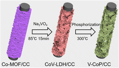
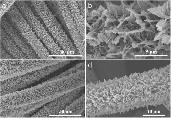
The synthesis process of the V-CoP/CC nanosheet array is shown in Fig. 1. Co-MOF/CC nanosheet arrays were prepared on CC cloth by co-precipitation method with Co(NO3)2·6H2O and 2-methylimidazole aqueous solution as main raw materials. Co-MOF grew uniformly and vertically on the CC surface. SEM images showed that Co-MOF was in the shape of a three-dimensional blade (Fig. S1†), with a smooth surface and a thickness of about 100 nm. The XRD results (Fig. S2†) show that the diffraction peaks at 25.5 and 43.5° are attributed to carbon cloth, and the XRD peaks after Co-MOFs grow on the surface are consistent with previous literature, indicating that the synthesis of Co-MOF/CC is successful.14Subsequently, Co-MOF/CC is converted to V-Co-LDH/CC by ion exchange. Due to the hydrolysis of Co-MOF, the released Co2+ is ion exchanged with OH− and VO43− to form V-Co layered bi-hydride (V-Co LDH) on the surface.15,16 As seen from the SEM results, the V-Co(OH)2/CC catalyst presents a three-dimensional lamellar structure with a large number of nanosheets attached to the surface (Fig. 2). Besides, the weak X-ray diffraction peak of V-Co(OH)2/CC is consistent with the standard JCPDS (no. 51-1731) assigned to Co(OH)2, further confirming the successful conversion of Co-MOF to V-Co(OH)2 on the carbon cloth (Fig. S3†).
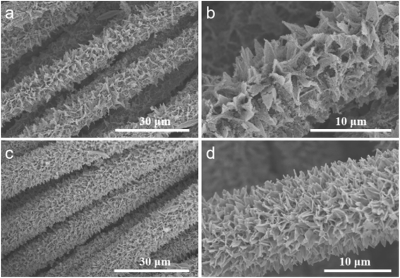
After the phosphating process at 350 °C under an N2 atmosphere, the morphology changes of V-CoP/CC, as shown in Fig. 3. SEM results show that the originally smooth nanosheet array (Fig. 3a and b) becomes rough and porous (Fig. 3c and d). Fig. 6 shows the V-CoP/CC vertical nanochannel array after phosphating without collapse and aggregation, indicating a firm contact between V-CoP and CC cloth. Vertically aligned CoP nanoarrays with three-dimensional open frames can not only maximize the exposed reaction sites, but also greatly promote the acquisition of electrolytes and the release of hydrogen during the HER process, thus significantly improving HER catalytic performance.17 Fig. S4† shows the XRD pattern of the prepared V-COP/CC catalyst. The results show that all diffraction peaks, except the carbon cloth peak, belong to CoP (JCPDS: 65-1474), and no diffraction peaks of V-based compounds are found, indicating that V atoms are doped into the CoP lattice during phosphating.
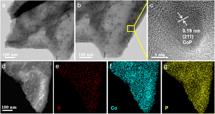
The morphology and element distribution of V-CoP/CC were characterized by transmission electron microscopy (TEM), high-resolution transmission electron microscopy (HRTEM) and energy dispersion spectrometer (EDS), as shown in Fig. 8. TEM images confirmed that the surface of the V-CoP nanosheet array was composed of nanoparticles (Fig. 4a), which was consistent with SEM results. According to HRTEM results (Fig. 4c), the lattice spacing of the V-CoP is 0.19 nm, attributed to the CoP (211) plane. Additionally, the HAADF-STEM image of V-CoP and the corresponding EDS element mapping image are shown in Fig. 4e–g. It can be seen that the elements V, Co and P are evenly distributed on the entire surface of the V-CoP sample, indicating that the element V is uniformly doped on the CoP.
The surface chemical composition of V-CoP/CC was analyzed by X-ray photoelectron spectroscopy (XPS). As shown in Fig. 5a, the XPS spectrum of the prepared sample shows the presence of elements V, Co and P. Fitting the V 2p peaks (Fig. 5b), the peaks at the binding energies (Bes) of 516.5 and 517.5 eV are attributed to V4+ and V5+, respectively, suggesting that V species exist in the lattice of V-CoP/CC as V4+ and V5+.18 In the Co 2p XPS spectrum (Fig. 5c), there are two peaks at 784.6 and 803.1 eV with a satellite peak, among which the spin orbit twin peaks at 779.1 and 794.3 eV are attributed to the Co–P bond.19 The spin orbit twin peaks at 781.6 and 798.3 eV correspond to the CoOx.20 The high-resolution P 2p spectrum has three main peaks from the P 2p3/2, P 2p1/2 and P–O bonds at 129.9, 130.7 and 134.3 eV, respectively (Fig. 5d).
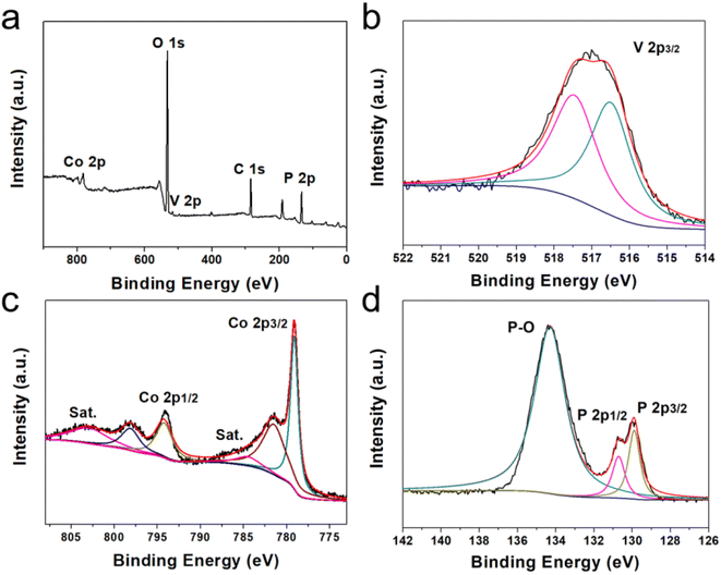 | ||
| Fig. 5 (a) Full XPS spectrum of V-CoP@C and high resolution spectra of (b)–(d) V 2p, Co 2p and P 2p. | ||
3.2 Electrocatalytic hydrogen evolution performance of V-CoP@C
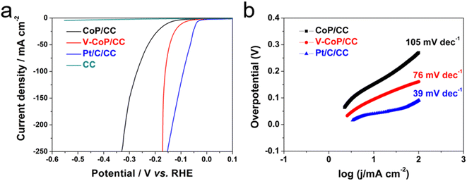
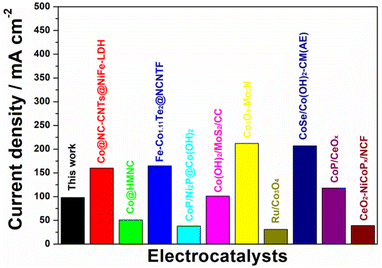
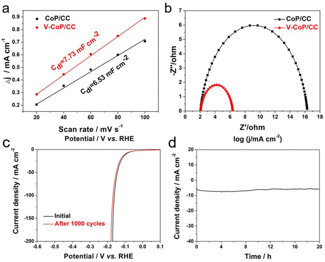
The electrocatalytic properties of Pt/C/CC, CoP/CC and V-CoP/CC in 1.0 M KOH solution were recorded using a three-electrode system. Fig. 6a shows that at a current density of 10 mA cm−2, the overpotential of the Pt/C/CC catalyst is 39 mV, indicating the best HER reaction activity. The overpotential of V-CoP/CC at a current density of 10 mA cm−2 is only 98 mV, which is much lower than the catalytic performance of CoP (149 mV). This indicates that V doping plays a key role in improving the performance of the CoP catalyst. The HER performance of V-CoP/CC was much more optimal than the other Co-based catalysts from the recent literature (Table S1†and Fig. 7). To evaluate HER kinetics, the Tafel slopes of the three catalysts were tested, and the results are shown in Fig. 6b. As can be seen from these results, the slope values of CoP/CC, V-CoP/CC and Pt/C/CC catalysts are 105 mV dec−1, 76 mV dec−1 and 39 mV dec−1, respectively. The comparison shows that V-CoP/CC has better reaction kinetics and faster charge transfer than CoP/CC in alkaline electrolytes.Fig. S5† shows the cyclic voltammetry (CV) of CoP/CC and V-CoP/CC. The double-layer capacitance (Cdl) was also evaluated using electrochemically active surface area (ECSA) (Fig. 8). The V-CoP/CC catalyst was observed to have a higher electrochemical surface area than the CoP/CC catalyst at different sweep voltammetry of 20–100 mV s−1(scan rate: 20, 40, 60, 80, 100 mV s−1) at the potential range of 0.06–0.2 V.21–24 The Cdl value of the V-CoP/CC electrode was 7.73 mF cm−2, which was much higher than that of CoP/CC (6.53 mF cm−2), indicating that more active sites were exposed on the catalysts surface during the reaction. This further indicated that V-doping promotes electrolyte acquisition and H2 gas release in the HER process, significantly improving HER catalytic performance. The comparison of the Nyquist plots of the catalyst confirmed that the interfacial electron transfer resistance (Rct) of V-CoP/CC was less than that of CoP/CC (Fig. 8b). These results demonstrate that the V-CoP/CC catalyst has the highest conductivity and the fastest interfacial electron transfer during the alkaline HER process.25,26
Electrochemical stability is another important factor in evaluating the excellent performance of HER electrocatalysts.27,28 In a 1.0 M KOH solution, the V-CoP/CC catalyst underwent a 1000 CV cycles test and chrono-current performance test. The stability test results are shown in Fig. 8c and d. The LSV curve after 1000 CV cycles was well overlapped with the initial one, and the performance attenuation of the V-CoP/CC catalyst was negligible compared to the first cycle of 1000 consecutive CV tests, indicating its superior stability in alkaline conditions. The SEM images reveal that the V-CoP/CC catalyst maintained its rough and porous morphology after stability testing, demonstrating good structural stability of the catalyst (Fig. S6a†). Furthermore, XRD pattern of the V-CoP/CC catalyst after stability testing was consistent with the pattern of CoP, indicating that the crystalline structure was maintained during the stability testing (Fig. S6b†). In addition, the V-CoP/CC catalyst showed good stability after continuous electrolysis for 20 h (Fig. 8d), with little increase in potential. In summary, the results demonstrate that the V-CoP/CC catalyst has good long-term stability for HER in an alkaline solution.
4 Conclusion
In this study, the Co-foundation organic framework (ZIF-67) was grown on a flexible carbon cloth (CC), followed by prepared V-doped CoP nanosheet array (V-CoP/CC) using a simple in situ ion exchange/phosphating method. This method allowed for the in situ generation of V-CoP/CC on a CC cloth with high conductivity, eliminating the need for separate synthesis. Scanning electron microscopy (SEM) results showed that the V-CoP/CC surface had a rough three-dimensional blade-like structure, which increased the electrochemical surface area, facilitated faster electron transport, and exposed more catalytic active sites. Additionally, doping V ions promoted electrolyte acquisition and H2 gas release during the HER process, while the synergistic effect of V and Co atoms further improves HER performance. The three-dimensional blade structure of the V-CoP/CC catalyst demonstrated high reaction stability for HER in an alkaline solution, with an overpotential of 98 mV at a current density of 10 mA cm−2. This work provides a new strategy for the development of Pt-based non-noble metal electrocatalysts.Conflicts of interest
There are no conflicts to declare.Acknowledgements
This work was financially supported by the National Natural Science Foundation of China (No. 21603069), Students innovation and entrepreneurship training program of Huzhou University (202201253), Start-up funding for talent research in 2022 (RK33047), the Public Welfare Application Research Project of Huzhou City (grant numbers 2021GZ09).References
- X. Y. Zhao, B. L. He, J. Zhang, C. F. Du, Q. Ye and S. J. Liu, Vacuum, 2022, 198, 110888 CrossRef CAS.
- L. Sun, T. Wang, L. Zhang, Y. J. Sun, K. W. Xu, Z. F. Dai and F. Ma, J. Power Sources, 2018, 377, 142–150 CrossRef CAS.
- X. C. Du, J. W. Huang, J. J. Zhang, Y. C. Yan, C. Y. Wu, Y. Hu, C. Y. Yan, T. Y. Lei, W. Chen, C. Fan and J. Xiong, Angew. Chem., Int. Ed., 2019, 58, 4484–4502 CrossRef CAS PubMed.
- R. L. Zhu, F. F. Chen, J. Y. Wang, Y. Y. Song, J. L. Cheng, M. Mao, H. J. Ma, J. J. Lu and Y. L. Cheng, Nanoscale, 2020, 12, 9144–9151 RSC.
- G. Zhang, B. Wang, J. Bi, D. Fang and S. Yang, J. Mater. Chem. A, 2019, 7, 5769–5778 RSC.
- Y. Zheng, Y. Jiao, A. Vasileff and S. Z. Qiao, Angew. Chem., Int. Ed., 2017, 57, 7568–7579 CrossRef PubMed.
- X. Wang, Z. J. Ma, L. L. Chai, L. Q. Xu, Z. Y. Zhu, Y. Hu, J. J. Qian and S. M. Huang, Carbon, 2019, 141, 643–651 CrossRef CAS.
- H. Furukawa, K. E. Cordova, M. O'Keeffe and O. M. Yaghi, Science, 2013, 341, 1230444 CrossRef PubMed.
- L. Wang, N. Gong, Z. Zhou, Q. C. Zhang, W. C. Peng, Y. Li and F. B. Zhang, Chin. J. Catal., 2022, 43, 1176–1183 CrossRef CAS.
- Y. Lian, H. Sun, X. Wang, P. Qi, Q. Mu, Y. Chen, J. Ye, X. Zhao, Z. Deng and Y. Peng, Chem. Sci., 2019, 10, 464–474 RSC.
- Y. Pan, K. Sun, Y. Lin, X. Cao, Y. S. Cheng, S. J Liu, L. Y. Zeng, W. C. Cheong, D. Zhao, K. L. Wu, Z. Liu, Y. Q. Liu, D. S. Wang, Q. Peng, C. Chen and Y. D. Li, Nano Energy, 2019, 56, 411–419 CrossRef CAS.
- J. Q. Zhou, Y. L. Xie, L. Yang, Y. S. Liu, Y. Du, L. Yu and Y. Yu, Inorg. Chem. Front., 2023, 10, 2842–2859 RSC.
- Z. Zhang, X. Ma and J. Tang, J. Mater. Chem. A, 2018, 6, 12361–12369 RSC.
- M. Sun, Q. Ye, L. Lin, Y. F. Wang, Z. M. Zheng, F. F. Chen and Y. L. Cheng, J. Colloid Interface Sci., 2023, 637, 262–270 CrossRef CAS PubMed.
- J. T. Zhang, H. Hu, Z. Li and X. W. Lou, Angew. Chem., Int. Ed., 2016, 128, 4050–4054 CrossRef.
- X. H. Du, Y. N. Fang, J. B. Guan, S. S. Li, L. N. Wang and M. Zhang, Int. J. Hydrogen Energy, 2021, 46, 599–608 CrossRef CAS.
- L. Y. Zeng, K. A. Sun, X. B. Wang, Y. Q. Liu, Y. Pan, Z. Liu, D. W. Cao, Y. Song, S. H. Liu and C. G. Liu, Nano Energy, 2018, 51, 26–36 CrossRef CAS.
- Y. F. Cheng, F. Liao, W. Shen, L. B. Liu, B. B. Jiang, Y. Q. Li and M. W. Shao, Nanoscale, 2017, 9, 18977 RSC.
- S. B. Guo, W. B. Zhang, Z. Q. Yang, S. S. Chai, X. L. Zhang, X. Zhou, X. W. Han and J. P. Long, J. Alloys Compd., 2023, 944, 169160 CrossRef CAS.
- C. Xu, Y. Q. Jiang, J. H. Yang, W. M. Wu, X. Qian and L. X. Hou, Chem. Eng. J., 2018, 343, 86–94 CrossRef CAS.
- Y. F. Cheng, F. Liao, W. Shen, L. B. Liu, B. B. Jiang, Y. Q. Li and M. W. Shao, Nanoscale, 2017, 9, 18977–18982 RSC.
- Y. R. Ren, P. C. Ye, J. D. Chen, H. Y. Wang, J. Q. Ning, J. L. Shen, Y. J. Zhong and Y. Hu, J. Power Sources, 2022, 545, 231908 CrossRef CAS.
- L. Yan, B. B. Xie, C. Yang, Y. H. Wang, J. Q. Ning, Y. J. Zhong and Y. Hu, Adv. Energy Mater., 2023, 13, 2204245 CrossRef CAS.
- X. H. Chen, K. Niu, Z. Y. Xue, X. D. Liu, B. G. Liu, B. Zhang, H. Zeng, W. Lv, Y. M. Zhang and Y. Wu, Nanoscale Adv., 2022, 4, 1639–1648 RSC.
- B. He, P. Zhao, G. X. Pan, Q. Lu, H. Q. Li, F. Ye, Y. W. Tang, Q. L. Hao and Z. Su, J. Alloys Compd., 2023, 938, 168673 CrossRef CAS.
- Y. K. Sun, W. Y. Sun, G. C. Li, L. Wang, J. F. Huang, A. Meng and Z. J. Li, J. Mater. Chem. A, 2023, 11, 2262–2272 RSC.
- L. Yan, Z. Y. Xu, X. N. Liu, S. Mahmood, J. L. Shen, J. Q. Ning, S. Li, Y. J. Zhong and Y. Hu, Chem. Eng. J., 2022, 446, 137049 CrossRef CAS.
- H. Y. Wang, Y. K. Jiao, S. J. Wang, P. C. Ye, J. Q. Ning, Y. J. Zhong and Y. Hu, Small, 2021, 17, 2103517 CrossRef CAS PubMed.
Footnotes |
| † Electronic supplementary information (ESI) available. See DOI: https://doi.org/10.1039/d3na00348e |
| ‡ These authors contributed equally to this work. |
| This journal is © The Royal Society of Chemistry 2023 |

