
 Open Access Article
 This Open Access Article is licensed under a Creative Commons Attribution-Non Commercial 3.0 Unported Licence
Effect of steric hindrance on the interfacial connection of MOF-on-MOF architectures†
Junsu
Ha‡
 a,
Mingyu
Jeon‡
b,
Jihyun
Park
a,
Jihan
Kim
*b and
Hoi Ri
Moon
*c
a,
Mingyu
Jeon‡
b,
Jihyun
Park
a,
Jihan
Kim
*b and
Hoi Ri
Moon
*c
aDepartment of Chemistry, School of Natural Science, Ulsan National Institute of Science and Technology (UNIST), Ulsan 44919, Republic of Korea
bDepartment of Chemical and Biomolecular Engineering, Korea Advanced Institute of Science and Technology (KAIST), Daejeon, Republic of Korea
cDepartment of Chemistry and Nanoscience, Ewha Womans University, Seoul 03760, Republic of Korea. E-mail: hoirimoon@ewha.ac.kr
First published on 6th March 2023
Abstract
MOF-on-MOF is attracting great attention due to its improved and/or synergistic properties not exhibited in a single MOF. In particular, the non-isostructural pairs of MOF-on-MOFs can have great potential induced by large heterogeneity, which enables diverse applications in a wide range of fields. HKUST-1@IRMOF is a fascinating platform because the alteration of the IRMOF pores with bulkier substituent groups on the ligands can provide a more microporous environment. However, the sterically hindered linker can affect the seamless growth at the interface, an important issue in practical research fields. Despite many efforts to reveal the growth of a MOF-on-MOF, there is still a lack of studies on a MOF-on-MOF consisting of a sterically hindered interface. Indeed, the effect of a bulky linker at an interface of HKUST-1@IRMOF, a non-isostructural MOF-on-MOF system, has not yet been reported, and thus, how the interfacial strain affects the interfacial growth remains unknown. In this study, we investigate the effect of an interfacial strain on a chemical connection point in an MOF-on-MOF system through a series of theoretical and synthetic experiments using a HKUST-1@IRMOF system. Our results reveal the importance of the proximity of each coordinating site at a MOF-on-MOF interface as well as lattice parameter matching for an effective secondary growth to achieve a well-connected MOF-on-MOF.
Introduction
MOF-on-MOF structures, a special subset of composite MOFs, are attracting considerable attention owing to their unprecedented synergistic properties.1–4 From a synthetic viewpoint, a well-matched lattice induces the growth of defect-free single-crystalline secondary MOFs,5–7 while a mismatched lattice can easily cause a defect formation or polycrystalline growth at the interface instead of epitaxial growth.8,9 Selecting a pair of isostructural MOFs is an easily accessible strategy to construct a well-connected heterostructure. A more heterogeneous system consisting of a non-isostructural combination can significantly expand the MOF-on-MOF structure search space to induce unprecedented functionality. However, the selection of an appropriate MOF pair with a well-matched lattice is difficult, resulting in only a few examples being reported. Additionally, a comprehensive understanding of the interfacial configuration at the molecular scale for a non-isostructural MOF-on-MOF has not yet been conducted.Recently, Kim and Moon et al.10 presented a computational algorithm based on lattice parameters and chemical connection point matching to extract non-isoreticular MOF-on-MOF candidates and synthesised well-connected single-crystalline MOF-on-MOFs, such as HKUST-1@IRMOF-1, UiO-67@HKUST-1, and UiO-66@MIL-88B. The joint computational-experimental approach shed light on the discovery of non-isostructural MOF-on-MOF pairs, and the rational computational structure modelling provided an understanding of the interfacial coordination environment. The second MOF in the suggested MOF-on-MOF pair was grown on the core MOF as a single-crystalline shell with a seamless interface, which is considered an important feature in practical research fields as it can provide defect-free unification.11,12
Several MOF-on-MOF heterostructures with microporous MOFs in the outer shell MOF have exhibited enhanced separation selectivity. For example, Rosi et al.13 utilised the N2 exclusive pore size of bio-MOF-14 in the shell of bio-MOF-11@bio-MOF-14 to improve CO2/N2 selectivity. Using a similar strategy, Kitagawa et al.14 proposed an isomer mixture (cetane/isocetane) separation method using the diffusion barrier effect of shell MOFs. Coronas et al.15 integrated ZIF-7 possessing smaller pore sizes (3.0 Å) and a ZIF-8 (3.4 Å) layer to separate H2 (2.9 Å) from larger molecules, such as CO2 (3.3 Å) and CH4 (3.8 Å). In 2020, Fischer et al.16 presented a large volatile organic compound (VOC) uptake induced by a novel MOF-on-MOF system. The pore size of the MOFs in the bottom layer was insufficient to take up VOC molecules. However, the secondary grown MOF layer induced VOC diffusion, which is described as the “funnel effect,” that eliminated pore blockage problems in the original MOF. The aforementioned MOF-on-MOFs exhibited improved separation performance compared to the original MOFs based on their enhanced pore environment.
Likewise, the integration of different MOFs with pore-tuned systems and reservoir-acting MOFs in a single system is important for maximising selective molecular separation. For this reason, HKUST-1@IRMOF (HKUST@IR) systems have great potential for various molecule separation applications because the IRMOF shells can easily alter the pore environment (Scheme 1). This is achieved by the simple modulation of benzenedicarboxylic acid (BDC)-based linkers with bulkier substituent groups, which can endow a more microporous environment to the shell region.17,18 Furthermore, HKUST can act as a reservoir for enhancing the gas storage ability during the separation process.
 | ||
| Scheme 1 HKUST-1@IRMOF exhibiting an effective pore size modularity. The sky blue core region illustrates the HKUST-1 structure, while the outer shell layer is the IRMOF. | ||
Notably, adjusting the pore size using linker modulation can cause structural instability at the MOF-on-MOF interface owing to sterically hindered bulky ligands. Previous studies6,19–21 investigated the growth of lattice-matched MOF-on-MOFs, but there is still a lack of examples of MOF-on-MOFs consisting of sterically hindered interfaces. Because the effect of a bulky linker at the interface of non-isostructural MOF-on-MOF systems has not been studied, the effect of the interfacial strain on the interfacial growth in non-isostructural MOF-on-MOFs is still not clear.
This study investigates the effect of the interfacial strain on a chemical connection point in HKUST@IR systems by combining experiments and computational simulations. Our results reveal the importance of the proximity of each coordinating site at an MOF-on-MOF interface as well as lattice parameter matching for effective secondary growth to achieve well-connected MOF-on-MOFs. This understanding can expedite the search for optimal MOF-on-MOF materials for different applications.
Experimental and computational section
Synthesis of HKUST-1 (HKUST)
HKUST was prepared according to a previously reported method with slight modifications.10 In a bottle (100 mL), Cu(NO3)2·2.5H2O (2.36 g, 10.1 mmol) was dissolved in an H2O/N,N-dimethylformamide (DMF) mixture (1![[thin space (1/6-em)]](https://www.rsc.org/images/entities/char_2009.gif) :1, 30 mL). 1,3,5-Benzene-tricarboxylic acid (H3BTC) (1.8 g, 8.57 mmol) was dissolved in ethanol (22.5 mL) with slight heating and stirring. To the copper nitrate solution, the H3BTC solution was added followed by the addition of glacial acetic acid (60 mL). The solution was swirled and placed in an oven at 55 °C for 24 h. The supernatant was then quickly decanted, and the resultant octahedral-shaped blue crystals were washed with fresh ethanol.
:1, 30 mL). 1,3,5-Benzene-tricarboxylic acid (H3BTC) (1.8 g, 8.57 mmol) was dissolved in ethanol (22.5 mL) with slight heating and stirring. To the copper nitrate solution, the H3BTC solution was added followed by the addition of glacial acetic acid (60 mL). The solution was swirled and placed in an oven at 55 °C for 24 h. The supernatant was then quickly decanted, and the resultant octahedral-shaped blue crystals were washed with fresh ethanol.
Synthesis of dimethyl-2,5-dihydroxyterephthalate22
Dimethyl cyclohexanedione carboxylate (82.8 g, 0.364 mol) was added to acetic acid (256 mL), and the solution was heated to 80 °C. N-Chlorosuccinimide (50.0 g, 0.374 mol) was slowly added and the reaction mixture was stirred for 1 h. After cooling to room temperature, the yellow precipitate was filtered and washed with acetic acid, water, and diethyl ether. The yellow solid was recrystallised in acetic acid and dried under vacuum to yield a yellow crystalline solid (90.2%, 70.5 g). 1H NMR (CDCl3) δ/ppm 3.97 (s, 6H), 7.47 (s, 2H), 10.05 (s, 2H).Synthesis of 2,5-bis(pentoxy)-1,4-benzenedicarboxylic acid (PeBDC)23
Dimethyl-2,5-dihydroxyterephthalate (4.0 g, 17.9 mmol) and K2CO3 (7.32 g 53.0 mmol) were added in DMF (120 mL). Under an Ar atmosphere, 1-bromopentane (6.57 mL, 53.0 mmol) was added dropwise and stirred at 85 °C for 30 h. The reaction mixture was then washed with DMF, and the organic solvent was evaporated. In the same reaction vessel, water (200 mL), KOH (10 g, 178 mmol), and tetrahydrofuran (200 mL) were added with stirring at 110 °C overnight. After the evaporation of the organic solvent under reduced pressure, the concentrated solution was filtered and acidified with concentrated HCl until a pH of 2. The solution was finally filtered to yield a white to beige solid (5.23 g, 86.3%). 1H NMR (400 MHz, CDCl3) δ/ppm 11.11 (2H, s), 7.88 (2H, s), 4.30 (4H, t), 1.91 (4H, m), 1.44 (8H, m), 0.95 (6H, t).Synthesis of HKUST@IR1 (ref. 10)
HKUST@IR1 (IR1 = IRMOF-1) was prepared according to a previously reported method with minor modifications.9 In a glass jar, Zn(NO3)2·6H2O (0.760 g, 2.55 mmol) and terephthalic acid (0.132 g, 0.795 mmol) were dissolved in N,N-diethylformamide (DEF, 20 mL). HKUST crystals (5 mg) were added and well dispersed on the bottom of the glass jar. The glass jar was heated in an oven at 85 °C for 36 h. The mother liquor was quickly decanted and HKUST@IR1 crystals were washed with fresh DEF.Synthesis of HKUST@IR5
IRMOF-5 was crystallised separately or grown to non-single-crystalline HKUST@IR5 (IR5 = IRMOF-5) under conditions similar to those of HKUST@IR1. Thus, in order to grow single-crystalline HKUST@IR5, the synthetic conditions were modified. Zn(NO3)2·6H2O (0.038 g, 0.128 mmol) and PeBDC (0.013 g, 0.0807 mmol) were dissolved in DEF (20 mL) in a glass jar. Filtered HKUST crystals (5 mg) were added and well dispersed on the bottom of the glass jar. The glass jar was heated in an oven at 90 °C for 48 h until the shell MOF was grown. The mother liquor was quickly decanted and HKUST@IR5 crystals were washed with fresh DEF.Synthesis of HKUST@IR1@IR5
To 2 mL of DEF solution (2 mL) containing PeBDC (0.067 g, 0.416 mmol), N,N-diisopropylethylamine (DIPEA, 0.03 mL) dissolved in DEF (3 mL) was added under stirring. Zn(NO3)2·6H2O (0.19 g, 0.640 mmol) was dissolved in DEF (5 mL), and the mixture was then added dropwise to the PeBDC solution under stirring. One pot of HKUST@IR1 crystal was dispersed in the reaction mixture, and the mixture was heated in an oven at 85 °C for 48 h. The mother liquor was quickly decanted, and HKUST@IR1@IR5 crystals were washed with fresh DEF.Density functional theory (DFT) simulation methods
All calculations were conducted using Vienna Ab initio Simulation Package (VASP) 5.4.1 software.24,25 Projected augmented wave (PAW) pseudopotentials were used to simulate ion–electron interactions and the generalised gradient approximation (GGA) using the Perdew, Burke, and Ernzerhof (PBE) exchange–correlation functional was adopted.26 Spin polarisation was added to improve the electronic structure of dangling structures. The energy cutoff criterion of a plane wave basis set was set to 400 eV. A Hellmann–Feynman force threshold of 0.02 eV Å−1 was used to fully relax the atomic positions, and the electronic self-consistent loop break condition was adopted as 1 × 10⁻⁵ eV. Gamma centered Monkhorst–Pack k-point grids of 2 × 2 × 1 were sampled, and a large 30 Å × 30 Å × 30 Å cubic unit cell was modelled to avoid periodicity. As shown in Fig. S1,† through the (111) surface, the Cu-paddlewheel was connected to three BTC linkers and one BDC or PeBDC linker. The bonding energy of the external linker to the Cu-paddlewheel interface was obtained by eqn (1):| EBonding = ECu-paddlewheel+linker − ECu-paddlewheel − Elinker | (1) |
Interaction energy calculations
The hindered structure was extracted from the final snapshot of the MD simulation of HKUST@IR5. It was processed as an interfacial cluster that contains three Cu–paddlewheels connected with one BTC linker, which are part of HKUST, and one Zn4O connected with three PeBDC linkers, which are part of IR5 (Fig. S2a†). Then, the unhindered structure was obtained by moving the pentoxy groups far away with constrained bond lengths and angles (Fig. S2b†). The interaction energies of the pentoxy groups and Cu–paddlewheel were quantified by calculating the self-consistent field (SCF) energy difference between the hindered and unhindered structure according to eqn (2):| EInteraction = Ehindered structure (SCF) − Eunhindered structure (SCF) | (2) |
Molecular dynamics (MD) simulation methods
The HKUST@IR5 core–shell composite structure was constructed manually. The structure files of HKUST (FIQCEN) and IR5 (EDUTEC) were adapted from the Cambridge structural database (CSD).27 Each structure was cleaved via the [111] surface, and the Cu–paddlewheel of HKUST and the PeBDC linker of IR5 were connected within their interface. Periodic boundary conditions were maintained except through the z-direction (i.e. perpendicular to the interface), and the dangling bonds were capped as formic acid to ensure charge neutrality. To improve core–shell structural reliability, molecular mechanics optimisation was conducted using the Materials Studio Forcite module28 by fixing all atoms except the pentoxy groups of IR5. HKUST@IR1 was constructed by substituting the pentoxy groups to the single H atoms. The MD simulation was performed through large-scale atomic/molecular massively parallel simulator (LAMMPS) software29 within the NVT ensemble. MOF-on-MOF core–shell structures were modelled to be flexible by employing the LAMMPS-interface code that generates pair, bond, angle, dihedral, and improper force field parameters.30 The QEq charge equilibrium method and coulombic potential were added to take into account the electronic interaction. The simulation was performed for 1 ns with a time step of 1 fs at 1 bar and 298 K. Five hundred snapshots were extracted from the MD simulation trajectory and the pore limiting diameter (PLD) distribution plot was plotted using the Zeo++ software version 0.3.31 For the radial distribution function (RDF) calculation, pairwise distances were discretised and coarsely binned into the number of bins. Here, a bin was defined as a thin shell located at a certain distance from the central atom while having the thickness of the cutoff divided by the number of bins. The number of calculated pairwise distances was normalised in consideration of the number of central atoms, the number of distributed atoms, the volume of the entire simulation box, and the volume of the bin. The normalised values for each time step were averaged over 0.1 ns timescales, and the averaged values were used to plot RDF as a y-axis with respect to the corresponding distance as the x-axis.Results and discussion
Pore limiting diameter distribution of IRMOF series
Various functionalised IRMOFs were synthesised based on the IRMOF research conducted by Yaghi et al.17 To examine whether the pore size of the MOFs is more promising for small molecule separation, we calculated the PLD distribution in a few of the IRMOF candidates, including IRMOF-1, -4, -5 and -18 (1,4-BDC for IRMOF-1; 2,5-bis(propoxy)-1,4-BDC for IRMOF-4; 2,5-bis(pentoxy)-1,4-BDC for IRMOF-5; tetramethyl-1,4-BDC for IRMOF-18) (Fig. S3†). IRMOF-4 and -5 have PLDs centred near approximately 3.6 and 2.4 Å, respectively. Because H2 molecules have a kinetic diameter of 2.9 Å, the PLD of IRMOF-4 is large enough to effectively separate the molecules. In contrast, the bulkier linker of IRMOF-5 induces a more closed pore environment. It is worth noting that the phonon vibration of the alkyl chain in a cavity can induce motion that is more flexible and can open pores for small-molecule adsorption, which can lead to a more optimal environment for challenging separations.32–34 Therefore, our experiments were conducted using HKUST@IR5 (cell parameter difference: 1.9%, Table S2†) as a model system to examine the steric hindrance effect on the MOF-on-MOF synthesis.Steric hindrance effect in HKUST@IR5
HKUST@IR1 and HKUST@IR5 were prepared according to the previously reported experimental conditions corresponding to the HKUST@IR1 synthesis.10 Pre-synthesised octahedral HKUST crystals were dispersed in the IRMOF precursor solutions and solvothermally synthesised to obtain the MOF-on-MOF structure. The HKUST@IR1 crystals were successfully obtained with a morphology similar to that reported previously (Fig. 1b and S5a†). In contrast, when using the same conditions for the HKUST@IR5 synthesis, the IR5 shell tended to grow as a polycrystalline shell at the interface or individual cubic crystals instead of a solely grown single crystal shell covering the octahedral core of the MOF (Fig. S5b†). Thus, we screened various synthetic conditions for the effective epitaxial growth of IR5 at the HKUST interface. When solutions with lower concentrations were used for the secondary growth, a single-crystalline MOF-on-MOF was successfully grown, as described in Fig. 1e and S6.† The synthesised IRMOF shells are revealed as pure IR1 and IR5, which were confirmed by powder X-ray diffraction (Fig. S7†). Single crystal X-ray diffraction was conducted on the corresponding crystals obtained from crushed HKUST@IR1 and HKUST@IR5. The results confirmed that the crystalline HKUST and IR1/IR5 crystals in the core–shell architecture were intact (Table S2†).In the optical microscopy (OM) images (Fig. 1b), HKUST@IR1 exhibits a seamless interface that corresponds to previous results.10 In low and high magnification OM images (Fig. 1e and the inset), HKUST@IR5 also exhibited a well-connected interface with a single-crystalline shell. The interfacial connection was further examined by scanning electron microscopy (SEM) and energy dispersive spectroscopy (EDS). Each MOF-on-MOF crystal was embedded in an epoxy resin and sliced using an ultramicrotome to expose the interface for further analysis. As shown in Fig. S8,† both HKUST@IR1 and HKUST@IR5 interfaces were well connected without decisive defects despite the presence of an exposed surface that was cracked during the ultramicrotome sectioning. The series of microscope measurements indicate that HKUST@IR1 and HKUST@IR5 have no significant difference with both possessing a well-connected interface.
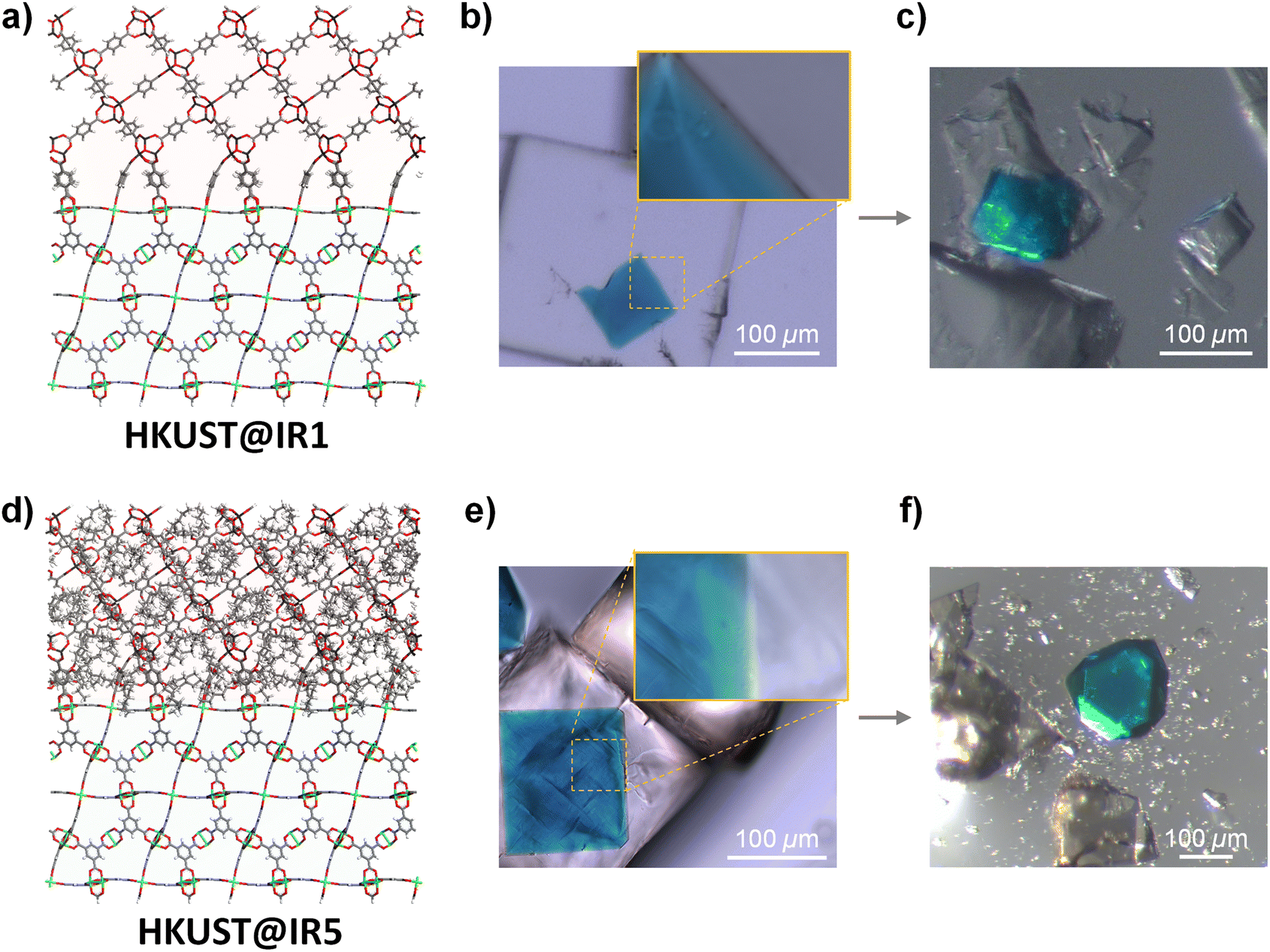 | ||
| Fig. 1 Computational structural models for (a) HKUST@IR1 and (d) HKUST@IR5 MOF-on-MOFs. Green: Cu; black: Zn; grey: C; white: H; red: O. Optical microscopy images for (b and c) HKUST@IR1 and (e and f) HKUST@IR5. Images showing the interface (b and e) before and (c and f) after the crush experiment. The insets represent the seamless interface. | ||
However, we could recognise the apparent difference in the interfacial steric hindrance effect from further examination. We crushed the interface of MOF-on-MOF crystals and observed their behaviour during breakage to elucidate the interfacial characteristics (Fig. 1c and f and videos S1–S6†). The HKUST core crystal taken from the crushed HKUST@IR1 still exhibited a firmly connected piece of the IR1 shell on its surface, which agreed with previous results,10 indicating the presence of the well-connected interface. However, the core crystal of HKUST@IR5 was easily separated from the core–shell composite upon pressing through the interface, indicating the weakly bonded interface at an atomic scale despite the well-connected interface from a macro-scale viewpoint. The aforementioned results confirm that the interfacial steric hindrance interferes with the single-crystalline growth at the MOF-on-MOF interface although the MOF pair has a well-matched crystallographic lattice, indicating the importance of chemical connection point matching.
Computational study of steric hindrance in HKUST@IR5
To elucidate how the interfacial steric hindrance affects the secondary growth at the molecular level, further mechanistic studies were conducted using a computational simulation as well as experiments. The bonding energy between the Cu–paddlewheel and BDC for HKUST@IR1 or PeBDC for HKUST@IR5 was calculated using DFT (see the Experimental and computational section for further details). The bonding energy was calculated for the Cu–paddlewheel cluster composed of three BDC ligands and a vacancy site (Fig. 2a, b, and S1†). As seen in Fig. 2a, for the HKUST@IR1 cluster, the bonding energy was −3.00 eV. However, the bonding energy of the HKUST@IR5 cluster (−2.74 eV) was weaker compared to that of the HKUST@IR1 cluster, which might be attributed to the presence of a bulky substituent in the PeBDC linker. Thus, HKUST@IR5 may have energetically unfavourable interface bonds compared to that of HKUST@IR1, which is disadvantageous for the formation of well-connected MOF-on-MOFs. | ||
| Fig. 2 Bonding energy calculation cluster model for (a) HKUST@IR1 and (b) HKUST@IR5. Ebonding indicates the bonding energy of the external linker to the Cu–paddlewheel interface. (c) The initial and final MD structures of HKUST@IR1 and HKUST@IR5. Green: Cu; black: Zn; grey: C; white: H; red: O; purple: central Cu in the radial distribution function (RDF); blue: distributed H in the RDF. (d) RDF calculation results for HKUST@IR1 and HKUST@IR5. The inset figure indicates the molecular dynamics snapshot of the HKUST@IR5 interface. Einteraction indicates the interaction energy of pentoxy groups and the Cu–paddlewheel. | ||
The pentoxy groups not only lead to the weakening of the bond between the PeBDC linker and the Cu–paddlewheel, but also cause collisions with the core MOF and other linkers. The RDF calculation was conducted using MD simulations to quantify the steric hindrance effect caused by the bulky pentoxy groups. The initial structure and final MD simulation snapshot of HKUST@IR1 and HKUST@IR5 are shown in Fig. 2c. HKUST@IR1 and HKUST@IR5 were modelled with a flexible force field so that the structures could freely vibrate and the movement of PeBDC was observed. Then, the RDF was computed with the Cu atoms in the interface serving as the central atoms (purple). The H atoms in the BDC and the pentoxy groups in HKUST@IR1 and HKUST@IR5, respectively, were the distribution atoms. The RDF calculation results of HKUST@IR1 and HKUST@IR5 are shown in Fig. 2d. The closest distance between the Cu–paddlewheel and the pentoxy groups was approximately 4 Å for HKUST@IR1. However, for HKUST@IR5, the closest distance was much closer (1.9 Å). It can be further observed in the interface of the MD snapshot shown in the inset of Fig. 2d that the Cu–paddlewheel and pentoxy groups are in close proximity to each other. Additional MD simulations with different initialisation configurations (i.e., temperature) showed similar results (Fig. S9†). In addition, the DFT interaction energy between the pentoxy group and Cu–paddlewheel in HKUST@IR5 was calculated as a negative value (−0.54 eV), which indicates that this interaction is exothermic (Fig. S2 and Table S1†). In other words, owing to the favourably close proximity of the Cu–paddlewheel and pentoxy groups, the pentoxy groups prevent a newly approaching PeBDC linker from coordinating with the surrounding Cu connection point. So far, the steric hindrance effect decreases the density of the interfacial coordination bond and induces weaker bonding than that in the HKUST@IR1 system.
The comprehensive analyses combining MD and DFT simulations reveal that two major factors cause the imperfect single crystallinity in HKUST@IR5: (1) the weakness of the bonding energy between the PeBDC linker and Cu–paddlewheel and (2) the strong steric hindrance induced by bulky pentoxy groups to prevent another PeBDC from approaching the neighbouring chemical connection points at the interface. When the PeBDC bonds to the Cu–paddlewheel in the interface, the bonding energy decreases because of its own pentoxy group. Furthermore, the bonding site in the Cu–paddlewheel is blocked due to the steric hindrance induced by the neighbouring pentoxy groups, making it difficult to produce a densely connected interface. Consequently, our theoretical analysis indicates that HKUST@IR5 may not be as robust as HKUST@IR1.
Synthetic strategy for reducing interfacial steric hindrance
Even if we want to introduce a specific IRMOF into the core–shell MOF for efficient separation of small molecules, its unification into single-crystalline MOF-on-MOFs is difficult owing to steric hindrance at the interface. To overcome this limitation, we introduced a doubly layered MOF-on-MOF approach (Fig. 3a). IR1 as the first shell can serves as a useful buffer layer that provides a good connection to both the core (HKUST) and bulkier shell (IR5). To synthesise the double-layered structure, IR1 was grown on the HKUST crystal and the as-prepared HKUST@IR1 crystal was immersed in an IR5 synthetic solution for further shell growth. Notably, the Zn4O cluster of IR1 is vulnerable to acidic conditions provided by the cation and the ligand precursors and is destroyed during the secondary shell growth. To reduce the chemical decomposition, a stoichiometric amount of N,N-diisopropylethylamine (DIPEA), referred to as a Hünig's base, was added to the solution to act as a proton scavenger6 as its sterically hindered environment makes it a good base but a poor nucleophile. DIPEA only captured the created proton but did not participate in the interfacial reaction. As a result, the double-layered HKUST@IR1@IR5 was successfully synthesised with well-connected interfaces (Fig. 3b and S10†). The interfacial connection between HKUST and the IR1 layer was well maintained after the sequential reaction. The crushed interface of HKUST and IR1 exhibited the same trends as the original HKUST@IR1 crystal (Fig. 3c). Additionally, the IR1@IR5 interface was firmly maintained, as described in videos S7–S9,† indicating that the double-layered MOF-on-MOF synthesis strategy was suitable to impart sterically hindered organic linkers at an interface while maintaining strong connections at the interface of the MOF-on-MOF system. | ||
| Fig. 3 (a) Scheme of the image for a doubly layered MOF-on-MOF and a computational structural model for HKUST@IR1@IR5. Green: Cu; black: Zn; grey: C; white: H; red: O. Optical microscopy images of the synthesised HKUST@IR1@IR5 when (b) whole and (c) crushed. | ||
Conclusions
This study investigated the effect of steric hindrance at the interface of a non-isostructural MOF-on-MOF. Despite the benefits of bulky organic linkers that can impart various functionalities in MOFs, they can induce weak connections at the interface of MOF-on-MOFs owing to their sterically hindered bulky substituents. A series of experiments revealed the existence of the steric hindrance effect in the HKUST@IR5 system, which contained bulky substituents at the shell MOF. The interface of HKUST@IR5 was not different from that of the sterically non-hindered HKUST@IR1. However, it exhibited weaker interfacial connections, as was shown by crush experiments. To elucidate this phenomenon, DFT and MD simulations were conducted, and the results revealed that the energetically unfavoured interfacial cluster and the low density of the interfacial connections of HKUST@IR5 led to a weakened interface. To overcome these issues, we presented a double-layered MOF-on-MOF, which demonstrated ways in which one can fine-tune the pore size while retaining the clean surface of the composite structures. We expect that the well-integrated system has great potential in challenging gas separation applications, such as isotope separation.Author contributions
J. H. and M. J. conceived the project and developed the idea. J. H. and J. P. synthesised and characterised the MOF-on-MOF materials. M. J. performed the computational calculations. H. R. M. and J. K. formulated the project. All authors contributed to writing/revising the paper.Conflicts of interest
There are no conflicts to declare.Acknowledgements
This work was supported by the Samsung Research Funding & Incubation Center of Samsung Electronics under Project Number SRFC-MA1702-51.Notes and references
- J. Ha and H. R. Moon, CrystEngComm, 2021, 23, 2337–2354 RSC.
- D. H. Hong, H. S. Shim, J. Ha and H. R. Moon, Bull. Korean Chem. Soc., 2021, 42, 956–969 CrossRef CAS.
- C. Liu, J. Wang, J. Wan and C. Yu, Coord. Chem. Rev., 2021, 432, 213743 CrossRef CAS.
- S. Cho, C. Park, M. Jeon, J. H. Lee, O. Kwon, S. Seong, J. Kim, I.-D. Kim and H. R. Moon, Chem. Eng. J., 2022, 449, 137780 CrossRef CAS.
- K. Koh, A. G. Wong-Foy and A. J. Matzger, Chem. Commun., 2009, 6162–6164, 10.1039/B904526K.
- Y. Yoo and H.-K. Jeong, Cryst. Growth Des., 2010, 10, 1283–1288 CrossRef CAS.
- J. I. Feldblyum, M. Liu, D. W. Gidley and A. J. Matzger, J. Am. Chem. Soc., 2011, 133, 18257–18263 CrossRef CAS PubMed.
- X. Yang, S. Yuan, L. Zou, H. Drake, Y. Zhang, J. Qin, A. Alsalme and H.-C. Zhou, Angew. Chem., Int. Ed., 2018, 57, 3927–3932 CrossRef CAS PubMed.
- L. Zhang, J. Wang, X. Ren, W. Zhang, T. Zhang, X. Liu, T. Du, T. Li and J. Wang, J. Mater. Chem. A, 2018, 6, 21029–21038 RSC.
- O. Kwon, J. Y. Kim, S. Park, J. H. Lee, J. Ha, H. Park, H. R. Moon and J. Kim, Nat. Commun., 2019, 10, 3620 CrossRef PubMed.
- C. Wu, K. Zhang, H. Wang, Y. Fan, S. Zhang, S. He, F. Wang, Y. Tao, X. Zhao, Y.-B. Zhang, Y. Ma, Y. Lee and T. Li, J. Am. Chem. Soc., 2020, 142, 18503–18512 CrossRef CAS PubMed.
- F. Wang, H. Wang and T. Li, Nanoscale, 2019, 11, 2121–2125 RSC.
- T. Li, J. E. Sullivan and N. L. Rosi, J. Am. Chem. Soc., 2013, 135, 9984–9987 CrossRef CAS PubMed.
- K. Hirai, S. Furukawa, M. Kondo, H. Uehara, O. Sakata and S. Kitagawa, Angew. Chem., Int. Ed., 2011, 50, 8057–8061 CrossRef CAS PubMed.
- J. Sánchez-Laínez, A. Veiga, B. Zornoza, S. R. Balestra, S. Hamad, A. R. Ruiz-Salvador, S. Calero, C. Téllez and J. Coronas, J. Mater. Chem. A, 2017, 5, 25601–25608 RSC.
- Z. Wang, S. Wannapaiboon, S. Henke, M. Paulus, K. Rodewald, B. Rieger and R. A. Fischer, J. Mater. Chem. A, 2020, 8, 12990–12995 RSC.
- M. Eddaoudi, J. Kim, N. Rosi, D. Vodak, J. Wachter, M. O'Keeffe and O. M. Yaghi, Science, 2002, 295, 469–472 CrossRef CAS PubMed.
- O. M. Yaghi, M. O'Keeffe, N. W. Ockwig, H. K. Chae, M. Eddaoudi and J. Kim, Nature, 2003, 423, 705–714 CrossRef CAS PubMed.
- S. Furukawa, K. Hirai, K. Nakagawa, Y. Takashima, R. Matsuda, T. Tsuruoka, M. Kondo, R. Haruki, D. Tanaka, H. Sakamoto, S. Shimomura, O. Sakata and S. Kitagawa, Angew. Chem., Int. Ed., 2009, 48, 1766–1770 CrossRef CAS PubMed.
- S. Choi, T. Kim, H. Ji, H. J. Lee and M. Oh, J. Am. Chem. Soc., 2016, 138, 14434–14440 CrossRef CAS PubMed.
- V. Chernikova, O. Shekhah, I. Spanopoulos, P. N. Trikalitis and M. Eddaoudi, Chem. Commun., 2017, 53, 6191–6194 RSC.
- G. N. Short, H. T. Nguyen, P. I. Scheurle and S. A. Miller, Polym. Chem., 2018, 9, 4113–4119 RSC.
- D. J. Ashworth, T. M. Roseveare, A. Schneemann, M. Flint, I. Dominguez Bernáldes, P. Vervoorts, R. A. Fischer, L. Brammer and J. A. Foster, Inorg. Chem., 2019, 58, 10837–10845 CrossRef CAS PubMed.
- G. Kresse and J. Furthmüller, Phys. Rev. B, 1996, 54, 11169 CrossRef CAS PubMed.
- G. Kresse and J. Furthmüller, Comput. Mater. Sci., 1996, 6, 15–50 CrossRef CAS.
- J. P. Perdew, K. Burke and M. Ernzerhof, Phys. Rev. Lett., 1996, 77, 3865 CrossRef CAS PubMed.
- C. R. Groom, I. J. Bruno, M. P. Lightfoot and S. C. Ward, Acta Crystallogr., Sect. B: Struct. Sci., Cryst. Eng. Mater., 2016, 72, 171–179 CrossRef CAS PubMed.
- BIOVIA and Dassault Systèmes, Materials Studio, 2019 Search PubMed.
- S. Plimpton, Comput. Mater. Sci., 1995, 4, 361–364 CrossRef CAS.
- P. G. Boyd, S. M. Moosavi, M. Witman and B. Smit, J. Phys. Chem. Lett., 2017, 8, 357–363 CrossRef CAS PubMed.
- T. F. Willems, C. H. Rycroft, M. Kazi, J. C. Meza and M. Haranczyk, Microporous Mesoporous Mater., 2012, 149, 134–141 CrossRef CAS.
- H. Oh, S. B. Kalidindi, Y. Um, S. Bureekaew, R. Schmid, R. A. Fischer and M. Hirscher, Angew. Chem., Int. Ed., 2013, 52, 13219–13222 CrossRef CAS PubMed.
- M. Liu, L. Zhang, M. A. Little, V. Kapil, M. Ceriotti, S. Yang, L. Ding, D. L. Holden, R. Balderas-Xicohténcatl, D. He, R. Clowes, S. Y. Chong, G. Schütz, L. Chen, M. Hirscher and A. I. Cooper, Science, 2019, 366, 613–620 CrossRef CAS PubMed.
- L. Zhang, S. Jee, J. Park, M. Jung, D. Wallacher, A. Franz, W. Lee, M. Yoon, K. Choi, M. Hirscher and H. Oh, J. Am. Chem. Soc., 2019, 141, 19850–19858 CrossRef CAS PubMed.
Footnotes |
| † Electronic supplementary information (ESI) available. See DOI: https://doi.org/10.1039/d2na00790h |
| ‡ These authors contributed equally. |
| This journal is © The Royal Society of Chemistry 2023 |