
 Open Access Article
 This Open Access Article is licensed under a Creative Commons Attribution-Non Commercial 3.0 Unported Licence
Modeling of a two-stage polymerization considering glass fibre sizing using molecular dynamics†
Lukas
Schöller
 *ab,
Britta
Nestler
ab and
Colin
Denniston
c
*ab,
Britta
Nestler
ab and
Colin
Denniston
c
aInstitute for Applied Materials (IAM-MMS), Karlsruhe Institute of Technology (KIT), Kaiserstrasse 12, 76131 Karlsruhe, Germany. E-mail: lukas.schoeller@kit.edu
bInstitute of Digital Materials Science (IDM), Karlsruhe University of Applied Sciences, Moltkestrasse 30, 76133 Karlsruhe, Germany
cDepartment of Physics & Astronomy, University of Western Ontario (UWO), 1151 Richmond Street, London, ON N6A 3K7, Canada
First published on 22nd November 2022
Abstract
Fibre reinforced polymers are an important class of materials due to their light weight, high strength, and stiffness. However, there is a lack of knowledge about the interaction of fibre surface, sizing (fibre coating), and resin. Often only idealised academic systems are studied, and only rarely realistic systems that are used in an industrial context. Therefore, methods for studying the behaviour of complex sizing are highly desirable, especially as they play a crucial role in the performance of fibre reinforced polymers. Here, a simplified, yet industrially used resin system is extended using molecular dynamics simulations by adding a fibre surface and sizing layers. Furthermore, a common coupling agent was selected, and several additional assumptions were made about the structure of the sizing. Based on this, a systematic procedure for the development of a final cured system is introduced: a condensation reaction to form oligomers from coupling agent monomers is conducted. Subsequently, a two stage reaction, a polyurethane reaction and a radical polymerisation, is modelled based on an established approach. Using the final cured system, evaluations of averaged quantities during the reactions are carried out. Moreover, the system is evaluated along the normal direction of the fibre surface, which proves a spatial analysis of the fibre–sizing–resin interface.
1 Introduction
Fibre-reinforced polymers (FRP) are increasingly important in industrial applications, including aerospace, automotive, marine, and construction industries. The majority of these are glass fibre reinforced polymers, probably due to the relatively low cost, while still offering good performance. A relatively new thermoset matrix material in this context is the unsaturated polyester polyurethane hybrid (UPPH) resin system. It combines a polyurethane (PU) polyaddition with a radical polymerisation of unsaturated polyester (UP), resulting in a two-step reaction of the thermoset. The hybrid networks formed by this copolymerisation increase overall properties such as crack resistance, tensile strength and toughness.1 Therefore, there is increasing interest in using this material in industrial applications such as the automotive industry.2Besides the matrix material and the fibre, the sizing (fibre coating) plays a crucial role in the manufacturing and performance of FRPs. The fibre size consist of multiple components and fulfils a variety of tasks, such as protection of the fibre, improvement of the fibre handling, or enhancement of the adhesive bonding of fibre and matrix.3 Early investigations considering the sizing were conducted by Plueddemann4,5 and Lowenstein.6 They mainly focus on the coupling agent, which provides the functionality of bonding to both the glass fibre and the resin. In the literature, Thomason,7–9 Gao and Mäder10 and Liu et al.,11 among others, examined the sizing of glass fibres with different sizing formulations and using various approaches. Furthermore, Karger-Kocsis et al.12 summarise recent advances in interphase technology for several fibres, and matrix materials, as well as sizes. Also, Thomason3 recently gave a detailed overview of glass fibre sizing. He pointed out that the actual sizing is always a proprietary secret that leads to a lack of understanding of the fibre sizing, especially since the knowledge is very fragmented. As the fibre interphase is a common point of failure in FRPs, through mechanisms such as fibre pull-out and fibre debonding, this lack of knowledge is a severe impediment to improving these materials. Moreover, fibre interphase has been mostly studied in the literature based on an experimental approach. In contrast, few investigations have been conducted based on simulative approaches. Therefore, modelling of the fibre–resin interphase, including the sizing, e.g. based on molecular dynamics, is highly desirable as it provides insights into the interphase and could improve the understanding of FRP. In particular, regarding their manufacturing, performance, or failure mechanism, this could lead to an improvement of this whole class of materials.
Molecular dynamics (MD) is a simulation method that allows prediction of the temporal evolution and interaction of atoms and molecules, mostly using numerical integration of Newton's equation. The MD method has its origins in the work of Alder and Wainwright13,14 and Stillinger and Rahman.15 An overview of the history of MD and its application is given by van Gunsteren and Berendsen.16 In the context of thermoset polymers, early studies on epoxy systems were conducted by Barton et al.,17,18 and also material property prediction of thermoset polymers, based on MD simulations, were performed.19–22 To be able to model the reaction of thermosets, force-fields like ReaxFF23 or RMDff24 were invented. Despite the ability of modeling reactive processes, the increase of the computational cost hinders the investigation of bigger systems with more realistic number of molecules. In contrast to this, custom scripts were often developed in order to generate systems in a preprocessing step.25,26 Furthermore, empirical modelling of reactive processes in classical molecular dynamics were introduced.27–32 These approaches compare the pre-reaction topology, and if the reaction occurs, the topology is updated according to a post-reaction template. Recently the Reacter framework29–31 enables multiple reactions during a continuously running simulation, based on, e.g. a distance, orientation, user-specified, or a more advanced Arrhenius type criterion. This allows massive, parallel simulation of thermoset polymerisation. Schwab and Denniston32 develop a similar approach to model the polymerisation of a UPPH resin system, using an Arrhenius type criterion. They were able to investigate the resin system during the copolymerisation process with reasonable computational effort, and determine effective properties.
Only few attempts to investigate the interface between fibre and matrix, based on MD, can be found in the literature. While the interphase between carbon fibres was examined,33–35 including the fibre sizing,36 no investigation of the interphase for glass fibres and their sizing have been conducted so far. Insight into the formation of the network during the polymerisation, in combination with the fibre size, could improve the understanding of sizing extensively.
This paper is organised as follows: Section 2 discusses the individual constituents of the fibre–sizing–resin system. While in Section 3, the modelling of these in the context of molecular dynamics is described. The generation of the final system in several individual steps, including the condensation reaction and the polymerisation, and their results are introduced and discussed in Section 4. Lastly, a conclusion and outlook of this work is given in Section 5.
2 Constituents
A schematic showing how the constituents are arranged in the system is given in Fig. 1. The surface of the glass fibre forms a passive substrate at the bottom for the sizing layer and then followed by the bulk UPPH resin at the top. These constituents are described in more detail below. The goal is to construct a slightly simplified but reasonably realistic chemically bonded structural model of the full system. | ||
| Fig. 1 Schematic interface between glass fiber surface, fiber size and the resin. The legend on the right indicates the individual components. | ||
2.1 Glass fibre surface
The material class for fibres used in FRPs can vary widely. One of the most commonly used is silica based glass, which consist in general of a complex chemical structure.38 In addition, the composition of a glass surface can differ greatly from the bulk of the glass fibre.5,11 We will assume an E-glass for this work as it is commonly used in FRPs and is chemically simpler than other choices.39 The total composition of all components on such a surface has been measured by XPS scans performed by Liu et al.,11 and listed in Table 1.| Element | Atomic composition (%) | Atomic weight |
|---|---|---|
| Si | 22.5 | 28.086 |
| O | 59.5 | 15.999 |
| Ca | 5.5 | 40.078 |
| Al | 6.9 | 26.982 |
| Mg | 1.0 | 24.304 |
| Na | 0.6 | 22.990 |
| B | 4.0 | 10.806 |
The connection between the fibre surface and the sizing agents is primarily established through bonding with silicon atoms. The other surface atoms play an otherwise passive role in this system. Hence, as a further simplification, the fibre surface is represented solely by its silicon atoms. Forming essentially a static substrate for the system, a layer of silicon atoms needs to be generated that provides a reasonable spacing and configuration to account for the whole composition of the fibre surface.
2.2 Resin system
This section introduces the resin system used in this work. The reader is referred to the work of Schwab and Denniston32 and Verleg and Hummer40 for a more extensive discussion of the UPPH resin. In order to provide the resin with the functionality to perform the copolymerisation, it consists of three main components: isocyanates, unsaturated polyester, and peroxide molecules. For the latter Trigonox® C is assumed, where only relatively few molecules are present, since it serves only as an initiator for the radical reaction. The isocyanate Lupranate® M 20 R consists of methylene diphenyl thiocyanate (MDI) and their polymeric variants (P-MDI), with different functionality. Finally, the unsaturated polyester Daron® AQR 1009 consists of molecules of different functionality diluted by styrene. For a complete composition with functionalities and molecular weights the reader is referred to Table 2 and Schwab and Denniston.32| Domain | Component | No of mol. | |
|---|---|---|---|
| Resin | (P-)MDI | Functionality = 2 | 630 |
| Functionality = 3 | 72 | ||
| Functionality = 4 | 324 | ||
| UP | 1× basic structure | 486 | |
| 5× basic structure | 36 | ||
| 10× basic structure | 198 | ||
| Styrene | 4716 | ||
| Peroxide | 72 | ||
| Size | γ-MPS | Hydrolyzed | 2211 |
| (P-)MDI | Functionality = 2 | 444 | |
| Functionality = 3 | 51 | ||
| Functionality = 4 | 228 | ||
| UP | 1× basic structure | 343 | |
| 5× basic structure | 25 | ||
| 10× basic structure | 140 | ||
| Styrene | 3324 | ||
| Peroxide | 51 | ||
| Surface | γ-MPS | Attached & hydrolyzed | 384 |
| Si | 4890 |
In the following, we describe the two-stage reaction as used in a typical sheet molding compound (SMC) process, in which glass fibre reinforced UPPH is employed.2
2.3 Polyurethane reaction
On a carrier film, the mixed resin is applied. In addition, chopped glass fibres are added. At room temperature, the hydroxyl groups of the UP begin to react with the isocyanates groups of (P)-MDI, creating crosslinks between these components (cf.Fig. 1). This polyaddition leads to long polyurethane chains for which the material changes from a fluid to a highly viscous, more rigid state. This B-staged material can be more easily transported, stored and cut for the final curing.2.4 Radical polymerisation
The B-stage material is placed in a press with preheated molds. Due to the increase in temperature and pressure during compression, the peroxide group begins to cleave, producing radical oxygen atoms. The free radicals attack the double-bonded carbon of the styrene and polyurethane molecules. By creating a more stable bond with the carbon, the other carbon of the double bond itself becomes a radical. Thus, a polymer chain begins to form and propagates through the material, forming a network of polystyrene that crosslinks the polyurethane chains formed by the first reaction. This results in an interpenetrating polymer network (IPN) of polyurethane and polyester chains, as shown in Fig. 1, which gives the material its final strength and properties. In the system investigated in this work, the selected coupling agent (cf. Section 2.3) of the size also takes part in this reaction. This leads to increased adhesive bonding, as strong covalent bonds ultimately connect all components, including the fibre surface. The chains are terminated by the combination of radicals at the end of two chains. At the macroscopic level, the material begins to cure due to heat and pressure as it flows to form the final component.2.5 Fibre sizing
For the selection of glass fibre sizing there exists a large number of possible components and compositions. Thomason3 describes sizing as a black-box technology, since size formulations are kept secret from suppliers and the understanding of glass fibre sizing in the literature is quite limited, fragmented, and usually only discussed generically. Because the size must perform a variety of tasks, a size used in the industry may consist of ten or more components. Thus, components such as a coupling agent, film former, lubricant, emulsifier, and other processing aids, among others could be used.41 However, most of them are present only in relatively low concentrations.6The main components are therefore the film former and the coupling agent. The coupling agent improves the adhesion of fibre and polymer matrix. Therefore, it must react with the fibre surface as well as providing a functional group that reacts with the resin. The film former is usually a polymer that is mainly intended to protect the fibres during processing in the FRP production process.42 The film former is usually chosen to be compatible with, if not identical to, the matrix material used.
In this work, the complex sizing system is simplified using the following assumptions:
• The sizing components are reduced to film former and coupling agent.
• Partly due to lack of information to the contrary, and the variety of other formulations possible, it is assumed that the film former is the same polymer as the matrix resin, hence UPPH, cf. Section 2.2.
• Only a common coupling agent compatible with the resin is chosen, making our sizing somewhat generic. Most actual sizing would consist of a blend of different coupling agents, but these vary amongst different manufacturers and their identity and concentration are typically proprietary. Thus, it would be difficult to include these components in a model which would fit any particular system more realistically.
2.6 Coupling agent
Most coupling agent for glass fibres are organofunctional silanes, and their general structure consists of R1–Si(OR2)3, where R1 provides the ability to react with the matrix material, creating mainly strong bonded link between matrix and the coupling agent, cf.Fig. 1. R2 is usually a methyl or ethyl group,3 and their hydrolyzed version is able to bound to the fibre surface. Together with the bond to the matrix, this improves the overall adhesion of the polymer matrix and glass fibre.Thomason3 extensively studied coupling agents being used based on literature and patents. From the manifold number of different available silane molecules, he concludes that the industry appears to have focused mainly on a few silanes where R1 contains either an amino, epoxy, methacryloxy or vinyl functional group. The most common silane is γ-aminopropyltriethoxysilane, which is normally used for thermoplastics and sometimes also for polyester and epoxy polymers. In contrast, the primary coupling agent for polyester appears to be γ-methacryloxypropyltrimethoxysilane (γ-MPS). Furthermore, γ-glycidoxypropyltrimethoxysilane is used for epoxy and multicompatible polymers.3 As in this work a UPPH resin is considered (cf. Section 2.2), we have chosen the unsaturated polyester compatible coupling agent γ-MPS.
2.7 Application of the size
In order to apply the size to the glass fibres, it needs to be dissolved, usually using water as the solvent. In this process, γ-MPS of the size is hydrolyzed to dissolve the methyl groups and yield methanol and R1–Si(OH)3, with the complete formula shown in Fig. 2. The aqueous size is then applied to the hot glass fibre by rollers, shortly after the liquid glass has been extruded through bushings to form the glass fibre.41 The applied size then dries on the glass fibres, and the hydrolyzed γ-MPS undergoes a condensation process. In this process, the hydroxyl groups form hydrogen bonds with other hydroxyl groups. Potential reaction partners are Si–OH groups on the silicate surface of the fibres, but also other coupling molecules. In a subsequent step, a covalent bond forms while they lose a water molecule. Fig. 3 shows the bonding of the γ-MPS to the fibre surface and other coupling agents. Ultimately, a small amount of the coupling agent becomes strongly bonded to the surface, while others form oligomers. | ||
| Fig. 2 Skeletal formula of the hydrolyzed γ-MPS. | ||
 | ||
| Fig. 3 Hydrogen bonds of the coupling agent γ-MPS at the glass fiber surface (left) and with other coupling agent molecules (right). | ||
3 Molecular modelling description
The models and subsequent simulations described in this section are all implemented in the open-source molecular dynamics software Lammps.43,44 The Compass force field45–47 is used to model the molecules and their interaction. In general, the potential of the force field consists of various contributions that can be grouped into two categories: the inter-molecular interaction is taken into account via individual potentials for bonds, angles, dihedrals, and impropers. On the other hand, a 9-6 Lennard-Jones potential models the van der Waals forces, and together with a coulombic potential represent the intra-molecular interactions. For a more detailed discussion of the potentials, the reader is referred to Sun.473.1 Fibre surface
During the main simulations, the atoms on the fibre surface will be rigid. However, to generate the surface and provide the system with the basic layer of silicon atoms, the use of complex potentials, including force fields, is omitted. Instead, a standard 12/6 Lennard-Jones potential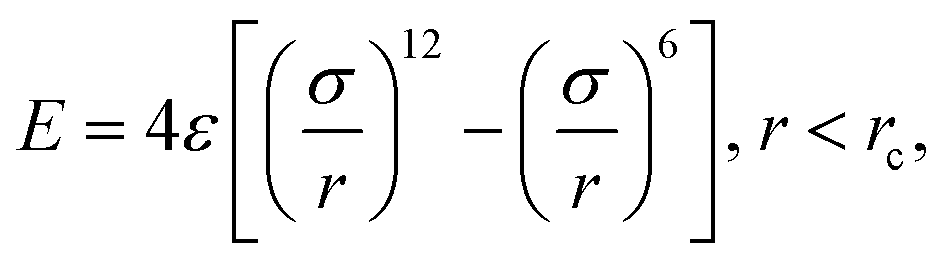 | (1) |
 . Based on Si–O–Si bond lengths, the equilibrium spacing for the potential is set to r0 = 3.28 Å, and a cutoff length rc = 10 Å. Since the main objective of this work is to show the interaction between sizing and resin, the influence of the simplification of the E-glass fibre surface is assumed to be negligible.
3.2 Reaction algorithms
Three different reaction processes are examined in this work: first, a condensation reaction in which the hydrolyzed coupling agent forms oligomers. Second, the polyurethane addition of the resin results in the B-stage material. Further, the final curing occurs by a radical polymerisation, which crosslinks the components, including the coupling agent, and thus the fibre surface. Because different reaction algorithms are used for the condensation and polymerisation reactions, they are introduced separately in the following.3.3 Condensation
To generate the condensation reaction, the Reacter framework29,30 is used. Based on pre- and post-reaction templates, this framework offers great flexibility in modeling reactions. Although it is possible to incorporate various conditions, such as an Arrhenius type condition, only a simple distance criterion is used for the condensation: if the initiator atoms are within a certain distance, a drawn random number is compared with a given probability. If the reaction takes place, the topology is updated according to the specified reaction templates. Since the main goal of this reaction is to model the formation of coupling agent oligomers from monomers, this approach is considered sufficient. In addition, Reacter allows the removal of atoms from the system during the reaction. This allows easy treatment of the water, which is a product of condensation that would otherwise have to be removed by other cumbersome techniques (such as via a diffusion-driven drying process).3.4 Polymerisation
Following Schwab and Denniston32 a more involved approach is used for both polymerisation reactions. Similar to the Reactor framework, potential reaction sites and post-reaction topology are defined based upon templates. Instead of only a simple distance criterion, an Arrhenius type equation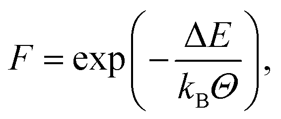 | (2) |
4 Results
As in the actual system, the manufacturing of the fibre, application of sizing, and embedding in the resin are all done in separate processes. In the following sections, the generation of the fibre–resin system is described in successive steps. The setup and conditions of each step are separately introduced, and their results are discussed:• Two rigid glass fibre surfaces, consisting of silicon atoms, representing the complex structure of a real E-glass fibre, are generated.
• The sizing layer, consisting of UPPH resin and coupling agent, is placed between these surfaces with some pre-attached γ-MPS and the condensation reaction is conducted.
• Separately, a pure UPPH resin layer is generated and compressed to an initial configuration.
• The surface–sizing layer and the resin layer are combined: the two surfaces bound the domain normal to these surfaces, followed by two sizing layers and a pure resin layer in the middle of the domain. Such a system is also schematically shown in the left of Fig. 5.
• The two-stage curing process, the polyurethane and radical polymerisation, takes place subsequently.
The Packmol48 software is used for packing of the initial molecules. In combination with Moltemplate,49 this allows a flexible setup of complex MD simulations in Lammps43,44 using force fields. A velocity-Verlet integration scheme is used to solve the Newtonian equations of motion50 is used. Temperature is adjusted by a Langevin thermostat51 and the pressure is also set, as described in the next subsection. The result is that the simulations are performed in a NPT ensemble: constant number of atoms, constant pressure, and constant temperature, although the set pressure and temperature may be different during the different steps described below, just as they would be in the actual manufacturing of a real composite system. Furthermore, simulation parameters, such as the time step and the number of time steps, for each simulation step are summarized in Table 3. In the equilibration steps, the pressure, temperature, and domain length normal to the fiber surface of the corresponding systems were observed to determine a sufficient equilibration time.
| System | Step | Time step (fs) | No. of steps |
|---|---|---|---|
| Resin | Compression | 1.0 | 200![[thin space (1/6-em)]](https://www.rsc.org/images/entities/char_2009.gif) 000 000 |
| Equilibrating | 200000 |
||
| Sizing | Compression | 1.0 | 100000 |
| Equilibrating | 200000 |
||
| Condensation | 1000000 |
||
| Combining | Compression | 1.0 | 100000 |
| Equilibrating | 200000 |
||
| Polyurethane reaction | 2 to 5 ×10⁻² | ≈5700000 |
|
| Radical polymerisation | 5 × 10⁻² | ≈5140000 |
|
4.1 Fibre surface
To create the fibre surface, a random initial distribution of Si atoms is placed in a large periodic domain, and then compressed to E-glass density. This is performed at 293.15 K with interactions based on the Lennard-Jones potential (1). For this purpose, the final density is assumed to be 2.58 g cm−3, cf. Wallenberger and Bingham.39 In addition, the silicon represents not only the mass but the entire composition of the E-glass fibres surface, see Table 2. From the final equilibrated system, two layers are extracted with a thickness of 6.56 Å, which is about twice the equilibrium bond length of a Si–O–Si bond. Thus, each layer consists of at least two Si atoms in the normal direction. The final edge length of the (square) fibre surface is 200 Å and also determines the domain sizing of the subsequent steps. In these, the silicon atoms are assumed to form a rigid layer based on the configuration created in this step. Therefore, the force on these atoms is averaged for the entire layer and an additional force representing the ambient pressure is applied. As a consequence, the pressure can be controlled while enabling the layer to move while maintaining the initial configuration of the surface atoms.4.2 Sizing layer
The implementation of the reaction algorithms (cf. Section 3) would allow depicting the complete condensation reaction of the coupling agent, including bonding to the fibre surface as well as to other coupling agent molecules, cf.Fig. 3. However, in combination with the fully atomistic approach, realistic surface coverage is not possible due to the lack of a feasible timescale. Instead, some silicon atoms of the inner surface layers have pre-attached coupling molecules before the actual condensation reaction takes place. This simplified approach seems legitimate, especially since the first chemically absorbed layer of the sizing appears to be fairly well understood11,52–54 and reasonable assumptions can be made about the spatial distribution of γ-MPS. Based on the area occupied by a coupling agent molecule on the fibre surface, reported by Miller and Ishida52 to be 0.59 nm2, a method for placing these pre-attached molecules was developed: the occupied area is converted into a mean separation distance of the γ-MPS molecules. Assuming a uniform distribution and a circular area πr2, this results in a minimum distance given by the radius r. For the first pre-attached molecule, a random atom is selected from the generated surface layer. Thereby, only the silicon atoms in the inner half of the layer are considered. Next, the Si atom with the least distance to all other pre-attached molecules is searched, keeping the minimum distance of . This atom is converted from a simple silicon atom into one with a pre-attached variant. This search for atoms with minimal but valid distance is repeated until no further pre-attached molecule can be placed. This procedure results in a certain amount of already chemically absorbed γ-MPS on the fibre surface, cf.Fig. 1.
In contrast, the main sizing layer consists of free hydrolyzed coupling agent monomers and UPPH resin acting as a film former, as they are considered to be only physically absorbed initially. The exact composition of the sizing can vary greatly in industrial applications. In this work, 30 wt% hydrolyzed γ-MPS and 70 wt% film former are assumed, which is within the range reported in the literature.3,41,55 The sizing molecules are placed between the fibre surface layers with the previously attached coupling agent molecules. The composition of the film former corresponds to the pure resin layer, and the detailed number of individual molecules of the sizing as well as the surface layer are listed in Table 2. Since the process attempts to mimic real-world processing of FRP, the condensation reaction takes place without the pure resin system, as the sizing is applied and dried during the manufacture of the glass fibre. In addition, if it is assumed that the resin is not involved in the condensation reaction, the computational effort can also be reduced. Finally, these molecules, the hydrolyzed γ-MPS and the film former, with the exception of the pre-attached γ-MPS, are again randomly positioned in a large domain and subsequently compressed to an approximated density of 1 g cm−3. This is followed by equilibration at 373.15 K with an ambient pressure of 1 atm applied via the fibre surfaces.
4.3 Condensation reaction
In the condensation reaction, the hydrolyzed γ-MPS monomers undergo a process to form oligomers. These oligomers can emerge from the physically absorbed coupling agent molecules of the sizing layer. In addition, the chemically absorbed sizing on the fibre surface, consisting of the pre-attached coupling agent molecules, also participates in the condensation process: hydrogen bonds between the hydroxyl group and the silicon atoms form covalent bonds while water is being deposited, see right in Fig. 3.The reaction is conducted starting with the configuration of the previous step, at 373.15 K and 1 atm, to take into account the conditions of the glass fibre manufacturing. Furthermore, the domain is assumed to be periodic tangentially to the fibre surface. Normal to the surface, the rigid silicon atoms limit the domain. In addition, the initial reaction probability is artificially reduced and steadily increased during the course of the condensation process. This is done to ensure a numerically stable simulation, otherwise the very high reaction speed at the beginning would lead to instabilities.
Fig. 4 shows the final distribution of the number of functional groups in the condensed sizing. Although dimer and trimer are present, the amount of higher oligomers is relative low, and most of the coupling agent is still present as a monomer. The inset in Fig. 4 illustrates the development of these groups over time. At the beginning of the simulation, despite the lower probability, the reaction exhibits a high condensation rate, thereafter the rate decreases until the end of the simulation. Although it was observed that the number of oligomers increases with time and their functionality also increases, the distribution of the coupling agent does not completely converge to a steady state (i.e. the lines in the inset of Fig. 4 are not perfectly flat at long times). Several reasons seem plausible for the high proportion of monomers in the final distribution: this can be attributed to the basic reaction algorithm, e.g. the water is removed instantly, whereas technically the water has to diffuse though the system to a free surface. As the condensation is a reversible process, these water molecules could undergo multiple reactions, influencing the final distribution of γ-MPS. Moreover, the full atomic approach used in this work does not allow for the very long timescale for such a condensation reaction in real life. A possible solution could be to omit the condensation reaction and instead work with oligomers from the beginning. However, since detailed information on the distribution of coupling agent oligomers, especially in realistic sizes, is not available in the literature, this approach would raise further issues. In contrast, a study of the condensation stage, e.g., based on a coarse-grained approach such as a united-atom model, could potentially go to longer time scales and provide detailed information about such a distribution. However, such a model would still need to be parameterised based on the fully atomistic model used here. Although such a study is highly desirable, it would be a non-trivial undertaking and is beyond the scope of this work. Moreover, it is expected that other assumptions in the introduction of the model lead to a higher uncertainty in the results. Therefore, the limitations of the presented approach for the condensation reaction are acknowledged, but the possibility to study the interaction between surface sizing and resin is nevertheless greatly extended.
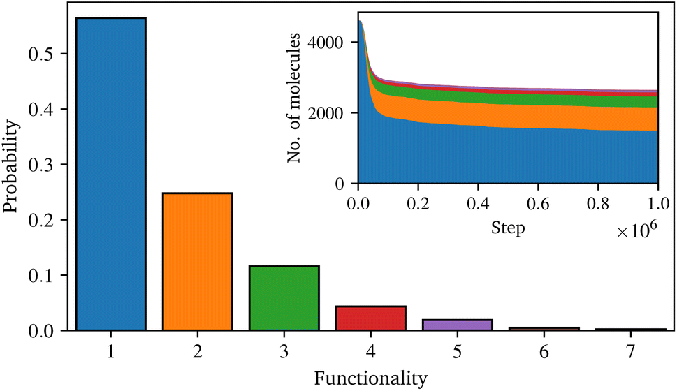 | ||
| Fig. 4 Distribution of the number of functional groups of the coupling agent after the simulation of the condensation reaction and the temporal evolution in the inset. | ||
4.4 Pure resin layer
In order to include a pure UPPH resin layer, a (separate) realistic block of resin must be created first. Therefore, the UPPH resin molecules, which are multiples of the system introduced by Schwab and Denniston,32 see Table 2, are randomly placed. As in the previous steps, the system is then compressed to an approximate density of 1.109 g cm−3 (cf. Schwab and Denniston32), and subsequently equilibrated at 293.15 K. During this process, the approach of Berendsen et al.56 is used to control the ambient pressure of 1 atm, which could be used as the domain is assumed to be periodic in all directions.4.5 Complete system
In a final step, the complete system is assembled with all three layers: first, the surface sizing system is partitioned to form the outer layers. The final sizing layer is chosen to be about 50.0 Å thick. Thus, all molecules for which the distance of their center of geometry to the fibre surfaces is below this value are extracted and form the final sizing layers. Therefore, the components of the sizing layer differ from the initial surface–sizing system described in Table 2, while approximately maintaining the relative composition. Moreover, the molecules of the resin layer are unwrapped in the normal direction, since the assumption of periodicity is no longer valid. Subsequently, the resin layer is placed between the both surface–sizing layers with a slight initial distance. This system is again compressed to an approximate density of 1 g cm−3, followed by equilibration at ambient pressure of 1 atm and 293.15 K.The system consists of two rigid layers of silicon atoms, followed by the sizing layers, with a ≈ 130 Å thick layer of resin in the centre. The resulting total domain has a base area of 200 × 200 Å and a ≈ 243 Å large extent in fibre normal direction. Based on this system, cf. left of Fig. 5, the two stage polymerisation reaction is carried out.
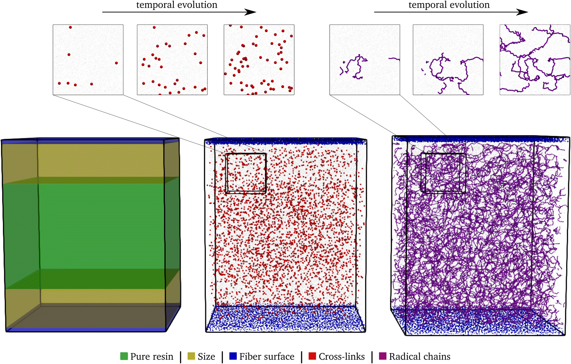 | ||
| Fig. 5 The partition of the domain in the individual layers in the left, the system after the polyurethane reaction (50% conversion rate) in the center, and after the radical reaction in the right. The individual components are highlighted in the corresponding color. In the top, sections of the domains are shown at successive time points in the reactions. | ||
4.6 Polyurethane reaction
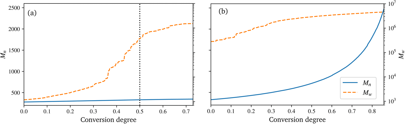
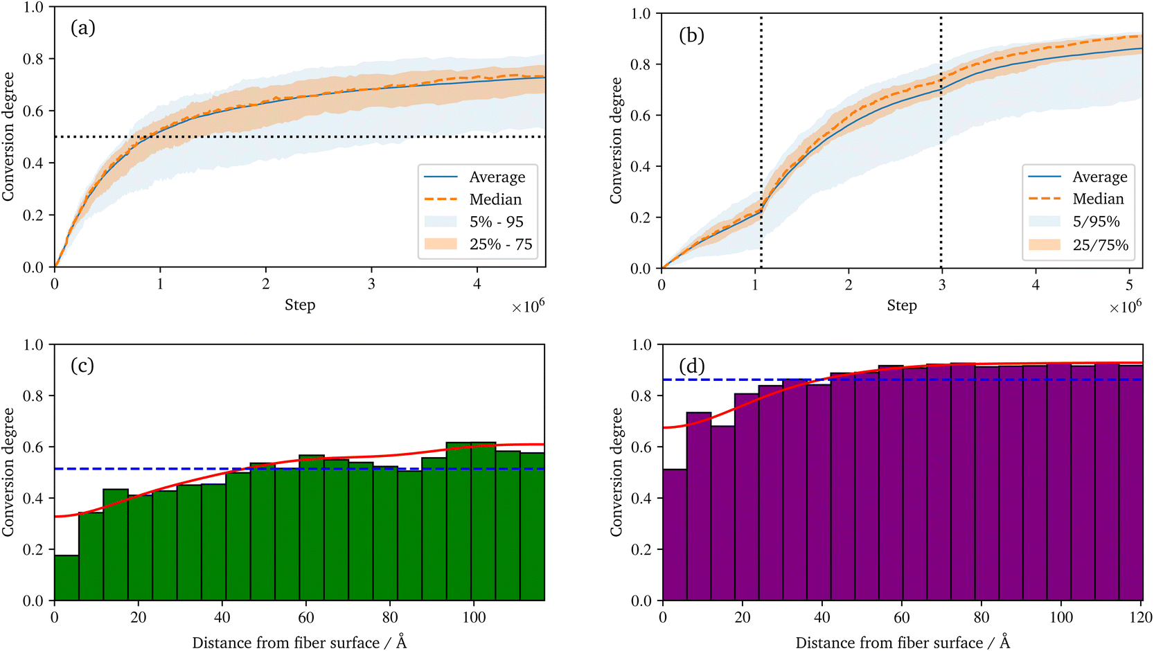
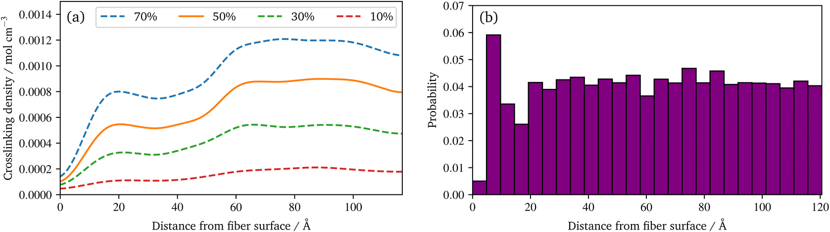
During the reaction, the unsaturated polyurethane reacts with the isocyanates groups of the (P)-MDI, resulting in a polyaddition reaction that finally yields long polyurethane molecules. This reaction is carried out at 353.15 K and ambient pressure.2 In order to speed up the simulation, ±1.5 charges are added to the initiator atoms of the reaction. As discussed by Schwab and Denniston,32 without auxiliary charges, the polymerization reaction would be too slow for the time scale used in MD simulations. Furthermore, they demonstrated the negligible influence of the charges on the results.In the centre of Fig. 5, the whole system is shown at 50% conversion. In addition, the cross-links of the isocyanates and the unsaturated polyester are highlighted, and cutouts illustrate the development over time, i.e. the increase in cross-link density. Furthermore, the reader is referred to the ESI† for a complete animation of the reaction. The evolution of the molar masses weighted by the number Mn and the molar mass Mwversus the conversion degree is shown in Fig. 6a. The detailed temporal evolution of the conversion degree over the simulation is plotted in Fig. 7a and, in addition to the average value, the median and some quantiles are also displayed. The initial fast reaction rate seems to converge quite quickly. Also, despite the average and mean values being nearly the same, it could be observed that the lowest 5% of the bins had much lower conversion degrees than the average. The domain is then binned based on the distance to the fibre surface to produce Fig. 7c which shows the spatial distribution of the binning of the conversion degree over the distance to the glass fibre surface. In addition, the average value and a Kernel Density Estimator (KDE) are displayed. The KDE is an estimate for the underlying probability density function of a random variable, and therefore provides a smooth function estimate of the distribution. The figure exhibits the highest conversion degree in the resin layer, far away from the surface. And it decreases steadily towards the glass fibre surface. Since the conversion degree relates to the number of possible reactions in each bin, a discussion of an absolute distribution is not possible. Therefore, Fig. 8a shows the spatial distribution of cross-link density, i.e. a smooth representation of the number of cross-links per volume in each bin during the reaction.
 | ||
| Fig. 6 Evolution of the number average molar mass Mn and mass average molar mass Mw for the polyurethane reaction (a) and radical polymerization (b), over the conversion degree. | ||
 | ||
| Fig. 7 Temporal evolution of the conversion degree of the polyurethane reaction (a), and the radical polymerization (b) over the simulations. The median, average, as well as percentiles of the underlying spatial binning are displayed. And the spatial distribution of the conversion degree of the polyurethane (c) and radical polymerization (d) at the end of the simulation. In addition to the histograms, the average and a smooth representation of the data (KDE) are displayed. | ||
 | ||
| Fig. 8 (a) Spatial distribution of the crosslinking density of the polyurethane reaction at different conversion degrees based on a smooth representation of the data (KDE). (b) Spatial distribution of the relative frequency of radical chains at the end of the radical polymerization. | ||
In the technical SMC process, the B-stage material represents only a semi-finished product, which can also be assumed to be not fully cured. In this work, a conversion degree of 50% of the PU reaction is assumed as starting point for the radical reaction. Especially since the definition of the conversion degree can vary: in this work, the number of actual reactions relative to the theoretical number of possible reactions is used. In contrast, an experimentally determined degree of conversion may differ, since the total number of possible reactions is generally unknown. In Fig. 6a a drastic increase of Mw at around 30 to 40% conversion can be observed. This jump over orders of magnitude indicates the phase-like transition from liquid resin to rubbery B-stage material. As the maturing of B-stage is optional,2 the assumed conversion degree of 50% as a basis for radical polymerisation is in the range of higher Mw and is considered a reasonable choice. A variation of this choice in combination with the investigation of the influence on final properties is high desirable, but beyond the scope of this work.
Regarding the crosslinking density, cf.Fig. 8a, clearly different regimes can be identified for the sizing and resin layers during polymerization. This is most likely due to the fact that the coupling agent in the sizing layer dilutes the UPPH resin of the sizing and thus, the final density of (P-)MDI is reduced. Moreover, near the fibre, the amount of γ-MPS is high due to the pre-attached coupling agent, therefore the conversion degree is the lowest, which leads also to the low conversion degree in the 5% quantile in Fig. 7a.
The spatial distribution of the benzene of the (P-)MDI and the unsaturated polyester during the polyurethane reaction is shown in the ESI.† While the distribution of the unsaturated polyester is quite smooth, the distribution of (P-)MDI is uneven. This behavior is less pronounced in the resulting crosslink density. Finally, an almost smooth transition from the resin layer to the surface and to the fiber of the conversion degree can be observed in Fig. 7c. Since the (P-)MDI consist of the largest molecules in the system, the uneven distribution most likely results from the generation of the system in combination with the limited system size. A reason why a smooth conversion degree nevertheless occurs is not evident to the authors, but could be the subject of subsequent work. However, an experimental investigation of this very thin boundary layer would be very desirable as it would allow a comparison.
4.7 Radical polymerisation
The B-staged material of the previous step is further processed in the radical polymerisation: under high temperature and pressure, the fibre-reinforced UPPH resin flows in the moulds and cures completely. Therefore, a temperature of 418 K, and a pressure of 50 bar in addition to the ambient pressure is assumed to account for the conditions in the SMC process.2 Moreover, the reaction is conducted starting with the 50% conversion configuration of the PU reaction.In the right of Fig. 5, the final system after the reaction is shown. The resulting radical chains are highlighted, and the cutouts show the evolution of these chains over time. As before, for a complete animation of the reaction, the reader is referred to the ESI.† In addition, the evolution of the molecular weights are shown in Fig. 6b. For the molecular weight Mw there is no sharp increase during the reaction, since there is no phase transition, compared to the PU reaction. Rather a smooth transition from rubbery to solid during the flow in the mould can be observed. In contrast, Mn exhibits a strongly nonlinear increase when styrene monomers, initially high in number but low in molecular weight, forms chains during polymerisation.
For the visualisation of the temporal evolution of the conversion degree over the simulation in Fig. 7b, the same approach as before is used. In addition, the vertical dotted lines mark an increase in the additional charges to accelerate the reaction and avoid excessive computational effort. For the start, charges of ±1.0 were chosen, which are increased by ±0.25 for each increment. Since the value of these charges has no direct physical effect other than hastening the reaction, no influence of the increase is expected if they are chosen within an acceptable range, cf. Schwab and Denniston,32 which is not exceeded in this work. Furthermore, the spatial distribution of the conversion degree is shown in Fig. 7d along with the average and a KDE, with the latter providing a smooth interpolation. Moreover, Fig. 8b displays the relative frequency of radical chains in relation to the distance to the fibre surface. Finally, the length of the radical chains and the spatial dependency, is plotted in Fig. 9 during the polymerization. The length of a chain is measured by the amount of carbon atoms between crosslinks of the radical chains with the PU. In the resin layer, the average length of the radical chains is about the same. In contrast, these chains are longer in the sizing, as the reduced amount of PU in this layer provides less possibilities for crosslinking. Moreover, at low conversion degrees, the chain length is almost uniform and only becomes longer towards the surface at the end of the reaction. In contrast, the resin layer reaches its final chain length rather early in the simulation. The γ-MPS, which may be part of the radical chain, allows these larger gaps between the PU to be bridged, but is less mobile compared to the small styrene molecules. Therefore, building these longer chains between the less present PU requires more time.
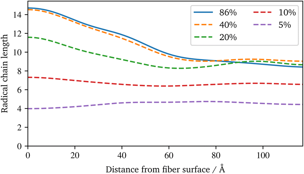 | ||
| Fig. 9 Spatial distribution of the radical chains length between PU crosslinks at different conversion degrees based on a smooth representation of the data (KDE) during the radical polymerization. | ||
It can be observed that some parts of the system have a much lower conversion degree, which distorts the displayed quantiles and also causes the difference between the average and median, in Fig. 7b. This also indicates that even with a longer simulation time, a complete conversion seem not feasible. Schwab and Denniston32 were able to archive a higher final conversion degree and could avoid the need to raise the additional charges repeatedly. However, in this work, the fibre surfaces restrict the movement of the molecules. This reduced diffusivity in the normal direction to the surface results in lower overall reactivity and thus lower conversion. Also, the typical styrene odour of the final component indicates that complete conversion is not achieved in industrial applications. In addition, as before in the UP reaction, the definition of the conversion degree may differ: the conversion degree used in this work, based on the theoretical possible reactions, may overestimate an experimental determined degree of conversion. From this reduced mobility, the result is that the lowest conversion is near to the surface, and is highest in the resin layer (see Fig. 7d).
In Fig. 10, the benzene of styrene is plotted during the radical polymerization. The benzenes are distinguished into monomeric (left) and reacted variants (right). While the unreacted benzene increases abruptly at the surface and at the interface between the size and the resin layer, the reacted styrene shows a more even distribution, increasing from the surface to the pure resin layer. Figures for the distribution of all styrene benzenes, as well as for the benzenes of other constituents and the silicon of the γ-MPS, can be found in the ESI.† Together with the conversion degree (Fig. 7d) and the frequency of the radical chains (Fig. 8b), they indicate that molecules, especially small molecules such as styrene, are able to compensate for the different composition of the sizing and resin layers. So the conversion degree does not suddenly drop at the interface, rather the highly agile styrene appears to partially diffuse into the various layers, resulting in a smooth distribution of conversion.
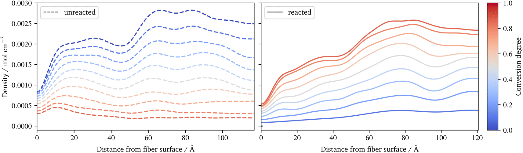 | ||
| Fig. 10 Spatial distribution of the benzene of styrene during radical polymerization. A distinction is made between monomeric, not yet reacted styrene (left) and reacted styrene in radical chains (right). | ||
In the distribution of the radical chains, cf.Fig. 8b, two things can be noted: firstly direct at the fibre surface there are almost no chains, but a high peak of chains near to the fibre can be observed. Secondly, there is an almost uniform distribution of the radical chains in the rest of the domain. The latter indicates that the presented system is able to generate a highly linked system via radical chains. This occurs despite the presence of coupling agent in the physically absorbed layer of the sizing, as the γ-MPS can take part in the radical polymerisation. While the peak close to the surface results from a layering effect of the pre-attached γ-MPS: the functionality to react with the radicals have all approximately the same distance to the fibre surface. A more detailed spatial distribution of silicon atoms of the γ-MPS during the polymerization reactions is provided in the ESI.† In addition, the quality of the crosslinking may vary locally and is moreover quite anisotropic near to the fibre surface. To illustrate these behaviours, a second animation of the racial reaction is provided in the ESI.† In this, two detail views of sections at the surface are plotted: one for which radicals create a strong connected layer at the surface, with some connection normal to the surface. In the other, no radicals diffuse near to this chemical absorbed γ-MPS layer, resulting in only a few radical chains and therefore an only loosely cross-linked surface.
5 Conclusions
Based on molecular dynamics simulations, a simplified but industrially used resin system was extended by adding a fibre surface and sizing layers. The approach of Schwab and Denniston32 was used to model the two-stage polymerisation of the UPPH resin. In addition, γ-MPS was chosen for the coupling agent, and further assumptions were made about the structure of the sizing. A systematic procedure for the development of a final cured system was presented. Based on this approach, evaluations of average quantities during the reactions were performed. Moreover, the system was also evaluated along the normal of the fibre surface, which provides a spatial analysis of the fibre–sizing–resin system.Based on the established Reacter framework, coupling agent monomers undergo a condensation reaction yielding a distribution of monomers, dimer and higher oligomers. Due to a lack of information in the literature, validation of this distribution did not seem feasible. Nevertheless, this offers an alternative approach to an arbitrarily prescribed distribution. In both the UP as well the radical reaction, a similar distribution of the final conversion degree could be observed: highest in the pure resin layer and decreasing towards the fibre, with the lowest value directly at the fibre surface. Notwithstanding, it was found that the transition between the different layers was almost smooth. This is most likely due to the diffusion of some molecules, compensating for the change in the composition of sizing and resin layers.
The introduction of the fibre surfaces reduced the diffusivity in the normal direction to the surface. This leads to a reduced overall conversion degree of the radical reaction of the final system, compared to a pure resin system. Moreover, this also results in locally varying conversion degrees and anisotropic radical polymerisation at the fibre surface. A comparison of the results of this work to experiments would be highly desirable. Although various investigations of the fibre interface were conducted9,57,58 a comparison of the results is not possible. These experiments are mainly focused on a mechanical characterisation of the interphase based on micromechanical tests. This results in effective quantities for the whole fiber–sizing–resin interface. Furthermore, these experiments clearly show that a significant part of the failure of FRP is due to the interface between fiber and resin, including the sizing. Therefore, a better understanding of the detailed processes during polymerization could also improve the design of such experiments. Nevertheless, any experiments investigating, for example, the diffusion of the sizing component during the reaction would allow a direct validation of the presented results. Moreover, this work now makes it feasible to include the mechanical testing of the final system within the MD. This is a non-trivial task, but it allows a direct comparison with the existing literature and could be the focus of a subsequent work.
In other subsequent works, the complexity of the fibre sizing can be increased: instead of only one coupling agent, several coupling agents or a different film former could be used. In addition, other additives of the sizing could be considered. Also, the basic modelling of the condensation reaction could be extended. For example, a coarse-grained approach could provide detailed insight into the behaviour of the sizing during condensation, which could enhance the full atomistic studies of the proposed approach. The assumption of the rigidity of the fibre surface could also be dropped, requiring the complex atomic structure of the fibre surface to be modelled. This could potentially improve the results, but would significantly increase the complexity. Last but not least, a further investigation of the generated system can be conducted. For example, an evaluation of the material properties of the system, e.g. the thermal or (visco-)elastic parameters, would be of great interest. In particular, an evaluation dependent on the distance to the fibre surface, as proposed in this work, would allow a deeper understanding of the sizing–resin interface. And eventually, complex properties such as a realistic interfacial fracture energy could be derived from such a system.
Conflicts of interest
There are no conflicts to declare.Acknowledgements
We thank the DFG (German Research Foundation) for funding our investigations in the framework of the International Research Training Group 2078 and NSERC (Natural Sciences and Engineering Research Council of Canada).References
- A. B. Cherian, B. T. Abraham and E. T. Thachil, J. Appl. Polym. Sci., 2006, 100, 449–456 CrossRef CAS.
- T. Böhlke, F. Henning, A. Hrymak, L. Kärger, K. A. Weidenmann and J. T. Wood, Continuous-Discontinuous Fiber-Reinforced Polymers, Carl Hanser Verlag GmbH & Co. KG, 2019 Search PubMed.
- J. Thomason, Composites, Part A, 2019, 127, 105619 CrossRef.
- E. P. Plueddemann, J. Adhes., 1970, 2, 184–201 CrossRef CAS.
- E. P. Plueddemann, Addit. Plast., 1978, 1, 123–167 CAS.
- K.L. Lowenstein, The Manufacturing Technology of Continuous Glass Fibres, Elsevier, Amsterdam, 1973 Search PubMed.
- J. Thomason, Composites, 1995, 26, 467–475 CrossRef CAS.
- J. Thomason, Composites, 1995, 26, 477–485 CrossRef CAS.
- J. L. Thomason, Composites, 1995, 26, 487–498 CrossRef CAS.
- S. L. Gao and E. Mäder, Composites, Part A, 2002, 33, 559–576 CrossRef.
- X. Liu, J. L. Thomason and F. R. Jones, J. Adhes., 2008, 84, 322–338 CrossRef CAS.
- J. Karger-Kocsis, H. Mahmood and A. Pegoretti, Prog. Mater. Sci., 2015, 73, 1–43 CrossRef CAS.
- B. J. Alder and T. E. Wainwright, J. Chem. Phys., 1957, 27, 1208–1209 CrossRef CAS.
- B. J. Alder and T. E. Wainwright, J. Chem. Phys., 1959, 31, 459–466 CrossRef CAS.
- F. H. Stillinger and A. Rahman, J. Chem. Phys., 1974, 60, 1528–1532 CrossRef.
- W. F. van Gunsteren and H. J. C. Berendsen, Angew. Chem., Int. Ed. Engl., 1990, 29, 992–1023 CrossRef.
- J. M. Barton, G. J. Buist, A. S. Deazle, I. Hamerton, B. J. Howlin and J. R. Jones, Polymer, 1994, 35, 4326–4333 CrossRef CAS.
- J. M. Barton, A. S. Deazle, I. Hamerton, B. J. Howlin and J. R. Jones, Polymer, 1997, 38, 4305–4310 CrossRef CAS.
- C. Li, E. Coons and A. Strachan, Acta Mech., 2014, 1187–1196 CrossRef.
- C. Li and A. Strachan, Polymer, 2011, 52, 2920–2928 CrossRef CAS.
- L. Gao, Q. Zhang, H. Li, S. Yu, W. Zhong, G. Sui and X. Yang, Polym. Chem., 2017, 8, 2016–2027 RSC.
- N. Sharp, C. Li, A. Strachan, D. Adams and R. B. Pipes, J. Polym. Sci., Part B: Polym. Phys., 2017, 55, 1150–1159 CrossRef CAS.
- A. C. Van Duin, S. Dasgupta, F. Lorant and W. A. Goddard, J. Phys. Chem. A, 2001, 105, 9396–9409 CrossRef CAS.
- K. D. Smith, S. I. Stoliarov, M. R. Nyden and P. R. Westmoreland, Mol. Simul., 2007, 33, 361–368 CrossRef CAS.
- M. T. Degiacomi, V. Erastova and M. R. Wilson, Comput. Phys. Commun., 2016, 202, 304–309 CrossRef CAS.
- M. E. Fortunato and C. M. Colina, SoftwareX, 2017, 6, 7–12 CrossRef.
- V. Varshney, S. S. Patnaik, A. K. Roy and B. L. Farmer, Macromolecules, 2008, 41, 6837–6842 CrossRef CAS.
- J. J. Schichtel and A. Chattopadhyay, Comput. Mater. Sci., 2020, 174, 109469 CrossRef CAS.
- J. R. Gissinger, B. D. Jensen and K. E. Wise, Polymer, 2017, 128, 211–217 CrossRef CAS PubMed.
- J. R. Gissinger, B. D. Jensen and K. E. Wise, Macromolecules, 2020, 53, 9953–9961 CrossRef CAS.
- J. J. Karnes, T. H. Weisgraber, J. S. Oakdale, M. Mettry, M. Shusteff and J. Biener, J. Phys. Chem. B, 2020, 124, 9204–9215 CrossRef CAS PubMed.
- F. K. Schwab and C. Denniston, Polym. Chem., 2019, 10, 4413–4427 RSC.
- T. Niuchi, J. Koyanagi, R. Inoue and Y. Kogo, Adv. Compos. Mater., 2017, 26, 569–581 CrossRef CAS.
- L. ho Tam, A. Zhou and C. Wu, Mater. Today Commun., 2019, 19, 495–505 CrossRef.
- S. Nouranian, C. Jang, T. E. Lacy, S. R. Gwaltney, H. Toghiani and C. U. Pittman, Carbon, 2011, 49, 3219–3232 CrossRef CAS.
- W. Jiao, C. Hou, X. Zhang and W. Liu, Compos. Interfaces, 2021, 28, 445–459 CrossRef CAS.
- M. E. Wieser, N. Holden, T. B. Coplen, J. K. Böhlke, M. Berglund, W. A. Brand, P. De Bièvre, M. Gröning, R. D. Loss, J. Meija, T. Hirata, T. Prohaska, R. Schoenberg, G. O'Connor, T. Walczyk, S. Yoneda and X. K. Zhu, Pure Appl. Chem., 2013, 85, 1047–1078 CrossRef CAS.
- U. Schubert and T. Wieder, in Silicon Chemistry, John Wiley & Sons Ltd, Weinheim, 2003, pp. 242–251 Search PubMed.
- F. T. Wallenberger and P. A. Bingham, Fiberglass and glass technology: energy-friendly compositions and applications, Springer, US, 2010, pp. 1–474 Search PubMed.
- R. Verleg and E. Hummer, COMPOSITES 2006 Convention and Trade Show, 2006, pp. 1–16 Search PubMed.
- L. Peters, Solid Mechanics and Its Applications, 2018, pp. 19–31 Search PubMed.
- E. Mäder, E. Moos and J. Karger-Kocsis, Composites, Part A, 2001, 32, 631–639 CrossRef.
- S. Plimpton, J. Comput. Phys., 1995, 117, 1–19 CrossRef CAS.
- A. P. Thompson, H. M. Aktulga, R. Berger, D. S. Bolintineanu, W. M. Brown, P. S. Crozier, P. J. in 't Veld, A. Kohlmeyer, S. G. Moore, T. D. Nguyen, R. Shan, M. J. Stevens, J. Tranchida, C. Trott and S. J. Plimpton, Comput. Phys. Commun., 2022, 271, 108171 CrossRef CAS.
- H. Sun and D. Rigby, Spectrochim. Acta, Part A, 1997, 53, 1301–1323 CrossRef.
- H. Sun, Comput. Theor. Polym. Sci., 1998, 8, 229–246 CrossRef CAS.
- H. Sun, J. Phys. Chem. B, 1998, 102, 7338–7364 CrossRef CAS.
- L. Martínez, R. Andrade, E. G. Birgin and J. M. Martínez, J. Comput. Chem., 2009, 30, 2157–2164 CrossRef.
- A. I. Jewett, D. Stelter, J. Lambert, S. M. Saladi, O. M. Roscioni, M. Ricci, L. Autin, M. Maritan, S. M. Bashusqeh, T. Keyes, R. T. Dame, J. E. Shea, G. J. Jensen and D. S. Goodsell, J. Mol. Biol., 2021, 433, 166841 CrossRef CAS.
- L. Verlet, Phys. Rev., 1967, 159, 98–103 CrossRef CAS.
- T. Schneider and E. Stoll, Phys. Rev. B: Condens. Matter Mater. Phys., 1978, 17, 1302–1322 CrossRef CAS.
- J. D. Miller and H. Ishida, Surf. Sci., 1984, 148, 601–622 CrossRef CAS.
- F. D. Blum, W. Meesiri, H. J. Kang and J. E. Gambogi, J. Adhes. Sci. Technol., 1991, 5, 479–496 CrossRef CAS.
- Q. Liu, J. Ding, D. E. Chambers, S. Debnath, S. L. Wunder and G. R. Baran, J. Biomed. Mater. Res., 2001, 57, 384–393 CrossRef CAS PubMed.
- E. Mäder, H. J. Jacobasch, K. Grundke and T. Gietzelt, Composites, Part A, 1996, 27, 907–912 CrossRef.
- H. J. Berendsen, J. P. Postma, W. F. Van Gunsteren, A. Dinola and J. R. Haak, J. Chem. Phys., 1984, 81, 3684–3690 CrossRef CAS.
- S. Zhandarov and E. Mäder, Compos. Sci. Technol., 2005, 65, 149–160 CrossRef CAS.
- S. Yan, W. Verestek, H. Zeizinger and S. Schmauder, Polymers, 2021, 13, 3085 CrossRef CAS.
Footnote |
| † Electronic supplementary information (ESI) available. See DOI: https://doi.org/10.1039/d2na00562j |
| This journal is © The Royal Society of Chemistry 2023 |