 Open Access Article
Site-specific catalysis on a micro-catalytic chip by synergistic silencing of site-directing electronic effects of functional groups in aromatics†
Rakesh
Sen
a,
Kousik
Das
 a,
Subhrokoli
Ghosh
b,
Anand Dev
Ranjan
b,
Khokan
Manna
a,
Ayan
Banerjee
a,
Subhrokoli
Ghosh
b,
Anand Dev
Ranjan
b,
Khokan
Manna
a,
Ayan
Banerjee
 *b and
Soumyajit
Roy
 *a
*a
aEFAML, Materials Science Centre, Department of Chemical Sciences, Indian Institute of Science Education and Research Kolkata, Mohanpur 741246, India. E-mail: s.roy@iiserkol.ac.in
bLight Matter Lab, Department of Physical Sciences, Indian Institute of Science Education and Research Kolkata, Mohanpur 741246, India. E-mail: ayan@iiserkol.ac.in
First published on 5th September 2023
Abstract
We report a light-driven interface engineering of a microcatalytic chip comprising a PV3W9O40 type component, MWCNTs and polypyrrole that enables unusual facile para nitration with high selectivity (95%). The chip is designed by simultaneously synthesizing the soft-oxometalate (SOM) pre-catalyst components and patterning them on a glass surface using microbubble lithography. The design reported involves interface engineering such that the exposure of the oxo-sites (of patterned SOMs) enables aromatic substrate anchoring. Such an anchoring silences the site-directing electronic effects of the functional groups in aromatics. This leads to unusual site selectivity leading to facile para-nitration with high selectivity (95%). The generality of this light driven catalyst design is demonstrated with a set of substrates that unequivocally demonstrate the silencing effect of the functional groups in aromatics. This technique can lead to an unprecedented methodology for the synthesis of any aromatic di-/tri-/multi-substitution otherwise difficult to achieve with high selectivity and atom economy, and that is sustainable in design.
1. Introduction
Sustainable synthesis of fine chemicals is a pressing challenge of our times.1,2 One of the major stumbling blocks of today's sustainable organic synthesis remains the insertion of functional groups into aromatics independent of the site directing effects of other functionals. For instance, para-nitration of nitrobenzene with a sustainable selective pathway is a case at hand.3 In this work, we take up this challenge and come up with a catalyst design as a model case study to present an option to overcome related synthetic challenges in sustainable synthetic organic chemistry. We achieve this goal by silencing the site directing electronics of the already present functional groups in the aromatics. Such silencing is achieved by an interface engineering of a precatalyst precursor (soft-oxometalate based composite)4–7 enabled by microbubble lithography (MBL).8,9 The design enables us to create an oxo interface on the catalyst chip surface, which serves as a docking site for the incumbent substrate (in this case, substituted aniline and its derivatives serve as substrates). Such docking exploits the latent electronegativities of the oxos of oxometalates and their capacity to tune the surface acidity by mobile intercalation of surface associated protons intrinsically abundant in these solid acids of the engineered catalyst interface. It is with this advantage of oxometalates in mind that we choose further supporting instruments in our catalyst design that involve and facilitate rapid electron relay to facilitate the hydrogen bonding-assisted docking of the substrate. Those supporting instruments are highly electron conducting leit motifs, multi-walled carbon nanotubes (MWCNT,) and polypyrrole (PPy).10,11 The docking design is inspired by the biomimetic catalyst design pursued in our lab.12 In the course of docking of functional groups via hydrogen bonding to the oxo-surface of the catalyst at the interface, the site-directing capacity of the docking functional groups of aromatic substrates is silenced.13 Such silencing concomitantly enables subsequent facile oxidation of the other functionalities of the aromatics that are now stereo-electronically accessible to the reactant (oxidant). The oxidation thus initiated by the reactant is now further facilitated by an oxo transfer from the engineered catalyst oxo interface by concomitant likely creation of an oxygen vacancy.14 It is to be noted that such an oxo-transfer in catalytic conversion involving oxometalates has been reported earlier in the literature by several groups.15,16 We now exploit to our advantage the created oxygen vacancy at the engineered catalyst interface to release the docked oxidized substrate by breaking the hydrogen bond and thereby perpetuating the catalytic cycle by further docking of an incumbent new substrate. It is thus our view that such a facile precatalyst design achieved by MBL with a SOM precursor can lead in principle to unusually oxidized multi-substituted aromatics which are otherwise impossible or at the most highly expensive to synthesize by conventional synthetic routes. We explore further this design strategy of catalyst interface engineering by exploring the components of the design more explicitly and in more detail (Fig. 1).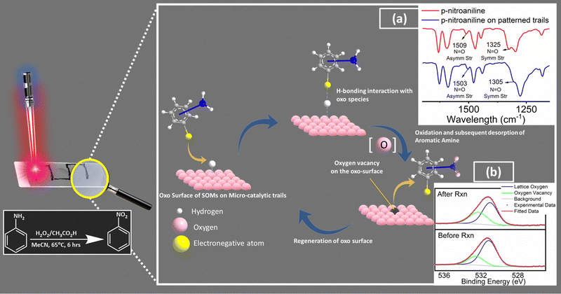 | ||
Fig. 1 Rationale of our design strategy for catalytic chip design and the tentative reaction pathway (inset: red shifts in N![[double bond, length as m-dash]](https://www.rsc.org/images/entities/char_e001.gif) O symmetric and asymmetric stretching frequencies of p-nitroaniline; (a) drop-casting on the patterned trails indicates towards possible H-bonding interaction between the electronegative terminals of the substrate molecules and the oxo surface of the patterned trails indicates towards docking of the substrate molecules on the catalytic trail surface. Further comparison between high-resolution O 1s X-ray photoelectron spectra of catalytic trail materials captured before and after reaction (b) reveals increased oxygen vacancies on the surface relative to the lattice oxygen population, which further supports our proposed tentative reaction pathway. Cf. Fig. S4, ESI†). O symmetric and asymmetric stretching frequencies of p-nitroaniline; (a) drop-casting on the patterned trails indicates towards possible H-bonding interaction between the electronegative terminals of the substrate molecules and the oxo surface of the patterned trails indicates towards docking of the substrate molecules on the catalytic trail surface. Further comparison between high-resolution O 1s X-ray photoelectron spectra of catalytic trail materials captured before and after reaction (b) reveals increased oxygen vacancies on the surface relative to the lattice oxygen population, which further supports our proposed tentative reaction pathway. Cf. Fig. S4, ESI†). | ||
One of the major components of the interface engineering thus requires a platform that can create an oxo-lattice as the substrate docking surface. To enable such creation of a crystalline interface we need a malleable soft oxo-interface. Such an interface engineering can only be achieved using soft-oxometalates (SOMs)8,17–20 as precursors to create a reactive oxometalate (OM) interface with an array of oxo-docking sites.21,22 Oxometalates (OMs) are known important catalysts because of the presence of transition metals (vanadium, molybdenum, tungsten, niobium, tantalum) in changeable oxidation states with a switchable coordination environment with unique oxo-transfer ability.23 These molecules offer a wide range of intriguing applications as catalysts in organic reactions because of their adjustable redox coupled geometry and acidic nature, excellent thermal stability, natural resistance towards oxidative decomposition, and exceptional sensitivity to light and electricity.24 Indeed, various processes involving OMs as catalysts have been adopted in industry as well (e.g. conversion of 2-butene and isobutene to their corresponding alcohols, hydration of propene, polymerization of tetrahydrofuran, etc.).24 In green oxidations with H2O2 and O2, OM-based systems are often used preferably over other traditional metal catalysts because of their oxidative and hydrolytic stability. For example, the highly efficient epoxidation of alkenes by oxometalate25 or the oxidative cleavage of alkene's C![[double bond, length as m-dash]](https://www.rsc.org/images/entities/char_e001.gif) C to carbonyl compounds e.g. styrene to benzaldehyde with (BMIm)3PMo1226 and several substituted and functionalised OMs27–29 are worth mentioning. In view of challenging alkane oxidations, OMs such as TBA4H[RuIII(H2O)SiW11O39] have been discovered to activate 2°, 3° C–H, and benzylic C–H bonds in a wide spectrum of alkanes.30 In contrast, OM-catalyzed reductive transformations are relatively less explored. Furthermore, our lab has currently explored SOM-based photocatalysts even in the oxidation coupled photoreduction of CO2 to give value-added chemicals, materials, and fuels using sunlight as the only energy input.31 Oxometalates/heteropolyacids have also gained considerable traction as attractive solid acid catalysts32 and we here exploit the acidity of these solids to our advantage in substrate docking.
C to carbonyl compounds e.g. styrene to benzaldehyde with (BMIm)3PMo1226 and several substituted and functionalised OMs27–29 are worth mentioning. In view of challenging alkane oxidations, OMs such as TBA4H[RuIII(H2O)SiW11O39] have been discovered to activate 2°, 3° C–H, and benzylic C–H bonds in a wide spectrum of alkanes.30 In contrast, OM-catalyzed reductive transformations are relatively less explored. Furthermore, our lab has currently explored SOM-based photocatalysts even in the oxidation coupled photoreduction of CO2 to give value-added chemicals, materials, and fuels using sunlight as the only energy input.31 Oxometalates/heteropolyacids have also gained considerable traction as attractive solid acid catalysts32 and we here exploit the acidity of these solids to our advantage in substrate docking.
Soft-oxometalates, the soft-matter state of oxometalates4,5 further being processible and with a malleable mobile phase and a diffuse and active interface, are easily amenable to interface engineering.6,7 We exploit this feature in embedding PPy and MWCNT in the integrated interface design. Additionally, the constituents of this phase are responsive when they are perturbed by simply modulating the polarity of the dispersing phase. These typical properties of the malleable matter interface, which is essentially soft, makes them a material of choice when interface engineering for catalyst micro-fabrication is thought of in the present context. It is in the light of the ongoing discussion that the requirements of SOMs as a platform for facile integrated interface engineering to carry out the designed reaction of unusual selectivities as in p-nitration of nitro aromatics emerges. In short, the desired interface design to carry out a reaction requires the following features. (1) A SOM–POM (soft oxometalate to polyoxometalate) switchable reactive restructuring possibility to create a catalytic interface that can provide an oxo-lattice for substrate docking. (2) The reactive restructuring cocktail of the interface in addition to having SOMs should have a conductive component like MWCNTs, pPy, etc., facilitating electronic augmentation of the catalytic reactivity when the SOM–POM reactive interface is activated by MBL. (3) The oxo-interface augments substrate anchoring and also provides a platform for the release of the substrate and creation of oxygen vacancies for further perpetuation of the catalytic oxo-interface.
It is to be noted that conducting polymers (e.g. polypyrrole, polyaniline)33,34 especially, in the context of diverse electronically relevant reactions play a key role by enhancing electronic interactions between the catalysts and interface by acting as supports35 in heterogeneous composite catalysts.36–38 Thus, performing chemical reactions in micro-fabricated “lab on a chip” systems instead of traditional reaction-wares with an engineered interface is always preferable because of the system's eco-friendly and sustainable nature related to re-use, catalyst selectivity, rapid reaction rates, easy control over reaction conditions, safety, portability, etc.18,39–41 To date, several materials like glass,42 polymers,43 ceramics,44 metals,45 zeolite,46etc. have been used to fabricate conventional micro-reactors via methods including soft lithography, nanoimprinting, micromachining, electroforming, etc.47 However such techniques are associated with costly and complex developments, complex reaction monitoring techniques and lower stabilities of microfabricated channels. Furthermore, most of these techniques first involve the fabrication of micro-channels after which catalytic materials are introduced.
It is in this context that our SOM–POM switchable reactive restructuring of an oxo-lattice catalytic interface with a conductive component facilitating opto-electronically coupled catalytic reactivity activated by MBL is unique and simple. The technique based on SOM–POM switching with microbubble lithography9 is tried and tested.8,9,17–20 We have employed such techniques with thermo-optical tweezers leading to micro-fabricated arrays of oxometalates (OMs) on a glass surface.8 We subsequently employed these arrays in site specific catalysis,17,18 simultaneous synthesis, doping, and micro-scale patterning of conductive materials20 and in construction of micro-scale bio-sensors for biologically relevant chemicals.19 We have also achieved patterning from various functional materials by applying the same technique on their SOM-composites.
This work, in turn is a culmination of our past efforts8,9,17–20 where we create a catalytic interface in situ comprising a conductive cocktail of MWCNTs (multi-walled carbon nanotubes), pPy (polypyrrole) and a SOM–POM precursor catalyst TBA6[PV3W9O40] (abbreviated here as MWCNT/PPy/POM) in a MBL activable interface engineering set up. We further proceeded to structure the interface using microbubble lithography driven by a near infrared laser of wavelength 1064 nm and thus able to 1. Dock the substrate and thereby 2. Silence the site-directing electronic effect of the present functional in the aromatic substrate. 3. Such a silencing in turn leads to unusually similar yield and nitro-selectivity in oxidation of a vast array of aromatic amines (this work has already been reported48). It is to be noted that with our restructured catalytic interfaces, we have achieved extreme high selectivity amounting to more than 95%. We now describe the results of the restructuring technique, and the catalytic process in detail to drive the uniqueness of this catalyst design home.
2. Results and discussion
2.1. Rationale of our design and the tentative reaction pathway
In general, the presence of electron donating/withdrawing-groups in the aromatic rings of the substrates alters the reaction energetics of organic redox processes, which is reflected in the product selectivities and yields.49,50 This leads to the need for choosing a protection/deprotection strategy in a multi-step reaction strategy.51 This increases the complexity of the synthetic scheme and increases the waste production, which ultimately results in decreased atom economy.52 Thus, a design strategy for an efficient functional catalyst which will simultaneously block such site directing functionals via non-covalent interactions (like hydrogen bonding) and favourably alter the reaction energetics is required. In this work, we create such possibilities by engineering an oxo-surface. The electron rich oxo terminals can anchor electronegative terminals of an organic substrate via hydrogen bonding interactions using surface abundant protons. This will redirect their electronic effects away from the carbon bearing the amine groups (Fig. S4, ESI†). This can be evidenced from the red shifts in the IR stretching frequencies of N![[double bond, length as m-dash]](https://www.rsc.org/images/entities/char_e001.gif) O symmetric stretching (from 1325 cm−1 to 1305 cm−1) and N
O symmetric stretching (from 1325 cm−1 to 1305 cm−1) and N![[double bond, length as m-dash]](https://www.rsc.org/images/entities/char_e001.gif) O asymmetric stretching (1509 cm−1 to 1503 cm−1) vibrations of p-nitroaniline53 upon drop-casting on the patterned trails. These shifts indicate towards possible H-bonding interaction between the nitro group of p-nitroaniline with the oxo surface of patterned trails further indicating towards docking of p-nitroaniline (substrate molecule) on the catalytic trail surface. To assist such hydrogen bonding interactions, we have also employed highly conducting leit motifs like MWCNTs and PPy, which will facilitate such interactions via facile electron relay. This makes the amine moiety stereo-electronically accessible and easy to oxidise. This hypothesis is supported by the similarity in the nitro-selectivities in the substrate scope, which is otherwise impossible to attain without silencing of the already existing functionalities in the aromatic ring. The oxidation is then facilitated via an oxo transfer from the oxo-surface of the catalytic trail generating an oxygen vacancy in the surface, which is evident in the increased oxygen vacancies on the trail surface relative to the lattice oxygen population in the high-resolution O 1s X-ray photoelectron spectra of the catalytic trail material captured after reaction compared to that captured before reaction (Fig. S5, ESI†). This vacancy in turn breaks the hydrogen bonding to release the product molecule and makes room for the next incumbent reactant molecules, and the catalyst cycle continues. We now briefly explore the patterning of the catalyst chip by MBL.
O asymmetric stretching (1509 cm−1 to 1503 cm−1) vibrations of p-nitroaniline53 upon drop-casting on the patterned trails. These shifts indicate towards possible H-bonding interaction between the nitro group of p-nitroaniline with the oxo surface of patterned trails further indicating towards docking of p-nitroaniline (substrate molecule) on the catalytic trail surface. To assist such hydrogen bonding interactions, we have also employed highly conducting leit motifs like MWCNTs and PPy, which will facilitate such interactions via facile electron relay. This makes the amine moiety stereo-electronically accessible and easy to oxidise. This hypothesis is supported by the similarity in the nitro-selectivities in the substrate scope, which is otherwise impossible to attain without silencing of the already existing functionalities in the aromatic ring. The oxidation is then facilitated via an oxo transfer from the oxo-surface of the catalytic trail generating an oxygen vacancy in the surface, which is evident in the increased oxygen vacancies on the trail surface relative to the lattice oxygen population in the high-resolution O 1s X-ray photoelectron spectra of the catalytic trail material captured after reaction compared to that captured before reaction (Fig. S5, ESI†). This vacancy in turn breaks the hydrogen bonding to release the product molecule and makes room for the next incumbent reactant molecules, and the catalyst cycle continues. We now briefly explore the patterning of the catalyst chip by MBL.
2.2. Light driven patterning of the catalyst chip by micro-bubble lithography (MBL)
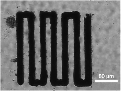
Oxometalates are great platforms for catalytic applications. Crystalline oxometalates are termed as polyoxometalates (POMs). However their colloidal soft matter formulations are termed as soft oxometalates (SOMs). In our previous studies we found that when SOMs are subjected to a thermo-optical field in an optical tweezer set-up, due to absorption of light in the wavelength of the incident laser, it undergoes phase transitions from soft colloidal SOM phase to crystalline POM phase, which is the catalytic component of our micro-catalytic trails. Thus, employing a suitable formulation of oxometalates either in its SOM regime or functional composites as a SOM–POM switchable precursor is crucial. We have previously reported the microbubble lithography-based patterning of SOMs and SOM-based composites.8,9,17,18,20 The procedure is described in detail in ref. 48 – here, we provide a brief description for completeness.In this procedure, we first place an aqueous dispersion of our sample mixture (aqueous mixture of MWCNT/PPy and POM) inside our sample chamber and irradiate it with 1064 nm laser light in an optical tweezer set up (Fig. S1, ESI†). When the focal region of the laser is incident upon some of the composite material adsorbed on a surface of the sample chamber, a water vapour bubble is formed owing to the local heating induced by the material's absorption of the laser. As there is no other heating occurring in the vicinity of the bubble, and since only the bottom surface of the bubble is in touch with the laser focal zone, the temperature throughout the bubble is not uniform, resulting in the formation of a temperature gradient. This causes a surface tension gradient on the bubble surface, which finally generates a Marangoni stress in the fluid, giving rise to a convection current in the proximity of the bubble. Due to this current, the composite material is drawn to the base of this bubble and eventually gets deposited. Now, as we move to the translation stage of the optical tweezer microscope, the focal point of the laser gets shifted – concomitantly translating the bubble, leading to self-assembly, and eventual patterning of the composite material in the wake of the bubble. Thus, by moving the translation stage in a pre-designed manner, we have obtained continuous patterns of our composite material in the micro-catalytic chip (Fig. 2).
2.3. Characterization of the patterned composite restructured interface catalyst material
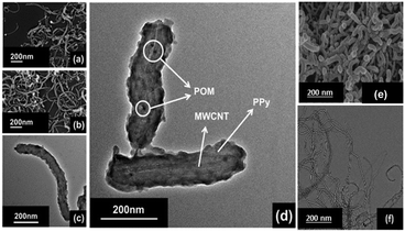 | ||
| Fig. 3 (a) and (b) SEM micrographs and (c) and (d) TEM micrographs of the patterned material, (e) SEM micrograph of the pure MWCNTs, and (f) TEM micrograph of the pure MWCNTs. | ||
The energy dispersive X-ray (EDX) study shows uniform abundance of P, V and W atoms on the surface of the composite material, which also confirms the uniform distribution of POMs (Fig. S2, ESI†).
![[double bond, length as m-dash]](https://www.rsc.org/images/entities/char_e001.gif) O (M
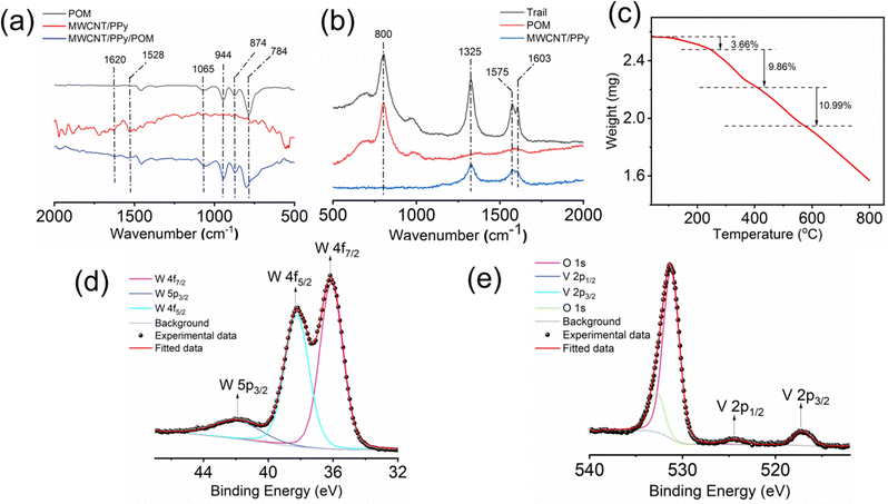
O (M![[double bond, length as m-dash]](https://www.rsc.org/images/entities/char_e001.gif) V and W, terminal oxygen), M–O–M (corner sharing oxygen) and M–O–M (edge sharing oxygen) stretching vibrations, respectively.54 In the case of the MWCNT/PPy component of the restructured interface material, the signals at around 1620 cm−1 and 1528 cm−1 can be assigned to C–N and C–C asymmetric and symmetric ring stretching, respectively, which come from polypyrrole.55 The emergence of several small peaks around 1500 cm−1 can be because of the aromatic C
V and W, terminal oxygen), M–O–M (corner sharing oxygen) and M–O–M (edge sharing oxygen) stretching vibrations, respectively.54 In the case of the MWCNT/PPy component of the restructured interface material, the signals at around 1620 cm−1 and 1528 cm−1 can be assigned to C–N and C–C asymmetric and symmetric ring stretching, respectively, which come from polypyrrole.55 The emergence of several small peaks around 1500 cm−1 can be because of the aromatic C![[double bond, length as m-dash]](https://www.rsc.org/images/entities/char_e001.gif) C stretching vibrations in the MWCNTs. All these characteristic peaks can also be found in the spectra of the MWCNT/PPy/POM composite of the restructured catalytic interface, which shows that each individual component is present in the composite of the restructured catalytic interface.
C stretching vibrations in the MWCNTs. All these characteristic peaks can also be found in the spectra of the MWCNT/PPy/POM composite of the restructured catalytic interface, which shows that each individual component is present in the composite of the restructured catalytic interface.
![[double bond, length as m-dash]](https://www.rsc.org/images/entities/char_e001.gif) C stretching in the PPy layer.
C stretching in the PPy layer.
2.4. Reaction procedure on the composite of the restructured catalytic interface and their catalytic activity
Initially, aniline was added to 5 mL of acetonitrile. Acetic acid and H2O2 were then added to the mixture. The whole mixture was shaken properly for a homogeneous solution. Then, 0.5 mL of this solution was dropcast on the composite of the restructured catalytic interface. The reaction chamber was then sealed and heated to 65 °C. The reaction mixture was kept at this temperature for 6 hours. After the completion of the reaction, the trail surface was washed with acetonitrile. The entire washing was then mixed with brine solution and extracted with ethyl acetate. The extract was then used for GC-MS analysis (Fig. 5). These micro-fabricated restructured catalytic interfaces were thus used in selective oxidation of aniline where we obtained selectivity towards the nitrobenzene.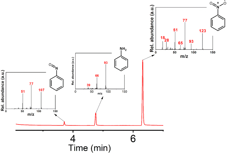 | ||
| Fig. 5 GC-MS characterization of the products. The Mass spectra of the products and reactant eluted at different times are shown in the inset figures. (Reaction conditions employed are in accordance with entry 5 of Table 1). | ||
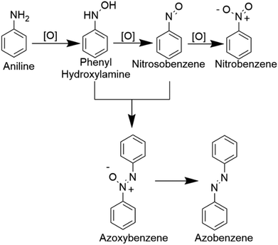
In Table 1, we demonstrate our efforts towards optimizing the selective oxidation process of aniline to nitrobenzene on our optically patterned micro-catalytic trails comprising the restructured catalytic interface. Note that, in general, the oxidation of aniline gives rise to several products (Scheme 1). In the first pass (Table 1, entry 1), we started with 6.6 mmol of aniline and 21.3 mmol of oxidant which gave us azoxybenzene as the major product. But later on, as we decreased the amount of substrate (entry 2 onwards), the product distribution displayed increasing shifts towards nitro compounds, with the overall % conversion improving significantly. Now, this may be attributed to higher substrate concentration, which favours the reaction between nitrosobenzene and phenyl hydroxylamine to give azoxybenzene.60 Furthermore, as we reduced the amount of acid employed, we clearly observed increasing selectivity towards the nitro-product. This might have been caused by the decreased amount of reactions between the nitroso and phenylhydroxylamine intermediate.
| Entry | Composition of reactant mixturea | Conversion (%) | Products selectivity (%) | ||||||
|---|---|---|---|---|---|---|---|---|---|
| Aniline (mmol) | H2O2 (mmol) | CH3COOH | CH3CN (Solvent) (mL) | Nitro | Nitroso | Azoxy | Azo | ||
| a Reactant mixture from where 0.5 mL were drop cast on micro-catalytic trails. | |||||||||
| 1 | 6.6 | 21.3 | 2.5 mL | 2.5 | 12 | 8 | 23 | 67 | 2 |
| 2 | 1.1 | 21.3 | 2.5 mL | 2.5 | 88 | 21 | 67 | 12 | — |
| 3 | 1.1 | 21.3 | 500 μL | 5 | 86 | 42 | 51 | 7 | — |
| 4 | 1.1 | 21.3 | 100 μL | 5 | 83 | 83 | 16 | 1 | — |
| 5 | 1.1 | 12.78 | 100 μL | 5 | 83 | 95 | 5 | — | — |
| 6 | 1.1 | 2.13 | 50 μL | 5 | 74 | 89 | 11 | — | — |
Then, we decreased the amount of oxidant again and reached the nitro-selectivity of 95%. Further decrease in the amount of acid and oxidant employed decreased the conversion and nitro-selectivity of the reaction. This gave us the optimized reaction conditions (entry no. 5 in Table 1).
We have also varied the temperature at which the reaction occurs and found 65 °C as the optimum operating value. Interestingly, at lower temperatures, nitrosobenzene was found to be the major product. We have also attempted p-toluenesulfonic acid and HCl as the acid components but found that in both cases the conversions and selectivity decreased. Following this, we tried several other solvents in the reaction mixture, and found acetonitrile to be ideal (Table S2, ESI†). The ratio of the individual components in the precursor cocktail has also been varied to find out their effects on the catalytic performance of the trials (Table S3, ESI†).
Lastly, we have extended our technique towards selective oxidations of 4-nitroaniline, 2-iodoaniline, 3-chloroaniline, 3,5-dimethoxyaniline, 2,6-diisopropylaniline, 2,6-dimethylaniline, 2,4,6-trimethylaniline and 2-aminophenol, and obtained selectivity in every single case towards the corresponding nitro-products. This is displayed in Fig. 6.
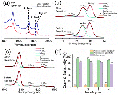 | ||
| Fig. 6 (a) Raman spectra, (b) high-resolution W 4f XPS scan and (c) high-resolution V 2p XPS scan of the micro-catalytic reactor trail recorded before and after performing the reaction. (d) Reusability of the micro-catalytic trails: % conversion and product selectivity towards nitrobenzene and nitrosobenzene over four cycles following the reaction conditions mentioned in Table 1, entry 5. | ||
2.5. Stability and reusability of the optically patterned micro-catalytic chip
To assess the stability and reusability of the micro-catalytic reactor of the restructured catalytic interface, we checked the Raman spectrographs of those trails from the restructured catalytic interface before and after performing the reaction (Fig. 7a). All of them display the characteristic peaks of the trail as mentioned before, thus proving that the chip or the restructured catalytic interface is quite stable and reusable after reaction. We have also obtained the high-resolution W 4f (Fig. 7b) and V 2p (Fig. 7c) X-ray photoelectron spectra of the trail materials after the reaction and compared them with those obtained before reaction. Both of them show the characteristic peaks at the same positions, which shows that the compositions are similar in both cases, which also establishes the stability of the optically patterned micro-catalytic chip. Furthermore, the % conversion in the reaction as well as the selectivity towards nitrobenzene and nitrosobenzene remained more or less the same up to 4 catalytic cycles, which establishes that the micro-catalytic reactors are quite reusable as well (Fig. 7d).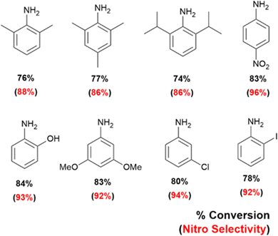 | ||
| Fig. 7 Substrate scope of selective oxidation of anilines on optically patterned micro-catalytic trails. | ||
3. Conclusion
To conclude: in this work, we have taken the exploration of site specific catalysis on a microchip to the next level and have demonstrated the power of miniaturization differently in its entirety altogether. Here we have mimicked and miniaturized an enzymatic catalysis by light driven catalyst chip design, wherein simultaneous docking and catalysing the reactants is achieved with site-specific oxidation with excellent selectivities that are otherwise impossible to achieve. Here, we have created a catalytic interface in situ comprising a conductive pre-catalyst cocktail of MWCNTs (multi-walled carbon nanotubes), pPy (polypyrrole) and a SOM–POM precursor catalyst TBA6[PV3W9O40] (abbreviated here as MWCNT/PPy/POM) in a MBL activable interface engineering set up. We have then explored its catalytic activity in the oxidation of a diverse array of aromatic amines leading to p-nitro arenes with very high selectivity (95%). The high selectivity in p-nitration suggests synergistic silencing of electronic effects of other functional moieties already present in the reactant via preferable H-bonding interaction with the oxo-surface, which also facilitates the energetics of the oxidation reaction via a facile oxo transfer, a key feature of this feat. The restructured reactive designer catalytic interface was characterised using several sophisticated characterization methods like TEM, SEM, ATR-IR, Raman, XPS and TGA studies and the reaction products were analysed with GC-MS. Additionally, the microcatalytic trails creating the restructured reactive catalytic interface with an oxo-lattice were found to be quite stable and reusable after reaction. The present work opens up, in our opinion, exciting possibilities to implement diverse catalytic applications by ‘dialling up’ an OM from a SOM in order to synthesize an output product of choice on sustainable and green “lab-on-a-chip” catalytic systems that can circumvent traditional synthetic organic chemistry challenges like that of p-nitration. It provides us with a path of silencing electronic site-directivity of functional groups in aromatics. Most importantly, microbubble lithography in conjugation with SOM-OM platforms – the technique and materials we employ to achieve our goal – has been proven as a robust methodology to create new reactive and robust interfaces in the mesoscopic scale, which will simultaneously catalyse and steer reaction selectivities, thereby eliminating the need for a protection/deprotection strategy. This interface engineering is simple and user-friendly compared to traditional micropatterning techniques.9 As we have demonstrated clearly in this work and earlier, this interface engineering opens up new possibilities in enabling stable and efficient micro-catalytic chip design. Thus, we strongly believe that further research will open up avenues for more complex SOM–POM-based lab-on-a-chip catalytic systems with further unique features. The future of SOM–POM-MBL research is extremely promising to say the least.Conflicts of interest
There are no conflicts to declare.Acknowledgements
All authors acknowledge financial support from the SERB IMPRINT grant (IMP/2018/001715) provided by the Government of India through the Ministry of Human Resource Development (MHRD) and the Department of Science and Technology (DST), as well as financial and infrastructural support through PRIS and FIRE grants from IISER Kolkata. R.S. expresses gratitude to DST for the INSPIRE fellowship.References
- J. M. Woodley, Curr. Opin. Green Sustainable Chem., 2020, 21, 22–26 CrossRef CAS
.
- Y. Hu, H. Li, Z. Li, B. Li, S. Wang, Y. Yao and C. Yu, Green Chem., 2021, 23, 8754–8794 RSC
.
- N. N. Cyrille, A. A. Idrice, M. B. Maraf, F. A. Charles, M. N. Ibrahim, M. Ríos-Gutierrez and L. R. Domingo, ChemistrySelect, 2019, 4, 13313–13319 CrossRef CAS
.
- S. Roy, J. Indian Chem. Soc., 2022, 100385 CrossRef CAS
.
- S. Roy, J. Mater. Chem. A, 2019, 7, 23241–23245 RSC
.
- S. Roy, CrystEngComm, 2014, 16, 4667–4676 RSC
.
- S. Roy, Comments Inorg. Chem., 2011, 32, 113–126 CrossRef CAS
.
- B. Roy, M. Arya, P. Thomas, J. K. Jürgschat, K. Venkata Rao, A. Banerjee, C. Malla Reddy and S. Roy, Langmuir, 2013, 29, 14733–14742 CrossRef CAS PubMed
.
- S. Ghosh, A. D. Ranjan, S. Das, R. Sen, B. Roy, S. Roy and A. Banerjee, Nano Lett., 2020, 21, 10–25 CrossRef PubMed
.
- J. Bhagwan, S. K. Hussain, B. V. Krishna and J. S. Yu, J. Alloys Compd., 2021, 856, 157874 CrossRef CAS
.
- Y. Shi, L. Peng, Y. Ding, Y. Zhao and G. Yu, Chem. Soc. Rev., 2015, 44, 6684–6696 RSC
.
- J. Lodh and S. Roy, J. Inorg. Biochem., 2022, 234, 111903 CrossRef CAS PubMed
.
- P. Carter and J. A. Wells, Science, 1987, 237, 394–399 CrossRef CAS PubMed
.
- X. An, Q. Tang, H. Lan, H. Liu and J. Qu, Appl. Catal., B, 2019, 244, 407–413 CrossRef CAS
.
- Y. Sun, J. Zheng, J. Xu, K. Yang, Z. Zhu, T. Su, H. Ge, W. Ren and H. Lü, Fuel, 2022, 315, 123226 CrossRef CAS
.
- W. Jiang, J. Xiao, L. Dong, C. Wang, H. Li, Y. Luo, W. Zhu and H. Li, ACS Sustainable Chem. Eng., 2019, 7, 15755–15761 CrossRef CAS
.
- P. Thomas, C. Pei, B. Roy, S. Ghosh, S. Das, A. Banerjee, T. Ben, S. Qiu and S. Roy, J. Mater. Chem. A, 2015, 3, 1431–1441 RSC
.
- P. Thomas, S. Ghosh and S. Roy, ChemistrySelect, 2016, 1, 805–811 CrossRef CAS
.
- P. Thomas, S. Ghosh, A. Mallick, A. Banerjee and S. Roy, Eur. J. Inorg. Chem., 2019, 469–476 CrossRef CAS
.
- S. Ghosh, S. Das, S. Paul, P. Thomas, B. Roy, P. Mitra, S. Roy and A. Banerjee, J. Mater. Chem. C, 2017, 5, 6718–6728 RSC
.
- T. J. Paul, T. N. Parac-Vogt, D. Quiñonero and R. Prabhakar, J. Phys. Chem. B, 2018, 122, 7219–7232 CrossRef CAS PubMed
.
- A. Gil and J. J. Carbó, Front. Chem., 2022, 10 Search PubMed
.
- C. L. Hill, Chem. Rev., 1998, 98, 1–2 CrossRef CAS PubMed
.
- S.-S. Wang and G.-Y. Yang, Chem. Rev., 2015, 115, 4893–4962 CrossRef CAS PubMed
.
- C. L. Hill and C. M. Prosser-McCartha, Coord. Chem. Rev., 1995, 143, 407–455 CrossRef CAS
.
- S. L. Linguito, X. Zhang, M. Padmanabhan, A. V. Biradar, T. Xu, T. J. Emge, T. Asefa and J. Li, New J. Chem., 2013, 37, 2894–2901 RSC
.
- A. Patel, J. Mater. Sci., 2017, 52, 4689–4699 CrossRef CAS
.
- T. A. Duarte, A. C. Estrada, M. M. Simões, I. C. Santos, A. M. Cavaleiro, M. G. P. Neves and J. A. Cavaleiro, Catal. Sci. Technol., 2015, 5, 351–363 RSC
.
- W. Sun and J. Hu, React. Kinet., Mech. Catal., 2016, 119, 305–318 CrossRef CAS
.
- K. Yamaguchi and N. Mizuno, New J. Chem., 2002, 26, 972–974 RSC
.
- J. Lodh, A. Mallick and S. Roy, J. Mater. Chem. A, 2018, 6, 20844–20851 RSC
.
- R. Kawahara, R. Osuga, J. N. Kondo, N. Mizuno and S. Uchida, Dalton Trans., 2017, 46, 3105–3109 RSC
.
- S. Chen, Z. Wei, X. Qi, L. Dong, Y.-G. Guo, L. Wan, Z. Shao and L. Li, J. Am. Chem. Soc., 2012, 134, 13252–13255 CrossRef CAS PubMed
.
- S. Zoladek, I. A. Rutkowska, M. Blicharska, K. Skorupska and P. J. Kulesza, J. Solid State Electrochem., 2016, 20, 1199–1208 CrossRef CAS
.
- K. B. Ghoreishi, M. A. Yarmo, N. M. Nordin and M. W. Samsudin, J. Chem., 2013, 264832 Search PubMed
.
-
H. Dai, Topics in Applied Physics, Springer, 2001, vol. 80 Search PubMed
.
- R. F. Perez, O. S. Soares, A. M. D. de Farias, M. F. R. Pereira and M. A. Fraga, Appl. Catal., B, 2018, 232, 101–107 CrossRef CAS
.
- E.-K. Lee, S.-A. Park, H. Woo, K. H. Park, D. W. Kang, H. Lim and Y.-T. Kim, J. Catal., 2017, 352, 388–393 CrossRef CAS
.
- P. Watts and S. J. Haswell, Chem. Soc. Rev., 2005, 34, 235–246 RSC
.
- B.-B. Xu, Y.-L. Zhang, S. Wei, H. Ding and H.-B. Sun, ChemCatChem, 2013, 5, 2091–2099 CrossRef CAS
.
- K. S. Elvira, X. C. Solvas and R. C. Wootton, Nat. Chem., 2013, 5, 905 CrossRef CAS PubMed
.
- A.-L. Dessimoz, L. Cavin, A. Renken and L. Kiwi-Minsker, Chem. Eng. Sci., 2008, 63, 4035–4044 CrossRef CAS
.
- D. M. Fries, T. Voitl and P. R. Von Rohr, Chem. Eng. Technol., 2008, 31, 1182–1187 CrossRef CAS
.
- R. Knitter and M. A. Liauw, Lab Chip, 2004, 4, 378–383 RSC
.
- L. D. Zarzar, B. Swartzentruber, J. C. Harper, D. R. Dunphy, C. J. Brinker, J. Aizenberg and B. Kaehr, J. Am. Chem. Soc., 2012, 134, 4007–4010 CrossRef CAS PubMed
.
- R. Dai, Z. Zheng, C. Sun, X. Li, S. Wang, X. Wu, X. An and X. Xie, Fuel, 2018, 214, 88–97 CrossRef CAS
.
- P. L. Suryawanshi, S. P. Gumfekar, B. A. Bhanvase, S. H. Sonawane and M. S. Pimplapure, Chem. Eng. Sci., 2018, 189, 431–448 CrossRef CAS
.
- India Pat., 2020.
- C. D. Smith, G. Rosocha, L. Mui and R. A. Batey, J. Org. Chem., 2010, 75, 4716–4727 CrossRef CAS PubMed
.
- J. P. Richard, J. Org. Chem., 1994, 59, 25–29 CrossRef CAS
.
- G. Sartori, R. Ballini, F. Bigi, G. Bosica, R. Maggi and P. Righi, Chem. Rev., 2004, 104, 199–250 CrossRef CAS PubMed
.
- T. Newhouse, P. S. Baran and R. W. Hoffmann, Chem. Soc. Rev., 2009, 38, 3010–3021 RSC
.
- R. Friedel, J. Phys. Chem., 1958, 62, 1341–1342 CrossRef CAS
.
- I. Kawafune and G.-e Matsubayashi, Bull. Chem. Soc. Jpn., 1996, 69, 359–365 CrossRef CAS
.
- A. Imani, G. Farzi and A. Ltaief, Int. Nano Lett., 2013, 3, 1–8 CrossRef CAS
.
- A. Galembeck and O. Alves, J. Mater. Sci., 2002, 37, 1923–1927 CrossRef CAS
.
- V. Duc Chinh, G. Speranza, C. Migliaresi, N. Van Chuc, V. Minh Tan and N.-T. Phuong, Sci. Rep., 2019, 9, 1–9 CrossRef CAS PubMed
.
- O. Bouvard, A. Krammer and A. Schüler, Surf. Interface Anal., 2016, 48, 660–663 CrossRef CAS
.
- L. Wang, X. Gu, Y. Zhao, M. Wei, Y. Qiang and Y. Zhao, J. Mater. Sci.: Mater. Electron., 2018, 29, 19278–19286 CrossRef CAS
.
- R. Meenakshi, K. Shakeela, S. K. Rani and G. R. Rao, Catal. Lett., 2018, 148, 246–257 CrossRef CAS
.
Footnote |
| † Electronic supplementary information (ESI) available. See DOI: https://doi.org/10.1039/d3ma00339f |
| This journal is © The Royal Society of Chemistry 2023 |

