 Open Access Article
Dendritic hollow nitrogen-doped carbon nanospheres for oxygen reduction at primary zinc–air batteries†
J.
Anjana
 ,
Anook Nazer
Eledath
and
Azhagumuthu
Muthukrishnan
 *
*
School of Chemistry, Indian Institute of Science Education and Research Thiruvananthapuram, Maruthamala P.O., Vithura 695551, Kerala, India. E-mail: muthukrishnan@iisertvm.ac.in
First published on 18th August 2023
Abstract
The cost and scarcity of platinum-based electrocatalysts are the major drawbacks for the large-scale commercialization of low-temperature fuel cells. Transition metal or metal-free heteroatom-doped carbon catalysts are promising alternative electrocatalysts for the oxygen reduction reaction in alkaline fuel cells. Dendritic hollow N-doped carbon spheres with a large inner accessible surface area are synthesized from the polyindole precursor on a dendritic fibrous nano-silica template. The thus-synthesized metal-free N-doped carbon material exhibits the highest onset (∼1.0 V vs. RHE) and half-wave potential (0.84 V vs. RHE), surpassing the ORR activity of the state-of-the-art Pt/C catalysts. The pore size plays an important role in the activity and in controlling the reaction pathway, wherein mesopores catalyze the partial reduction of O2 to H2O2, and micropores facilitate the H2O2 reduction to H2O. A zinc–air battery using the synthesised catalyst as the ORR catalyst exhibits the highest power density of 175 mW cm−2 with excellent specific capacity (951 mA h gzn−1 @ 20 mA cm−2), depending on the surfactant used and synthesis method. The ORR mechanism on the dendritic hollow N-doped carbon, based on the synthesis method and surfactants, is discussed.
Introduction
After the inception of cobalt phthalocyanine and heat-treated macrocyclic compounds as oxygen reduction reaction (ORR) electrocatalysts,1,2 numerous developments were made, particularly on the metal-incorporated nitrogen-doped carbon (M–N/C type) materials to replace the expensive platinum-based catalyst.3–11 Subsequently, metal-free heteroatom-doped carbon materials were developed for the ORR, which exhibit higher activity and durability in alkaline medium.12–16 Materials synthesis plays an important role in achieving a desirable ORR activity for metal-free catalysts. In particular, the focus is on synthesizing materials with higher surface area, porosity, and conductivity. Nanoparticles with a porous carbon surface possessing a larger surface area increase the mass transport kinetics, and the pore size plays a vital role in the catalytic activity and mechanism of the ORR. Mesoporous materials are well-known candidates for the production of H2O2 by 2-electron reduction of oxygen,17,18 whereas recent reports indicate that the micropores activate the H2O2 reduction to H2O.19,20Template-assisted synthesis is a promising method to achieve higher-surface area carbon materials with a tunable pore size.20–26 Porous silica materials are popularly known templates owing to their facile synthetic methods and the ease of removing the template after use. Dendritic fibrous silica nanoparticles (KCC-1)27 are used as templates for synthesising high surface area carbon materials with facile internal surface accessibility. The carbon-based materials synthesized using templates were used for applications in catalysis, gas adsorption, solar energy harvesting, etc.28 Nano-casting of silica dendritic nanomaterials to prepare porous carbon materials with a desired pore size is an interesting method to synthesize carbon-based electrocatalysts for the ORR. Nanostructured carbon-based electrodes act as the most promising air cathodes in zinc–air batteries (ZABs) due to their high ORR and OER bifunctional activity, large surface area, porous structures, and superior durability.29 Many carbon materials doped with heteroatoms and/or metal nanoparticles have been extensively studied as exciting candidates for air cathode materials in ZABs.30 Also, the carbon structures tuned by introducing functional groups and heteroatoms significantly enhance the battery performance, and M–N/C catalysts have been found to be one of the most promising candidates.31
Polyaniline (PANI) and polypyrrole (PPy) are the most common and efficient N-containing polymer precursors to synthesize N-doped carbon catalysts for the ORR. The morphology and porosity of carbon materials can be tuned using soft and/or hard templates.20–22,24,32 Vapour-phase polymerization of N-containing monomers on silica templates is a method used to achieve uniform thin layer nanocasting for N-doped carbon materials. Beyond PANI and PPy, polyindole (PIn) offers additional advantages, such as high thermal stability and less toxicity, and is used as a precursor for the synthesis of N-doped carbon materials for the ORR.33–36
In this work, dendritic hollow N-doped carbon (DHNC) materials were synthesised using polyindole on a dendritic silica template. The improved mass transfer kinetics due to accessible inner space (hollow) and the highest onset potential demonstrate that DHNC is a promising alternative to the commercial Pt/C catalyst in an alkaline fuel cell cathode. The pore size of DHNC was controlled by choosing appropriate synthetic methods and surfactants for the template, wherein the nature of the pores controls the mechanism of the ORR. The importance of different pore sizes in the mechanistic pathway was outlined. The DHNC materials coated on carbon paper, due to their highly porous nature and commendable ORR performance, are used as air-cathode catalysts in a homemade zinc–air battery setup to deliver a high power density (175 mW cm−2) and specific capacity (951 mA h gzn−1 @ 20 mA cm−2), making them a potential candidate in practical applications.
Experimental methods
Synthesis of PIn@c-SiO2-900
The PIn@c-SiO2-900 was synthesized using commercially available mesoporous colloidal silica (Ludox 40). Polyindole was synthesized on colloidal-SiO2 (c-SiO2, 0.2 M) using 0.1 M FeCl3 as an oxidizing agent. The polyindole and c-SiO2 composite was separated by centrifugation, washed with water, and heated to 900 °C under a N2-atmosphere for an hour. After removing the silica template using NH4HF2, the carbon materials were heated again to 900 °C (N2 atmosphere) for an hour to obtain PIn@c-SiO2-900.Synthesis of PIn@CTAB-900 and PIn@CPB-900
The synthesis of DHNC nanospheres is described schematically in Fig. 1. It consists of two stages: (1) preparation of the template and (2) synthesis of DHNC. First, the dendritic fibrous nano-silica (DFNS) template was synthesized using a previously reported procedure by Polshettiwar et al.27 Briefly, 2.7 ml of tetraethyl orthosilicate (TEOS) in 1.5 ml 1-pentanol and 30 ml cyclohexane was added dropwise to an aqueous solution of 1 g cetyltrimethylammonium bromide (CTAB) or cetyl pyridinium bromide (CPB) with 0.6 g urea in 30 ml H2O, followed by stirring, and the mixture was transferred into a Teflon-lined stainless steel autoclave and heated to 120 °C for 24 h. The residue is washed with water and ethyl acetate and dried under vacuum. Finally, it was heated at 600 °C for one hour in the air to obtain the DFNS silica template. Subsequently, indole (0.1 M) was polymerized using FeCl3 as the oxidant on the DFNS template, and the polymer–silica composite was heated at 900 °C under a N2-atmosphere for an hour followed by the removal of the template using NH4HF2. Finally, the carbon materials were heated to 900 °C (N2 atmosphere) for an hour to obtain PIn@CTAB-900 or PIn@CPB-900. The PIn@CTAB-900MW and PIn@CPB-900MW were synthesised using a similar methodology described above, with the exception that the microemulsion of cyclohexane (TEOS and 1-pentanol) in water (CTAB and urea) was subjected to microwave treatment at 400 W power and 120 °C for two hours to synthesize DFNS in the template synthesis.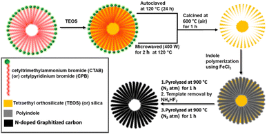 | ||
| Fig. 1 Schematic diagram of dendritic hollow N-doped carbon material synthesis using CTAB or CPB surfactants and TEOS templates from polyindole precursors. | ||
Electrochemical analysis
The electrochemical experiments of the DHNC materials were performed using a PARSTAT multichannel potentiostat in a custom-made four-neck electrochemical cell (200 ml). As described in our previous work, the hydrodynamic linear sweep voltammetry technique was employed to study the ORR activity.37,38 This experimental procedure consists of three steps: (1) preparation of the catalytic ink, (2) coating, and (3) electrochemical studies. With 5.7 mg of the catalysts, isopropanol (150 μl) and 5 wt% Nafion® solution (25 μl) were mixed uniformly using sonication. The desired volume of the catalytic ink was coated on the glassy carbon disk electrode of the RRDE with a loading density of 400 μg cm−2. The catalyst-modified GC disk, Ag/AgCl (sat. KCl), and platinum mesh in a glass tube separated using glass frit were used as working, reference, and counter electrodes, respectively. The platinum ring electrode around the GC disk (with a theoretical collection efficiency of 0.37) was used to determine the quantitative amount of H2O2 from the disk using chronoamperometry. Based on the ring, disk currents, and collection efficiency, one can calculate the number of electrons (n) and percentage of H2O2, as shown below:where Id, Ir, and N represent the disk current, ring current and collection efficiency. The accelerated durability test (ADT) proposed by DoE (USA) was used to study the stability of the catalysts. The protocol included scanning the electrode from 1 V (ORR off) to 0.6 V (ORR on) at a scan rate of 50 mV s−1 in an O2-saturated 0.1 M KOH electrolyte for several cycles. Here, the catalyst-modified rotating disk electrode (RDE) (5 mm diameter) with the same loading density was used, and the experiment was carried out for 10
![[thin space (1/6-em)]](https://www.rsc.org/images/entities/char_2009.gif) 000 cycles (44.4 hours). A zinc–air battery was constructed to check the performance of the catalysts. The catalysts were coated on a carbon gas diffusion electrode with a loading density of 1 mg cm−2. The zinc plate (0.5 mm thickness) and catalysts-coated carbon paper were used as an anode and cathode, respectively. In a homemade zinc–air battery setup, the anodes and cathodes were separated by a distance of 1.5 cm, and the cell was filled with the 6 M KOH + 0.2 M zinc acetate electrolyte. The discharge polarization experiment was performed by applying various current densities starting from 0 (open circuit potential) to 300 mA cm−2.
000 cycles (44.4 hours). A zinc–air battery was constructed to check the performance of the catalysts. The catalysts were coated on a carbon gas diffusion electrode with a loading density of 1 mg cm−2. The zinc plate (0.5 mm thickness) and catalysts-coated carbon paper were used as an anode and cathode, respectively. In a homemade zinc–air battery setup, the anodes and cathodes were separated by a distance of 1.5 cm, and the cell was filled with the 6 M KOH + 0.2 M zinc acetate electrolyte. The discharge polarization experiment was performed by applying various current densities starting from 0 (open circuit potential) to 300 mA cm−2.
Results and discussion
Characterisation
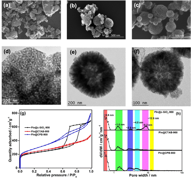
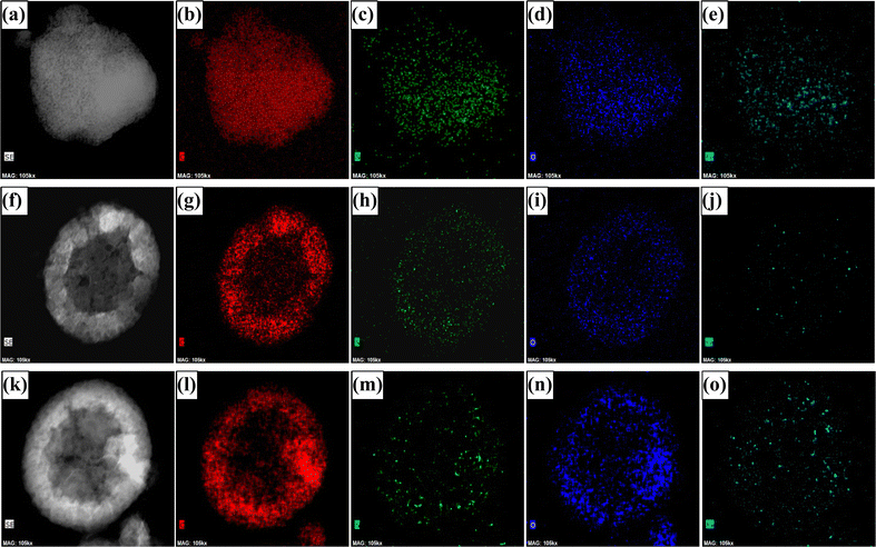
The powder X-ray diffraction (PXRD) patterns demonstrate broad peaks at 2θ = 11.6°, 25.4°, and 43.6°, indicating 001, 002, and 100 planes of graphitised carbon, respectively (Fig. S1, ESI†). The degree of graphitisation can be seen from the typical D and G bands of the Raman spectra (Fig. S2, ESI†). The value of ID/IG lies between 1.12 and 1.24, indicating a reasonable defect density in the carbon materials. The generation of defects can be rationalized by the introduction of heteroatoms and the porous nature of the materials. The X-ray photoelectron spectra (XPS) demonstrate that the materials consist of carbon, nitrogen, and oxygen elements (Fig. S3, ESI†), where the atomic weight percentage of nitrogen is approximately 2% (see ESI†). The N-1s XPS spectrum was deconvoluted into four peaks, assigned to pyridinic nitrogen (397.7 eV), pyrrolic nitrogen (398.9 eV), graphitic nitrogen (400.5 eV), and nitrogen oxides (402.2 eV), as shown in Fig. 2. The pyridinic and graphitic nitrogen components constitute the major portion (more than 70%) of the nitrogen content (Fig. 2 and Table S1, ESI†). The XPS spectra showed no traces of Fe in the DHNC materials.The morphology of carbon materials was analysed using scanning electron microscopy (SEM) images. The SEM images show porous, dendritic spherical structures of PIn@CTAB-900 and PIn@CPB-900 (Fig. 3(b) and (c)). Besides, broken spherical and doughnut-shaped morphology was seen, perhaps formed during the removal of the template under harsh conditions. Polyindole formed outside of silica templates leads to the formation of a graphite layer or sheet-like morphology, also seen in the SEM images. Hence, the compounds comprise composite dendritic porous N-doped carbon spheres connected with the graphitic layers. The material synthesised using CPB shows more definite structures than the material synthesised using CTAB. However, the N-doped carbon materials synthesised using the colloidal SiO2 template (Fig. 3(a)) show a bulk flake-like morphology similar to that of bulk phase polymerisation (Fig. S6, ESI†). Further analysis using transmission electron microscopy (TEM) reveals the hollow nature of porous dendritic spheres where the center hollow portion can be accessed via the channels, connecting the inner space with the surface. These channels are visible in the TEM images (Fig. 3(e) and (f)). The DHNC has an average diameter of ∼300 nm, wherein more than half of the volume is hollow. The TEM images of PIn@c-SiO2-900 (Fig. 3(d)) indicate that the bulk flakes consist of uniform-sized, equally spaced ordered mesopores. The high-angle annular dark-field scanning transmission electron microscopy (HAADF-STEM) images and electron energy loss spectroscopic (EELS) elemental mapping exhibit the uniform distribution of nitrogen and oxygen in the particles (Fig. 4). Interestingly, traces of iron species were found. Conversely, no Fe particles or other Fe compounds were seen from XPS data. The porous morphology of these materials' and their role in the ORR are intriguing.
The surface area and nature of the pores present in the N-doped carbon materials were examined through the N2-sorption study using the Brunauer–Emmett–Teller (BET) adsorption isotherm. All materials show a type IV adsorption isotherm with a hysteresis loop observed above P/P0 = 0.45 (Fig. 3(g)). The PIn@CTAB-900 and PIn@CPB-900 exhibit an H4-type hysteresis loop. The BET surface areas are estimated from the isotherms satisfying the Rouquerol condition39 and are found to be 850.7 and 955.2 m2 g−1 for PIn@CTAB-900 and PIn@CPB-900, respectively. The higher surface area can be rationalized by considering the accessible inner space of the materials (Table S2, ESI†).
Despite having a significantly high surface area with similar morphology from SEM and TEM images, the pore size distribution (PSD) depends on the synthetic methods. The PSD studies conducted using non-local density functional theoretical (NLDFT) modelling (Fig. 3(h)) indicate that the PIn@CTAB-900 material possesses a considerable amount of microporosity (SmicroA = 398.3 m2 g−1). Conversely, PIn@CPB-900 shows a significant contribution from mesopores, with micropores contributing less to the surface area (SmicroA = 184.4 m2 g−1). PIn@c-SiO2-900 exhibits a type IV isotherm, wherein the hysteresis loop indicates the narrow range of well-defined, uniform mesopores (H1 type), as seen from the TEM image in Fig. 3(d). Although PIn@c-SiO2-900 consists of well-defined mesopores, the significant micropores also contribute to the total surface area of 786.8 m2 g−1. A comparatively lower surface area was observed for the polyindole synthesized without any template (Fig. S8, ESI†). The surface area of PIn-900 was estimated to be 93.5 m2 g−1, indicating the importance of template synthesis to increase the surface area of carbon materials.
Rotating ring-disk electrode voltammetry
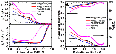
The hydrodynamic linear sweep voltammograms of the ORR on the DHNC catalysts are shown in Fig. 5(a). Among these carbon materials, PIn@CTAB-900 shows the highest ORR activity with an onset potential (Eonset) of 0.99 V, followed by PIn@CPB-900 (Eonset = 0.97 V). The porosity of the materials has ameliorated the mass-transfer kinetics, dictated by higher half-wave potentials for CTAB (E1/2 = 0.84 V) and CPB (E1/2 = 0.83 V) surfactant-based DHNC materials, which are comparable to those of the recently reported Fe–N/C catalysts for their best ORR activity (Table 1). The improved mass transport is primarily attributed to the hollow porous nanosphere morphology and high surface area. The PIn@c-SiO2-900 shows an Eonset close to 1.0 V, equivalent to that of the state-of-the-art Pt/C catalyst, perhaps due to the uniform narrow mesopore distribution in PIn@c-SiO2-900. All three compounds exhibit a 4e− reduction (n ≈ 3.86 at 0.5 V), as shown in Fig. 5(b). However, the conventional bulk phase polymerisation of polyindole (PIn-900) exhibits a less positive Eonset (0.87 V) and E1/2 (0.65 V). The improved ORR activity of the N-doped carbon materials synthesised using templates can be rationalized by the pores generated by the templates, leading to a subsequent increase (three to four-fold) in the surface area due to the pores. The RRDE voltammograms at different rotational speeds are given in Fig. S9 (ESI†).| Precursors | Synthetic conditions | E onset (V vs. RHE) | E 1/2 (V vs. RHE) | Number of electrons (n) | Shift in E1/2 in mV (no. of stability cycles) | Ref. no. |
|---|---|---|---|---|---|---|
| HT – heat treatment; MW – microwave-assisted | ||||||
| 1,3-Dicyanobenzene + Fe(OCH3)2 | HT-900 °C | 0.93 | 0.77 | 3.7 | 33 (5000) | 40 |
| 1,3-Dicyanobenzene + Fe(OCH3)2 | HT-900 °C | 0.98 | 0.87 | — | 1 (250) | 41 |
| Polypyrrole + FeCl3 | HT-900 °C | 1.02 | 0.93 | 4 | 26 (10![[thin space (1/6-em)]](https://www.rsc.org/images/entities/char_2009.gif) 000) 000) |
42 |
| 2,6-Pyridinedicarboxylic acid chloride + 3,5-diamino-1,2,4-triazole + trimethylamine + FeCl2 | Reflux | 0.86 | — | 3.8 | — | 43 |
| Ferrous gluconate + glucosamine + TEOS | HT-900 °C | 1.02 | 0.91 | ∼4 | 8 (5000) | 44 |
| MOF-74 + Fe-phenanthroline | MW-HT | 1.05 | 0.942 | ∼4 | 5 (5000) | 45 |
| Ferrocene + imidazole | HT-800 °C | 0.9 | 0.81 | 3.95 | — | 46 |
| GO + FeCl2 + melamine | HT-750 °C | 1.05 | 0.87 | 3.87 | 10 (3000) | 47 |
| PANI + FeCl3 + rGO | Metal–ligand method | 1.06 | 0.94 | 3.99 | 13 (10![[thin space (1/6-em)]](https://www.rsc.org/images/entities/char_2009.gif) 000) 000) |
48 |
| PIn@c-SiO 2 -900 | HT-900 °C | 1.00 | 0.84 | 3.86 |
44 (10![[thin space (1/6-em)]](https://www.rsc.org/images/entities/b_char_2009.gif) 000) 000)
|
This work |
| PIn@CTAB-900 | HT-900 °C | 0.99 | 0.84 | 3.87 |
34 (10![[thin space (1/6-em)]](https://www.rsc.org/images/entities/b_char_2009.gif) 000) 000)
|
This work |
Importance of pore size in the ORR pathway
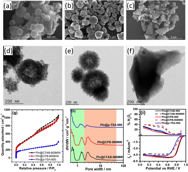
The analysis of the ORR active sites on the DHNC compounds is straightforward. It is known from previous literature that the presence of traces of Fe and nitrogen-doping (∼2 wt%) could constitute the main active sites of the DHNC. Besides, the ORR activity (to some extent) and mechanism also depend on the N-doped carbon materials’ surface area and the nature of pores. A microwave-assisted synthesis was employed to enhance the surface area of the materials, as described in the Experimental section. These materials, referred to as PIn@CTAB-900MW and PIn@CPB-900MW, show well-defined dendritic structures as shown in SEM and TEM images (Fig. 6(a), (b), (d) and (e)). The BET isotherms and pore size distribution plots indicate that the materials are highly mesoporous (using the NLDFT method) with a higher surface area of 1331 and 1287 m2 g−1 for PIn@CTAB-900MW and PIn@CPB-900MW, respectively (Fig. 6(g) and (h)).Despite having a higher surface area, the ORR activity is not very promising compared with PIn@CTAB-900 and PIn@CPB-900, as shown in Fig. 6(i). A negative shift in Eonset and E1/2 was observed, contradicting the activity-surface area correlation assumed earlier. Besides, the number of electrons decreased to ∼3.4 (∼30% of H2O2) for the compounds synthesized using the microwave-assisted method. The negative impact on the ORR activity with the increasing surface area can be rationalized by correlating the pore size distribution (PSD) with the mechanism of the ORR. The analysis demonstrates that PIn@CTAB-900MW and PIn@CPB-900MW predominantly consist of mesopores. Pores with diameter ranging from 2.5 to 6 nm are predominant in these carbon materials. One can correlate the mechanistic pathway based on the pore size distribution. Since the microwave-assisted synthesised N-doped carbon materials (PIn@CTAB-900MW and PIn@CPB-900MW) have predominantly mesopores, facilitating the 2-electron reduction of O2 to H2O2. In contrast, micropores facilitate the complete reduction (4-electron) via the 2+2-electron pathway. The mesoporous materials are well-known for their 2-electron reduction of O2 to H2O2,19 whereas the narrow micropores (<0.7 nm) facilitate the 2-electron reduction of H2O2 (formed by the mesopores) to H2O.20,49,50 Since the microwave process produces very small portions of micropores (estimated from the t-plot), the ORR produces a higher percentage of H2O2. Furthermore, to check the role of narrow micropores for the H2O2 reduction reaction, the microporous material was synthesized using p-toluene sulfonic acid (p-TSA) as a soft template, referred to as PIn@p-TSA-900. The morphology of PIn@p-TSA-900 was analyzed using SEM and TEM images, as shown in Fig. 6(c) and (f), respectively.
The BET analysis demonstrates a type 1 isotherm (Fig. 6(g)), and the PSD exhibit that PIn@p-TSA-900 consists of predominantly micropores (Fig. 6(h)) with a surface area of 590.6 m2 g−1. Although the ORR activity is comparable to that of PIn@CTAB-900MW and PIn@CPB-900MW, the number of electrons involved is higher and closer to the value of DHNC synthesised using the autoclaved method. This indicates that the presence of microporosity facilitates the completion of the ORR via the 2+2-electron pathway by improving the H2O2 reduction activity.
Stability of the catalysts
The stability of the synthesised DHNC materials (PIn@CTAB-900 and PIn@CPB-900) and the mesoporous material (PIn@c-SiO2-900) is examined as described in Section 2.3. The RDE voltammograms before and after 10![[thin space (1/6-em)]](https://www.rsc.org/images/entities/char_2009.gif) 000 cycles are given in Fig. 7. The E1/2 and IDL values after the durability tests were taken into account to study the stability of the catalysts. A negative shift in the E1/2 value was observed for the materials PIn@c-SiO2-900 (44 mV), PIn@CTAB-900 (34 mV), and PIn@CPB-900 (37 mV) after 10
000 cycles are given in Fig. 7. The E1/2 and IDL values after the durability tests were taken into account to study the stability of the catalysts. A negative shift in the E1/2 value was observed for the materials PIn@c-SiO2-900 (44 mV), PIn@CTAB-900 (34 mV), and PIn@CPB-900 (37 mV) after 10![[thin space (1/6-em)]](https://www.rsc.org/images/entities/char_2009.gif) 000 cycles, suggesting that the DHNC materials show better catalytic stability compared to the PIn@c-SiO2-900. The decrease in the limiting current was observed to be 15.4%, 6.1%, and 6.8% for PIn@c-SiO2-900, PIn@CTAB-900, and PIn@CPB-900, respectively. The results demonstrate that the DHNC shows the highest stability, with ∼6% reduction in the limiting current even after 10
000 cycles, suggesting that the DHNC materials show better catalytic stability compared to the PIn@c-SiO2-900. The decrease in the limiting current was observed to be 15.4%, 6.1%, and 6.8% for PIn@c-SiO2-900, PIn@CTAB-900, and PIn@CPB-900, respectively. The results demonstrate that the DHNC shows the highest stability, with ∼6% reduction in the limiting current even after 10![[thin space (1/6-em)]](https://www.rsc.org/images/entities/char_2009.gif) 000 cycles, compared to the mesoporous N-doped carbon materials synthesized from commercial SiO2.
000 cycles, compared to the mesoporous N-doped carbon materials synthesized from commercial SiO2.
Zinc–air battery performance
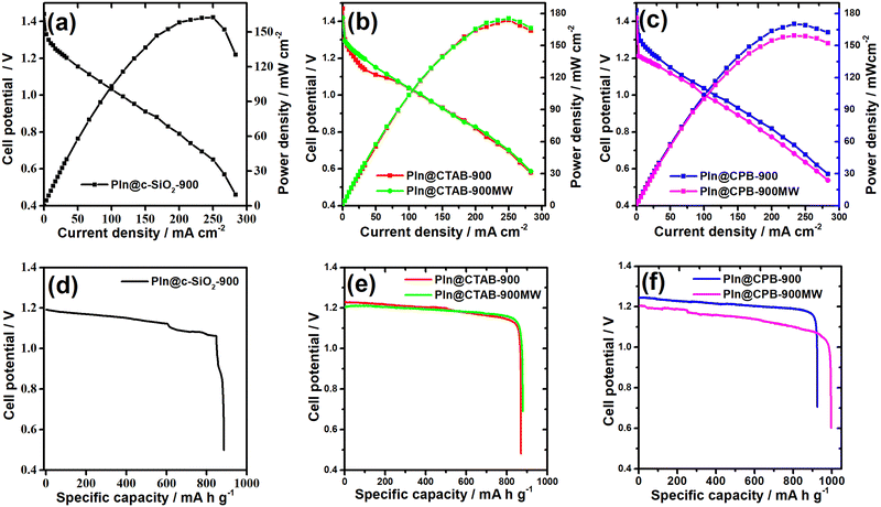
The zinc–air battery performances are shown in Fig. 8(a)–(c) for the colloidal silica template N-doped carbon and DHNC catalysts. The PIn@c-SiO2-900 coated carbon cathode exhibits an open circuit potential (OCP) of 1.44 V with a higher power density. The specific capacity of the catalysts was measured by performing the chronopotentiometry experiment with a constant current density of 20 mA cm−2. Fig. 8(d) shows the discharge-specific capacity of PIn@c-SiO2-900, which is relatively higher than that of many reported N-doped carbon materials in the literature (the values are shown in Table 2). The DHNC catalyst synthesized using the CTAB template shows an excellent power density (>170 mW cm−2), followed by the CPB template DHNC materials. The CPB templated DHNC catalysts (PIn@CPB-900 and PIn@CPB-900MW) showed excellent specific capacity (Fig. 8(e) and (f)). Especially, PIn@CPB-900MW continuously operates for more than 18 hours of discharge with a discharge current density of 20 mA cm−2, resulting in a specific capacity value of 951 mA h gZn−1. The exceptional specific capacity of DHNC catalysts can be rationalised by the larger inner surface area interconnected through the mesoporous channels. Among the previously reported Fe–N/C or metal-free catalysts, the DHNC catalysts synthesised through the CPB/TEOS template and microwave synthetic approach exhibit the highest specific capacity. A few other Fe–N/C catalysts were reported with lower power density or specific capacity values in the literature.51,52 The specific capacity of the DHNC materials is much higher than that of the recently reported materials.52–62 Besides, the performance of DHNC materials in zinc–air batteries surpasses the activity of benchmark catalysts (Pt/C) (Fig. S10, ESI†).| Compounds | OCP/V | Power density mW cm−2 | Current densitya mA cm−2 | Specific capacity mA h gZn−1 |
|---|---|---|---|---|
| a Current density at peak power density. b Loading density of Pt/C catalysts is 50 μgPt−2. | ||||
| PIn@c-SiO2-900 | 1.44 | 162.5 | 250 | 845 |
| PIn@CTAB-900 | 1.47 | 174 | 250 | 844 |
| PIn@CTAB-900MW | 1.42 | 176 | 250 | 850 |
| PIn@CPB-900 | 1.46 | 170 | 233 | 907 |
| PIn@CPB-900MW | 1.42 | 159 | 233 | 951 |
| Pt/Cb | 1.56 | 145 | 196 | 708 |
Conclusion
In conclusion, hollow dendritic N-doped carbon materials were synthesized using polyindole as a carbon and nitrogen source on dendritic silica nanospheres, followed by pyrolysis and removal of the silica template. The morphology of the DHNC material was confirmed with SEM and TEM images. Although the EELS elemental mapping shows traces of iron species, XPS and TGA confirm the negligible amount (<0.1 wt%) of iron content. Due to the accessible hollow inner space of DHNC, the mass transport kinetics of the ORR are increased. Subsequently, the hydrodynamic linear sweep voltammogram exhibits the highest ORR activity, comparable to that of the benchmark Pt/C catalysts in alkaline medium. The pore size distribution plays a vital role in the ORR activity, albeit the surface area somewhat improved the ORR activity. The combination of micropores and mesopores improves the activity rather than having either microporous or mesoporous alone, contributing to the surface area. The synergistic contribution of the mesopores (catalyse the 2-electron reduction of O2 to H2O2) and micropores (subsequent 2-electron reduction of H2O2 to H2O) ameliorates the ORR activity via the 2+2-electron pathway. The stability test indicates that the DHNC compounds exhibit higher stability with a smaller decrease in the limiting current after 10![[thin space (1/6-em)]](https://www.rsc.org/images/entities/char_2009.gif) 000 cycles. The zinc–air battery setup shows higher power density and superior specific capacity for the DHNC compounds.
000 cycles. The zinc–air battery setup shows higher power density and superior specific capacity for the DHNC compounds.
Author contributions
J. A. synthesised and performed the ORR experiments. A. N. E. performed the zinc–air battery experiments. A. M. planned, supervised and wrote the manuscript.Conflicts of interest
There are no conflicts to declare.Acknowledgements
The authors thank IISER Thiruvananthapuram for the financial support and facilities. We also thank the reviewers for their valuable suggestions to improve the manuscript.References
- R. J. Jasinski, Nature, 1964, 201, 1212–1213 CrossRef CAS.
- H. Jahnke, M. Schönborn and G. Zimmermann, in Top. Curr. Chem, ed. F. P. Schäfer, H. Gerischer, F. Willig, H. Meier, H. Jahnke, M. Schönborn and G. Zimmermann, Springer Berlin Heidelberg, Berlin, Heidelberg, 1976, vol. 61, ch. Organic dyestuffs as catalysts for fuel cells, pp. 133–181 Search PubMed.
- H. J. Lu, J. Tournet, K. Dastafkan, Y. Liu, Y. H. Ng, S. K. Karuturi, C. Zhao and Z. Y. Yin, Chem. Rev., 2021, 121, 10271–10366 CrossRef CAS PubMed.
- M. X. Chen, L. Tong and H. W. Liang, Chem. – Eur. J., 2021, 27, 145–157 CrossRef CAS PubMed.
- C. Feng, M. B. Faheem, J. Fu, Y. Xiao, C. Li and Y. Li, ACS Catal., 2020, 10, 4019–4047 CrossRef CAS.
- W. Wang, Q. Jia, S. Mukerjee and S. Chen, ACS Catal., 2019, 9, 10126–10141 CrossRef CAS.
- A. Kulkarni, S. Siahrostami, A. Patel and J. K. Nørskov, Chem. Rev., 2018, 118, 2302–2312 CrossRef CAS PubMed.
- A. A. Gewirth, J. A. Varnell and A. M. DiAscro, Chem. Rev., 2018, 118, 2313–2339 CrossRef CAS PubMed.
- Y. Han, Q. Wei, Y. Fu, D. Zhang, P. Li, X. Shan, H. Yang, X. Zhan, X. Liu and W. Yang, Small, 2023, 19, 2300683 CrossRef CAS PubMed.
- H. Fan, K. Mao, M. Liu, O. Zhuo, J. Zhao, T. Sun, Y. Jiang, X. Du, X. Zhang, Q. Wu, R. Che, L. Yang, Q. Wu, X. Wang and Z. Hu, J. Mater. Chem. A, 2018, 6, 21313–21319 RSC.
- H. Fan, Y. Wang, F. Gao, L. Yang, M. Liu, X. Du, P. Wang, L. Yang, Q. Wu, X. Wang and Z. Hu, J. Energy Chem., 2019, 34, 64–71 CrossRef.
- C. G. Hu, R. Paul, Q. B. Dai and L. M. Dai, Chem. Soc. Rev., 2021, 50, 11785–11843 RSC.
- L. Zhang, C.-Y. Lin, D. Zhang, L. Gong, Y. Zhu, Z. Zhao, Q. Xu, H. Li and Z. Xia, Adv. Mater., 2019, 31, 1805252 CrossRef PubMed.
- L. Zhang, L. Li, H. Chen and Z. Wei, Chem. – Eur. J., 2019, 26, 3973–3990 CrossRef PubMed.
- C. Hu and L. Dai, Adv. Mater., 2019, 31, 1804672 CrossRef PubMed.
- L. Dai, Y. Xue, L. Qu, H.-J. Choi and J.-B. Baek, Chem. Rev., 2015, 115, 4823–4892 CrossRef CAS PubMed.
- Y. Pang, K. Wang, H. Xie, Y. Sun, M.-M. Titirici and G.-L. Chai, ACS Catal., 2020, 10, 7434–7442 CrossRef CAS.
- T.-P. Fellinger, F. Hasché, P. Strasser and M. Antonietti, J. Am. Chem. Soc., 2012, 134, 4072–4075 CrossRef CAS PubMed.
- J. Park, Y. Nabae, T. Hayakawa and M.-A. Kakimoto, ACS Catal., 2014, 4, 3749–3754 CrossRef CAS.
- G. A. Ferrero, K. Preuss, A. B. Fuertes, M. Sevilla and M. M. Titirici, J. Mater. Chem. A, 2016, 4, 2581–2589 RSC.
- J. Jang, X. L. Li and J. H. Oh, Chem. Commun., 2004, 794–795 RSC.
- G. A. Ferrero, N. Diez, M. Sevilla and A. B. Fuertes, ACS Appl. Energy Mater., 2018, 1, 6560–6568 CrossRef CAS.
- C. Chen, J. Ma, Y. Yu, D. Xiao, Q. Luo, J. Ma, Y. Liao and X. Zuo, ChemistrySelect, 2018, 3, 5717–5725 CrossRef CAS.
- M. Shi, M. Bai and B. Li, J. Mater. Sci., 2018, 53, 9731–9741 CrossRef CAS.
- S. Q. Xiong, J. C. Fan, Y. Wang, J. Zhu, J. R. Yu and Z. M. Hu, J. Mater. Chem. A, 2017, 5, 18242–18252 RSC.
- Y. N. Liu, H. T. Wang, X. H. Kang, Y. F. Wang, S. Y. Yang and S. W. Bian, J. Power Sources, 2018, 402, 413–421 CrossRef CAS.
- V. Polshettiwar, D. Cha, X. Zhang and J. M. Basset, Angew. Chem., Int. Ed., 2010, 49, 9652–9656 CrossRef CAS PubMed.
- A. Maity and V. Polshettiwar, ChemSusChem, 2017, 10, 3866–3913 CrossRef CAS PubMed.
- W. Shao, R. Yan, M. Zhou, L. Ma, C. Roth, T. Ma, S. Cao, C. Cheng, B. Yin and S. Li, Electrochem. Energy Rev., 2023, 6, 11 CrossRef CAS.
- S. A. Samad, Z. Fang, P. Shi, J. Zhu, C. Lu, Y. Su and X. Zhuang, 2D Mater., 2023, 10, 022001 Search PubMed.
- J. Wu, B. Liu, X. Fan, J. Ding, X. Han, Y. Deng, W. Hu and C. Zhong, Carbon Energy, 2020, 2, 370–386 CrossRef CAS.
- C. Ponghiransmith, J. Y. Lin, W. Kobsiriphat, P. Limthongkul and P. Hasin, J. Alloys Compd., 2022, 898, 162773 CrossRef CAS.
- M. Warczak, M. Osial, M. Berggren and E. D. Głowacki, J. Electrochem. Soc., 2020, 167, 086502 CrossRef CAS.
- T. Sun, W. Li, M. Yang, H. Chen, Y. Liu and H. Li, J. Power Sources, 2019, 434, 226738 CrossRef CAS.
- X. Wang, M. Wang, X. Ju, Y. Zhang, J. Zhao and J. Zhang, Int. J. Electrochem. Sci., 2016, 11, 2016 Search PubMed.
- M.-T. Nguyen, B. Mecheri, A. Iannaci, A. D’Epifanio and S. Licoccia, Electrochim. Acta, 2016, 190, 388–395 CrossRef CAS.
- A. N. Eledath, A. E. Poulose and A. Muthukrishnan, ACS Appl. Nano Mater., 2022, 5, 10528–10536 CrossRef CAS.
- J. Anjana and A. Muthukrishnan, Catal. Sci. Technol., 2022, 12, 6246–6255 RSC.
- M. Thommes, K. Kaneko, A. V. Neimark, J. P. Olivier, F. Rodriguez-Reinoso, J. Rouquerol and K. S. W. Sing, Pure Appl. Chem., 2015, 87, 1051–1069 CrossRef CAS.
- Á. García, T. Haynes, M. Retuerto, P. Ferrer, L. Pascual, M. A. Peña, M. Abdel Salam, M. Mokhtar, D. Gianolio and S. Rojas, Ind. Eng. Chem. Res., 2021, 60, 18759–18769 CrossRef PubMed.
- Á. García, L. Pascual, P. Ferrer, D. Gianolio, G. Held, D. C. Grinter, M. A. Peña, M. Retuerto and S. Rojas, J. Power Sources, 2021, 490, 229487 CrossRef.
- D. Liu, J.-C. Li, Q. Shi, S. Feng, Z. Lyu, S. Ding, L. Hao, Q. Zhang, C. Wang, M. Xu, T. Li, E. Sarnello, D. Du and Y. Lin, ACS Appl. Mater. Interfaces, 2019, 11, 39820–39826 CrossRef CAS PubMed.
- L. Gu, Y. Dong, Y. Zhang, B. Wang, Q. Yuan, H. Du and J. Zhao, RSC Adv., 2020, 10, 8709–8716 RSC.
- M. Liu, L. Wang, L. Zhang, Y. Zhao, K. Chen, Y. Li, X. Yang, L. Zhao, S. Sun and J. Zhang, Small, 2022, 18, 2104934 CrossRef CAS PubMed.
- L. Peng, J. Yang, Y. Yang, F. Qian, Q. Wang, D. Sun-Waterhouse, L. Shang, T. Zhang and G. I. N. Waterhouse, Adv. Mater., 2022, 34, 2202544 CrossRef CAS PubMed.
- J.-S. M. Lee, S. Sarawutanukul, M. Sawangphruk and S. Horike, ACS Sustainable Chem. Eng., 2019, 7, 4030–4036 CrossRef CAS.
- J. He, T. Zheng, D. Wu, S. Zhang, M. Gu and Q. He, ACS Catal., 2022, 12, 1601–1613 CrossRef CAS.
- M. S. Ahmed, H. Begum and Y.-B. Kim, J. Power Sources, 2020, 451, 227733 CrossRef CAS.
- A. Gabe, R. Ruiz-Rosas, C. González-Gaitán, E. Morallón and D. Cazorla-Amorós, J. Power Sources, 2019, 412, 451–464 CrossRef CAS.
- D. Barrera, M. Florent, K. Sapag and T. J. Bandosz, ACS Appl. Energy Mater., 2019, 2, 7412–7424 CrossRef CAS.
- H.-J. Niu, S.-S. Chen, J.-J. Feng, L. Zhang and A.-J. Wang, J. Power Sources, 2020, 475, 228594 CrossRef CAS.
- B. Yuan, G. Nam, P. Li, S. Wang, X. Liu and J. Cho, Appl. Surf. Sci., 2019, 481, 498–504 CrossRef CAS.
- R. Yuan, W. Bi, T. Zhou, N. Zhang, C. A. Zhong, W. Chu, W. Yan, Q. Xu, C. Wu and Y. Xie, ACS Mater. Lett., 2020, 2, 35–41 CrossRef CAS.
- R. H. Gan, Y. L. Wang, X. W. Zhang, Y. Song, J. L. Shi and C. Ma, J. Energy Chem., 2023, 83, 602–611 CrossRef CAS.
- K. Muuli, X. Lyu, M. Mooste, M. Käärik, B. Zulevi, J. Leis, H. Yu, D. A. Cullen, A. Serov and K. Tammeveski, Electrochim. Acta, 2023, 446, 142126 CrossRef CAS.
- M. Shen, W. Hu, C. Duan, J. Li, S. Ding, L. Zhang, J. Zhu and Y. Ni, J. Colloid Interface Sci., 2023, 629, 778–785 CrossRef CAS PubMed.
- T. Yu, S. Su, Y. Che, C. Meng, H. Zhou, S. Yan, K. Patrick Ranson, T. Bian and A. Yuan, J. Electroanal. Chem., 2023, 938, 117433 CrossRef CAS.
- Y. Wang, P. Meng, Z. Yang, M. Jiang, J. Yang, H. Li, J. Zhang, B. Sun and C. Fu, Angew. Chem., Int. Ed., 2023, 62, 202304229 CrossRef PubMed.
- B. Yue, K. Yang, H. Xie, Y. Lei, J. Li and Y. Si, New J. Chem., 2023, 47, 9735–9745 RSC.
- C. Xu, C. Guo, J. Liu, B. Hu, H. Chen, G. Li, X. Xu, C. Shu, H. Li and C. Chen, Small, 2023, 19, e2207675 CrossRef PubMed.
- Q. Ye, M. Li, S. Hou, Y. Deng, J. Luo and X. Tian, Dalton Trans., 2023, 52, 2684–2692 RSC.
- B. Wang, J. Tang, X. Zhang, M. Hong, H. Yang, X. Guo, S. Xue, C. Du, Z. Liu and J. Chen, Chem. Eng. J., 2022, 437, 135295 CrossRef CAS.
Footnote |
| † Electronic supplementary information (ESI) available. See DOI: https://doi.org/10.1039/d3ma00304c |
| This journal is © The Royal Society of Chemistry 2023 |


