
 Open Access Article
 This Open Access Article is licensed under a
 Creative Commons Attribution 3.0 Unported Licence
Hydroxide conducting BAB triblock copolymers tailored for durable high-performance anion exchange membranes†
Andrit
Allushi
 ,
Pegah Mansouri
Bakvand
,
Haiyue
Gong
and
Patric
Jannasch
*
,
Pegah Mansouri
Bakvand
,
Haiyue
Gong
and
Patric
Jannasch
*
Polymer & Materials Chemistry, Department of Chemistry, Lund University, P.O. Box 124, SE-221 00, Lund, Sweden. E-mail: patric.jannasch@chem.lu.se
First published on 22nd July 2023
Abstract
Well-designed block copolymers with a controlled co-continuous microphase morphology can be applied as efficient anion exchange membranes (AEMs) for fuel cells and water electrolyzers. In the present work, we have prepared and studied a series of BAB triblock copolymers consisting of a central cationic polyfluorene A block with flanking hydrophobic polystyrene B blocks, where the fluorene units of the A block carried double pairs of piperidinium cations via flexible hexyl spacer chains. First, a polyfluorene tethered with bromohexyl chains was prepared by superacid-mediated polyhydroxyalkylation, and then modified to produce a bi-directional macroinitiator for atom transfer radical polymerization (ATRP). Next, ATRP of styrene was carried out to form BAB triblock copolymers with different lengths of the B blocks. Finally, the polyfluorene block was densely functionalized with piperidinium cations by Menshutkin reactions. Small angle X-ray scattering of block copolymer AEMs indicated the presence of both block copolymer phase domains (d ∼ 15 nm) and ionic clusters (d ∼ 6 nm). Atomic force microscopy showed clearly phase-separated morphologies with seemingly well-connected hydrophilic nanophase domains for ion transport. The AEMs reached hydroxide conductivities up to 161 mS cm−1 at 80 °C. Moreover, the AEMs decomposed only above 250 °C and possessed excellent alkaline stability with no degradation detected by 1H NMR analysis after storage in 2 M aq. NaOH, at 90 °C during 672 h. Notably, the current block copolymer AEMs showed higher alkaline stability and hydroxide conductivity compared to AEMs based on corresponding statistical copolymers.
1. Introduction
Anion exchange membrane fuel cells (AEMFCs) and water electrolyzers (AEMWEs) are environmentally friendly energy conversion and storage technologies.1–6 Operating under high alkaline conditions enables faster kinetic for the oxygen reduction reactions and opens up for the use of non-platinum group metal catalysts. Anion exchange membranes (AEMs) consist of polymers with covalently tethered cationic groups, and conduct hydroxide ions and water molecules during operation, making them a core component for AEMFCs and AEMWEs. However, in high pH media at elevated temperatures, the polymer backbone and cationic groups are normally sensitive to hydroxide attack leading to degradation and loss of performance.7–10State-of-the-art AEMs combine high ionic conductivity and excellent mechanical and chemical stability. Numerous synthetic strategies have been investigated as approaches to state-of-the-art membranes. The polymeric backbone strongly influences the mechanical properties of the AEMs. Initially, commercially available ether-containing polymer backbones, such as poly(ether ketone),11–13 poly(ether sulfone),14–16 and poly(phenyl oxide)17,18 were investigated. Although the ether bonds may enhance the solubility of the polymers, these bonds are vulnerable to OH− attack leading to polymer chain cleavage.19–22 Consequently, AEMs based on ether-free polymer backbones have been the focus of recent research in the area. Many polymerization methods, including radical polymerization, Suzuki coupling reactions, and superacid-mediated polyhydroxyalkylation reactions, have been utilized to synthesize ether-free polymers with high thermal and chemical resistance.23–32
The ion conductivity and stability of AEMs are highly related to the character and concentration of the cationic groups, and quaternary ammonium (QA) cations are the most investigated cationic groups due to their commercial availability and relatively high alkaline stability, and QAs normally provide high ionic conductivity.33–35 Still, QAs are quite sensitive towards degradation via nucleophilic substitution and Hofmann elimination reactions under strongly alkaline conditions at elevated temperatures.35,36 However, certain mono- and spirocyclic QAs show outstanding alkaline stability due to their ring structure, which raises the activation energy for the degradation reactions.37,38 Furthermore, the alkaline stability is generally highly dependent on precisely how the QAs are tethered to the polymer backbone. For example, N-alicyclic cations tethered to the polymer backbone via flexible alkyl spacers typically show high alkaline stability.39–45
Increasing the IEC, i.e., the moles of cations per gram dry membrane, is the most straightforward way to enhance the ionic conductivity of the membrane. However, increasing the IEC value is usually accompanied by high water uptake and swelling, leading to the loss of mechanical strength. Moreover, an excessive water uptake may dilute the charge carrier concentration, leading to decreased conductivity. In these cases, synthetic strategies such as covalent crosslinking and the preparation of block and graft copolymers may efficiently suppress the water uptake and swelling.46–50 Especially the combination of ionic and nonionic polymeric segments with well-tuned lengths in a block copolymer promotes the formation of a morphology with well-connected water-rich channels to control the water uptake and enhance the ionic conductivity.51–54 For example, Li and coworkers have reported on a series of ether-free polymers based on styrene and 4-fluorostyrene prepared by reversible addition fragmentation chain transfer (RAFT) polymerizations. These materials reached an ionic conductivity of 86 mS cm−1 at an IEC value 4.27 mequiv. g−1 and a water uptake of 37.5 wt% at 80 °C.55 Moreover, commercially available SEBS triblock copolymers (i.e., polystyrene-b-poly[ethylene-co-butylene]-b-polystyrene) have been modified by the introduction of QA cations onto the polystyrene end blocks.56–59 These AEMs can reach high ionic conductivity, but the soft and elastomeric poly[ethylene-co-butylene] midblock often leads to high swelling and low dimensional stability in water.56 The situation can be significantly improved by instead employing BAB triblock copolymers with a central ionic A blocks flanked by two “hard” nonionic B blocks.60
We previously synthesized statistical ether-free fluorene-based copolymers via superacid-mediated Friedel–Crafts polycondensation reactions, followed by quaternization to introduce dual pairs of piperidinium cations.45 AEMs based on these copolymers showed excellent thermal and alkaline stability. However, the AEMs suffered from a high water uptake and excessive swelling characteristics. Consequently, the present work focuses on the synthesis and characterization of BAB triblock copolymers for AEMs with a controlled morphology to improve key membrane properties. The middle (A) block was first synthesized via a polyhydroxyalkylation reaction, and was then employed as a macroinitiator for atom transfer radical polymerization (ATRP) of styrene to form the flanking polystyrene (PS) blocks. The size of the PS blocks was used to adjust and control the balance between the A and B blocks, and hence the IEC of the final AEMs. Lastly, the fluorene units of the central A block were functionalized with dual pairs of piperidinium cations. After casting AEMs, the influence of the triblock copolymer structure on the AEM morphology and on critical membrane properties such as thermal and alkaline stability, water uptake, and ionic conductivity were studied.
2. Experimental
2.1 Materials
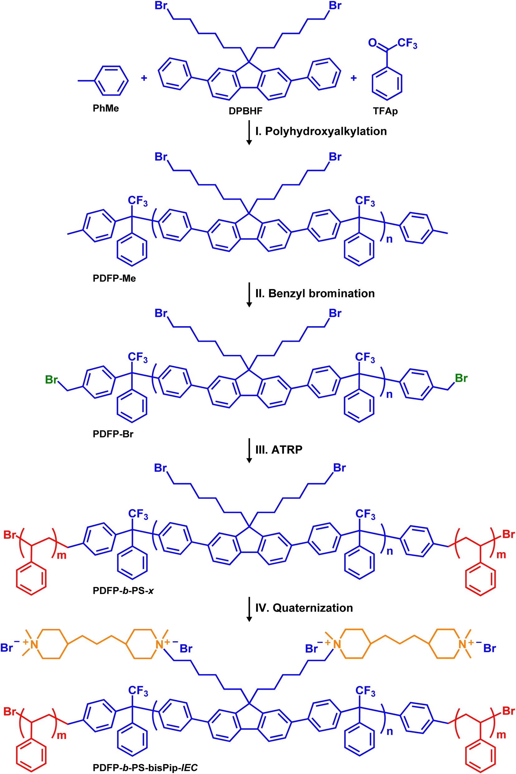
The following chemicals were used as received: 2,2′-bipyridyl (bipy, >99.0%, TCI), N-bromosuccinimide (NBS, 97%, Acros), copper powder (Cu(0) 99.5%, Sigma Aldrich), copper(I)bromide (Cu(I)Br, 98%, Sigma Aldrich), 1,2-dichlorobenzene (DCB, 99%, Thermo Scientific), 2,2,2-trifluoroacetophenone (TFAp, 99%, Sigma-Aldrich), trifilic acid (TFSA, 98%, Sigma Aldrich), methanol (analytical grade, ≥99.9%, Fisher), N,N-dimethylacetamide (DMAc, reagent plus, >99%, Sigma Aldrich), 4,4-trimethylenebis(1-methylpiperidine) (bisPip, 97%, Sigma Aldrich), azobisisobutyronitrile (AIBN, 98%, Acros), 1-methyl-2-pyrrolidinone (NMP, reagent grade, 99%, Honeywell), iodomethane (MeI, 99%, Sigma-Aldrich), 1,1,1-trifluoroacetic acid (TFA, 99%, Sigma-Aldrich), NaBr (99%, VWR), KOH (99% pellets, VWR), tetrabutylammonium bromide (TBAB, 98.0%, Sigma Aldrich), sodium carbonate (Na2CO3, 99.99%, Sigma-Aldrich), sodium nitrate (NaNO3, 99%, Sigma-Aldrich), methanol (MeOH, 99.9%, VWR), 2-propanol (IPA, 99.9%, Sigma Aldrich), silver nitrate (AgNO3, 99.995%, Sigma Aldrich), CDCl3-d (99.8 atom% D, Sigma-Aldrich), NaOH (99% pellets, Sigma Aldrich), DMSO-d6 (99.5 atom% D, Sigma-Aldrich), and diethylether (Et2O, reagent grade, Sigma-Aldrich). Dichloromethane (DCM) and toluene were dried using a MBraun dry solvent dispenser system MB-SPS 800. Additionally, the DPBHF monomer was produced following the procedure published in our previous work.612.2 Synthesis
 | ||
| Scheme 1 Pathway to BAB triblock copolymers. Key: (I) DCM, TFSA, 0 °C, (II) AIBN, NBS, DCB, 120 °C, (II) CuBr, Cu (0), bipyridine, styrene, toluene, 120 °C, (IV) bisPip, NMP, 85 °C followed by MeI, NMP, 25 °C. | ||
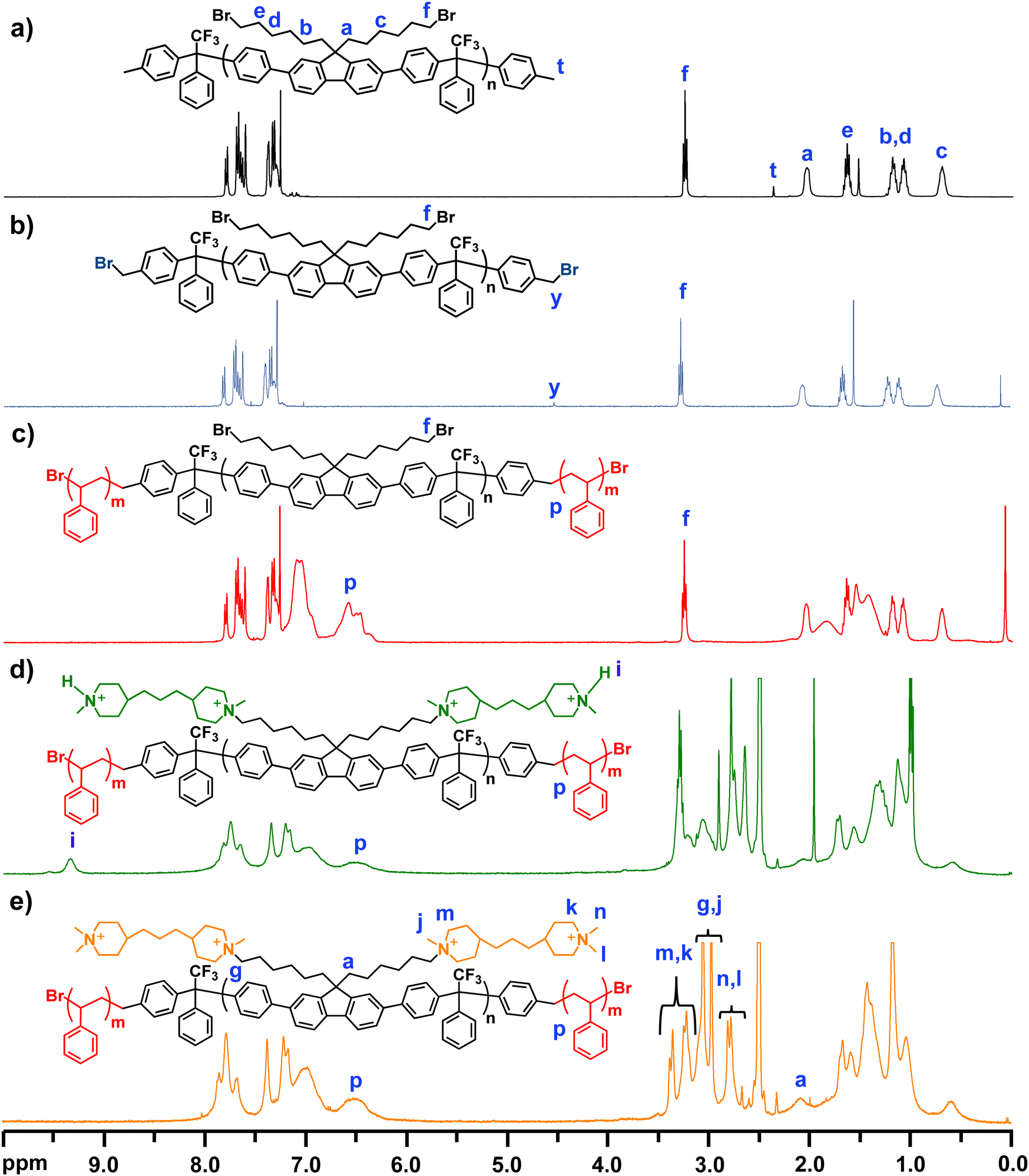 | ||
| Fig. 1 1H NMR spectra of polymer PDPF-Me (a), benzylbrominated macroinitiator PDPF-Br (b), triblock copolymer PDPF-b-PS-38 (c), the semi-quarternized intermediate PDPF-b-PS-bisPip-int (d), and the fully quaternized PDPF-b-PS-bisPip-2.4 (e). | ||
2.3 Membrane preparation
AEMs with a thickness between 50 and 70 μm were cast from 5% solutions of the triblock copolymers in the PDPF-b-PS-bisPip-IEC series dissolved in NMP. Each solution was passed through a syringe filter (Millex LS, 5 μm) onto Petri dishes (∅ = 5 cm) before being transferred into the ventilated explosion-proof casting oven at 80 °C for 48 h. The AEMs were carefully detached from the Petri dishes after immersion in deionized water and were then washed at least 3 times with deionized water before any further characterization.The as-cast AEMs contained both Br− and I− counter ions, and to obtain the pure Br− form the AEMs were immersed in 1 M aq. NaBr at 45 °C for 7 days. The solution was exchanged at least 3 times during this period. Next, the AEMs were thoroughly washed with deionized water and were then stored in fresh deionized water for 48 h at room temperature before further characterization.
2.4 Ion exchange capacity
The theoretical ion exchange capacity (IEC) of the AEMs was calculated based on the 1H NMR data, while the experimental (IECtitr) was determined by Mohr titration. A membrane sample in the Br− form (0.03–0.04 g) was dried under vacuum at 50 °C for 48 h. The dry membrane was weighed and then immersed directly in 0.2 M aq. NaNO3 (25 ml) for 7 days at 45 °C. Then the membrane solution (5 ml) was titrated with ∼0.01 M aq. AgNO3 to determine the concentration of Br− ions, employing 0.1 M aq. K2CrO4 solution as an indicator. The endpoint was determined by a color change from yellow to reddish-brown. Each titration was performed 4 times, and the average value was taken as IECtitr. The IEC of the membrane was converted from its Br− form to the equivalent OH− form (IECOH) as: | (1) |
2.5 Water uptake and swelling
The water uptake of the AEMs in the OH− form was measured gravimetrically and the procedure is outlined below. A membrane in the Br− form was dried under vacuum at 50 °C for 48 h and weighed (WBr−). In order to complete the ion exchange from Br− to OH−, the dry membrane in the Br− form was placed in degassed 1 M aq. NaOH for 48 h under nitrogen atmosphere. The degassed solution was replaced 3 times to ensure complete ion exchange. Assuming successful completion of ion exchange from Br− to OH−, the weight of the membrane in the OH− form was calculated as:| WOH− = WBr− × (1 − 0.0629 × IECBr−). | (2) |
 . The water uptake of the membrane at 20 °C was calculated as:
 | (3) |
The same procedure was applied to 40 °C for 10 h, and 60 and 80 °C for 6 h. Additionally, the hydration number (λ), the number of water molecules per cationic group, was calculated as:
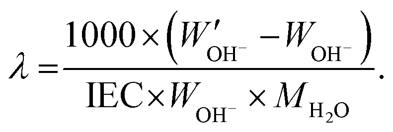 | (4) |
For swelling ratio evaluation, the length (ldry) and thickness (ddry) of membranes in Br− form were measured after the membrane was dried at 50 °C for 48 h, and were assumed to be similar to those in OH− form. After each temperature, the length (lwet) and thickness (dwet) were measured, and in-plane and through-plane swelling ratios were calculated as:
 | (5) |
 | (6) |
The same procedure was followed to obtain the water uptake of the membranes at 20, 40, 60, and 80 °C.
2.6 Atom force microscopy
Atomic force microscopy (AFM) images were obtained using a Bruker Icon Atomic Force Microscope instrument. By tapping mode analysis, the side of the AEM (Br− form) that faced the air during the casting was analyzed by scanning 1 μm × 1 μm areas using a scan rate of 0.498 Hz.2.7 Small-angle X-ray scattering
Small angle X-ray scattering (SAXS) of the AEMs in the Br− form was measured with a SAXLAB ApS system (JJ-Xray, Denmark) combined with a Pilatus detector. The scattering vector (q) was calculated as: | (7) |
 | (8) |
2.8 Thermal properties
The thermal decomposition temperature of the different polymers and AEMs was characterized using a thermogravimetric analyzer (TGA, Q500) from TA Instruments. The precursor copolymers and the AEMs in the Br− form were first kept isothermally at 150 °C for 20 min to eliminate any water residues. The measurements were then performed under nitrogen from 50 to 600 °C at a heating rate of 10 °C min−1, and the thermal decomposition temperature was defined at 5% weight loss (Td,95). A TA instrument Q2000 model differential scanning calorimeter (DSC) was used to analyze the glass transition temperature (Tg) of the precursor copolymers. A heating–cooling–heating cycle between 50 to 240 °C was performed at a heating/cooling rate of 10 °C min−1. The Tg of the precursor copolymers was determined using data from the second heating cycle.2.9 Hydroxide conductivity
A Novocontrol high-resolution dielectric analyzer V 1.01S was used to measure the OH− conductivity of the AEMs. First, the AEMs were ion-exchanged to the OH− form using the same procedure outlined above for the water uptake measurements. The membrane samples were then assembled between two electrodes in a closed cell. An alternating voltage with an amplitude of 50 mV and a frequency range of 107 to 100 Hz was applied while the cell was kept at a fixed temperature. The alternating conductivity (σ) was plotted against the frequency, and the plateau with constant conductivity was taken as the hydroxide conductivity at that temperature. Measurements were carried out under fully hydrated conditions during the temperature sequence 20 °C → 80 °C → 20 °C, and the data from the second cycle were used to obtain the hydroxide conductivity.2.10 Alkaline stability
The stability of AEMs was analyzed by 1H NMR spectroscopy after alkaline treatment. AEM samples were immersed in 2 M aq. NaOH during 672 h at 90 °C. After storage, the AEMs were carefully washed with fresh deionized water. To exchange to the Br− form, AEMs were immersed in 1 M aq. NaBr solution during 48 h and the solution was refreshed at least 3 times during this period. Next, the AEMs were washed several times with deionized water and dried at 50 °C under vacuum, before being dissolved in DMSO-d6 and analyzed by 1H NMR spectroscopy. TFA was added to expose sample signals in the 3–3.5 ppm region, and to protonate any tertiary amine generated by ionic loss (degradation) to make it visible in the spectra.3. Result and discussion
3.1 Polymer synthesis
Four different BAB triblock copolymers were synthesized according to Scheme 1. The copolymers all had an identical fluorene-based middle (A) block, but were flanked by PS outer (B) blocks with different lengths, giving the copolymers different ionic contents and molecular weights. The precursor midblock was synthesized by a Friedel–Crafts-type polyhydroxyalkylation of TFAp, DPBHF, and toluene mediated by TFSA under a nitrogen atmosphere at 0 °C. Using the 2,7-diphenylfluorene monomer DPBHF (instead of a non-phenylated fluorene) facilitated the polycondensation reaction, producing a rigid ether-free backbone polymer. Moreover, this monomer carried two 6-bromohexyl chains, which allowed the tethering of double pairs of piperidinium cations per DPBHF unit in the final block copolymers.The polyhydroxyalkylation reaction takes place in two steps. In the first step, TFSA protonates the carbonyl group of the TFAp monomer to generate an electrophilic cation, which is then attacked by an electron-rich nucleophilic DPBHF monomer to produce an alcohol (carbinol). In the second step, TFSA protonates the carbinol to generate a second cation, which reacts with a second DPBHF monomer to form a 1-phenyl-2,2,2-trifluoroethylidene link between the two DPBHF units.62,63 Due to the difference in the rate between the first and second step, an excess of TFAp (15 mol% excess) was added to enhance the reaction rate of the first step, and hence facilitate the reaction rate and the formation of a high molecular weight polymer.64 In order to introduce benzylic sites to form initiator sites for ATRP at the chain ends of the precursor block, a precise amount of toluene was added 1 h after the polycondensation of TFAp and DPBHF had started, and the reaction was continued for an additional hour. This strategy was employed to ensure the reaction of the mono-functional toluene at the polymer chain ends, while minimizing the reversible trans-alkylation reaction of toluene with the alkylene links in the polymer main chain, that would lead to chain degradation and loss of molecular weight. Due to the second step being faster,62 we expected that all the polymeric chains were terminated by toluene at both chain ends, to produce the PDPF-Me polymer (Scheme 1). This showed a molecular weight of Mn = 20.4 kDa and a dispersity of MwMn−1 = 2.9 (Fig. S1, ESI†).
The molecular structure of PDPF-Me was verified by 1H NMR spectroscopy (Fig. 1(a)). The methylene bromide (–CH2Br, f) protons of the DPBHF units generated a signal at 3.25 ppm, and additional methylene (–CH2–) protons from the alkyl chain generated signals in the region 0.7–2.05 ppm (Fig. 1(a)). The benzylic protons (–CH3, t) of the toluene chain ends of the polymer generated a small signal at 2.3 ppm. Comparing the integrated signal of the methylene bromide signal (f) with that of the benzylic protons at the polymer chain ends (t), enabled the calculation of the number average molecular weight of the polymer. The molecular weight of the precursor polymer calculated from the 1H NMR and SEC data were 25.4 and 20.4 kDa, respectively. The numbers are reasonable close and the discrepancy may be due to the use of PS standards to calibrate the SEC results.
In order to obtain an ATRP macroinitiator for the polymerization of styrene from both chain ends, the benzylic sites of the copolymer PDPF-Me were brominated using NBS and AIBN. An excess of NBS was used to ensure complete benzylbromination of the chain ends. The 1H NMR spectrum of PDPF-Br showed that the signal from the benzylic protons of the toluene chain ends (–CH3) disappeared after the bromination. Instead, a new signal belonging to the benzylbromide (–CH2Br, y) chain ends appeared at 4.51 ppm (Fig. 1(b)). In addition, a small signal (y′) emerged at 7 ppm in the 1H NMR spectrum (Fig. S2, ESI†) from benzyldibromide (–CHBr2) groups formed by double benzylbromination, which may be due to the excess of NBS used in the reaction. By comparing the intensity ratios between signals f, y, and y′, double benzylbromination was found to occur in approximately 20% of the cases. Assuming a random distribution of the double benzylbrominated sites at the polymer chain ends, gave that approximately 64% of the polymers chains had single brominated sites at both ends, 32% had a double brominated site at one of the ends, and 4% had double brominated sites at both ends.
ATRP was used to polymerize styrene from the benzylbromide and benzyldibromide chain ends of the fluorene-based macroinitiator PDFP-Br, employing the CuBr/bpy system at 120 °C in toluene. The molar ratio of PDPF-Br![[thin space (1/6-em)]](https://www.rsc.org/images/entities/char_2009.gif) :CuBr:bipy was kept at 1:4:8, because at lower ratios (e.g., 1:2:4) the ATRP results were irreproducible. This was possibly due to the high molecular weight and rigid backbone structure of the macroinitiator. Fig. 1(c) shows that the 1H NMR signals from the benzylbromide and benzyldibromide sites disappeared. In addition, two broad signals belonging to the aromatic protons in the PS blocks appeared in the region 6.5–7.5 ppm. Four BAB triblock copolymers with different PS block lengths were synthesized from the same macroinitiator and were labeled as PDPF-b-PS-x, where x gives the PS block content in wt%. The PS block content was controlled by monitoring the progress of the ATRP by 1H NMR spectroscopy during the reaction, and was adjusted to reach the desired final IEC values of the AEMs in the OH− form (i.e., 2.0, 2.2, 2.4 and 2.6 mequiv. g−1). The PS content was determined by comparing the integrals of the methylene bromide signal (f) from the bromoalkyl chains and the signal from the two protons in ortho-position in the PS rings (p), which appeared at 3.5 and 6.3–6.7 ppm, respectively. The number average molecular weight and dispersity of the precursor triblock copolymers were analyzed by SEC, and the results indicated, as expected, that Mn increased with increasing PS content (Table 1). The SEC chromatograms of all the precursors showed a shoulder towards the high molecular weight side (Fig. S3, ESI†). This was most probably due to the difference in the ATRP functionality (1 or 2) of the brominated chain ends, which in turn generated macroinitiator with different functionalities (i.e., 64% di-, 32% tri- and 4% tetrafunctional), leading to different PS contents and architectures of the copolymer molecules in the samples. Moreover, 1H NMR spectroscopy (Fig. S4, ESI†) was also used to analyze the number average molecular weight of the precursor block copolymers by assuming that double brominated chain ends generated PS chains of similar length due to the similarity in chemical structure and reactivity of the single and double brominated initiator sites65 (Fig. S5, ESI†), and in addition the radical concentration is low enough to prevent recombination or disproportion termination reactions.65 The average number molecular weight of precursor triblock copolymers generated by a macroinitiator with two single brominated initiator sites was calculated and is shown in the Table 1, and the corresponding molecular weights from tri- and tetrafunctional macroinitiators are shown in Table S1 (ESI†). The Mn of the precursor block copolymers increased with increasing the PS content.
:CuBr:bipy was kept at 1:4:8, because at lower ratios (e.g., 1:2:4) the ATRP results were irreproducible. This was possibly due to the high molecular weight and rigid backbone structure of the macroinitiator. Fig. 1(c) shows that the 1H NMR signals from the benzylbromide and benzyldibromide sites disappeared. In addition, two broad signals belonging to the aromatic protons in the PS blocks appeared in the region 6.5–7.5 ppm. Four BAB triblock copolymers with different PS block lengths were synthesized from the same macroinitiator and were labeled as PDPF-b-PS-x, where x gives the PS block content in wt%. The PS block content was controlled by monitoring the progress of the ATRP by 1H NMR spectroscopy during the reaction, and was adjusted to reach the desired final IEC values of the AEMs in the OH− form (i.e., 2.0, 2.2, 2.4 and 2.6 mequiv. g−1). The PS content was determined by comparing the integrals of the methylene bromide signal (f) from the bromoalkyl chains and the signal from the two protons in ortho-position in the PS rings (p), which appeared at 3.5 and 6.3–6.7 ppm, respectively. The number average molecular weight and dispersity of the precursor triblock copolymers were analyzed by SEC, and the results indicated, as expected, that Mn increased with increasing PS content (Table 1). The SEC chromatograms of all the precursors showed a shoulder towards the high molecular weight side (Fig. S3, ESI†). This was most probably due to the difference in the ATRP functionality (1 or 2) of the brominated chain ends, which in turn generated macroinitiator with different functionalities (i.e., 64% di-, 32% tri- and 4% tetrafunctional), leading to different PS contents and architectures of the copolymer molecules in the samples. Moreover, 1H NMR spectroscopy (Fig. S4, ESI†) was also used to analyze the number average molecular weight of the precursor block copolymers by assuming that double brominated chain ends generated PS chains of similar length due to the similarity in chemical structure and reactivity of the single and double brominated initiator sites65 (Fig. S5, ESI†), and in addition the radical concentration is low enough to prevent recombination or disproportion termination reactions.65 The average number molecular weight of precursor triblock copolymers generated by a macroinitiator with two single brominated initiator sites was calculated and is shown in the Table 1, and the corresponding molecular weights from tri- and tetrafunctional macroinitiators are shown in Table S1 (ESI†). The Mn of the precursor block copolymers increased with increasing the PS content.
| Precursor | PS content (wt%) | Degree of polymerisationa of the PS blocks | M n of PS block (kg mol−1) | M n (kg mol−1) | M n (kg mol−1) | Đ M | T g (°C) | T d,95 (°C) |
|---|---|---|---|---|---|---|---|---|
| a Analyzed by 1H NMR spectroscopy. b Measured by SEC. c Analyzed by DSC. d Measured by TGA. | ||||||||
| PDPF-Me | 0 | 0 | 0 | 25.4 | 20.4 | 2.9 | 196 | 324 |
| PDPF-b-PS-30 | 30 | 30.5 | 4.9 | 30.3 | 22.4 | 5.7 | 106 | 312 |
| PDPF-b-PS-38 | 38 | 38.7 | 6.2 | 31.6 | 24.0 | 4.9 | 106 | 314 |
| PDPF-b-PS-43 | 43 | 43.8 | 7.1 | 32.5 | 24.9 | 4.6 | 106 | 312 |
| PDPF-b-PS-48 | 48 | 48.8 | 7.9 | 33.3 | 25.0 | 4.6 | 106 | 309 |
The thermal decomposition temperature (Td,95, defined at 95% weight loss) and the glass transition temperature (Tg) of PDPF-Me, PDPF-b-PS-30, -38, -43, and -48 were measured by TGA and DSC, respectively. The TGA results showed that the Td,95 of the precursor triblock polymers was around ∼10 °C lower than for PDPF-Me (Table 1). The TGA traces indicated at least two distinct thermal decomposition steps (Fig. S6, ESI†). First, the PS blocks and the flexible alkyl chains most probably decomposed first between 300–450 °C, followed by the loss of the fluorene-based backbone at around 500 °C. The DSC trace from PDPF-Me showed a Tg at 196 °C of the stiff fluorene backbone polymer, while the precursor triblock copolymers only showed a Tg value at 106 °C from the PS blocks, instead of the two expected from the two blocks (phases) present (Fig. S7, ESI†).
In the final synthetic step, the midblocks of the triblock copolymers PDPF-b-PS-30, -38, -43, and -48 were densely tethered with piperidinium cations via two consecutive Menshutkin reactions. In the first reaction, the bromoalkyl side chains of the fluorene units were first reacted with an excess of 4,4′-trimethylenebis(1-methylpiperidine) (bisPip) in DMAc at 85 °C. This was followed by the second Menshutkin reaction, where methyl iodide was used to quaternize the terminal piperidine rings of the tethered bisPip units to give PDPF-b-PS-bisPip-2.0, -2.2, -2.4, and -2.6, respectively. Fig. 1(d) presents the 1H NMR spectrum of the PDPF-b-PS-bisPip-2.4 intermediate, where the terminal piperidine rings in the side chains had not yet been quaternized. As seen in the spectrum after adding 10% TFA to the solution, a new 1H NMR signal from the (terminal) protonated tertiary piperidine (N+–H) arose at 9.37 ppm. The signals from the methylene protons in the bisPip unit appeared in the 1.1–1.8 ppm and overlapped with the methylene protons from the PS blocks and the alkyl chains. Moreover, the signals from the N-methyl (N–CH3, j, l) and N-methylene (N–CH2–, m, g, k) units appeared in the region 2.9 to 3.4 ppm, and overlapped with the solvent peak (Fig. S8, ESI†). After the second quaternization reaction with methyl iodide, the sample was dissolved in DMSO-d6/TFA (9:1, v:v), and the signal from the protonated tertiary piperidine disappeared, as expected. In addition, the signals from the N-methyl (j, n, l) and N-methylene (m, g, k) units were shifted to between 2.8 and 3.4 ppm (Fig. 1(e)).
3.2 Membrane preparation and morphology
Flexible AEMs of all the BAB triblock copolymers in the PDPF-b-PS-bisPip-IEC series were cast from NMP solutions at 80 °C. SAXS was subsequently employed to study the morphology of the AEMs in the bromide form. AEMs based on corresponding statistical copolymers did not show any ionomer peaks (Fig. S9, ESI†), most probably due to the high stiffness of the polymer backbone, which prevents the formation of regular ionic clusters.45 In contrast, all the current BAB triblock copolymer AEMs showed clear ionomer peaks. As seen from the scattering profiles in Fig. 2, scattering peaks appeared at q = 0.41, 0.45, 0.43, and 0.42 nm−1 for PDPF-b-PS-bisPip-2.6, -2.4, -2.2, and -2.0, respectively, which corresponded to characteristic distances of d = 15.4, 13.8, 14.5 and 14.9 nm, respectively (Fig. 2). The magnitude of d hinted that this scattering most probably originated from the microphase separation between the A and B blocks. Since all the AEMs were synthesized from the same macroinitiator, the difference between the samples was in the length and content of the PS blocks. Hence, d was expected to increase with the PS block length, as seen with the values of PS-bisPip-2.4, -2.2, and -2.0. The discrepancy in the case of PS-bisPip-2.6 may hint that this sample, with the shortest PS blocks in the series, had a different morphology. In addition, the AEMs showed weak scattering peaks at q = 0.80, 1.03, 1.06, and 1.09 nm−1 for PDPF-b-PS-bisPip-2.6, -2.4, -2.2, -2.0, respectively, corresponding to d = 7.6, 6.1, 6.0, and 5.8 nm, respectively (Fig. 2). In this case, the smaller magnitude of d suggested that the scattering originated from ionic clustering in the highly ion-concentrated phase domain of the triblock copolymers. The value of d increased with decreasing content of the PS blocks, and thus increasing IEC, of the triblock copolymer AEMs.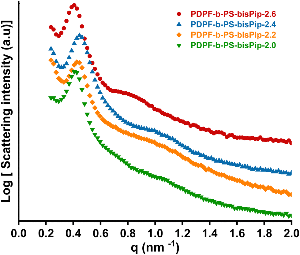 | ||
| Fig. 2 SAXS profiles of the BAB triblock copolymer AEMs in the PDPF-b-bisPip-IEC series in the dry bromide form. | ||
The surface morphology of the triblock copolymer AEMs was studied by AFM. Phase images of the surfaces facing the air during the casting were obtained in the tapping mode. As seen from the representative phase images shown in Fig. 3, the AEMs clearly showed microphase separation between the A and B blocks of the triblock copolymers, where the dark and bright areas indicated the soft ionic phase domain and hard hydrophobic phase domain, respectively. As expected, the size of the hydrophobic phase domain (bright areas) gradually increased with the PS block content in the triblock polymer, i.e., PDPF-b-PS-bisPip-2.0 with the highest PS block content (35%) showed a larger hydrophobic phase domain compared to PDPF-b-PS-bisPip-2.6, which possess the lowest PS content (20%). In summary, both SAXS and AFM data revealed that the triblock copolymer AEMs had a microphase separated morphology that can be expected to greatly influence the water uptake, ionic conductivity, and alkaline stability.
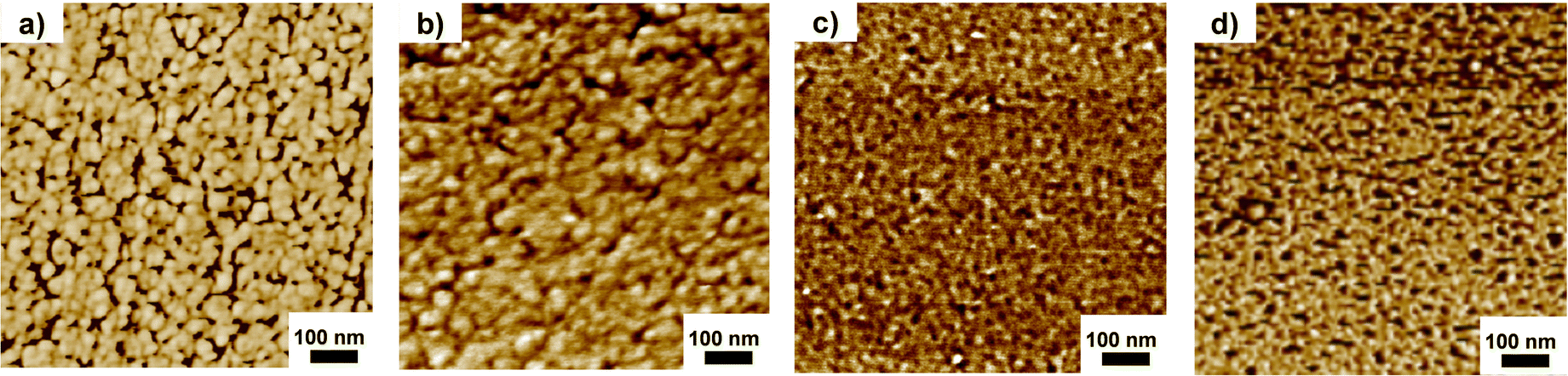 | ||
| Fig. 3 AFM phase images of PDPF-b-bisPip-2.0 (a), PDPF-b-bisPip-2.2 (b), PDPF-b-bisPip-2.4 (c) and PDPF-b-bisPip-2.6 (d). | ||
3.3 Water uptake and swelling
The water content of the AEM is crucial for ionic dissociation and the formation of a percolating water-rich phase domain to enable efficient anion transportation across the membrane. However, an excessive water uptake may not only compromise the mechanical properties of the membrane, but can also negatively affect the hydroxide conductivity due to a dilution effect of the charge carrying anions. The water uptake of the current AEMs in the hydroxide form was measured between 20 and 80 °C, and the results are shown in Fig. 4(a). As expected, the water uptake depended strongly on both temperature and IEC. PDPF-b-PS-bisPip-2.6, with the highest IEC value (2.6 mequiv. g−1) showed the highest water uptake, 335 and 528% at 20 and 80 °C, respectively. At 20 °C, PDPF-b-PS-bisPip-2.0 showed a water uptake of 73%, and as the temperature was increased to 80 °C, the water uptake increased to 123%. We have previously synthesized and investigated AEMs based on statistical copolymers functionalized with double pairs of piperidinium cations.45 Compared with these AEMs, the present ones based on triblock copolymers (e.g., PDPF-b-PS-bisPip-2.0) took up less water at a given IEC (Table 2).45 The lower water uptake of present AEMs may be attributed to the presence of a large glassy (Tg ∼ 100 °C) PS phase domain, which mechanically interlocked the hydrophilic (ionic) phase domain to reduce the water uptake and swelling. Moreover, the water swelling of the current AEMs was not isotropic. At 80 °C, the swelling was higher in the through-plane direction than in the in-plane, which may indicate that the phase domains formed by the blocks had a different orientation in these directions. PDPF-b-PS-bisPip-2.6 showed the highest swelling ratios, i.e., 30% through-plane and 18% in-plane at 80 °C, and PDPF-b-PS-bisPip-2.0 exhibited the lowest ratios (19 and 12% through- and in-plane, respectively). At a given IEC, PDPF-b-PS-bisPip-2.0 showed lower through- and in-plane swelling ratios (19 and 12%, respectively) at 80 °C compared to the corresponding AEMs based on statistical copolymers (39 and 18%, respectively) (Table 2). The difference in the swelling between statistical copolymer and block copolymer can be explained by the fact that the hydrophobic domain size of the latter AEMs were much larger and thus better restricted the water uptake and swelling.52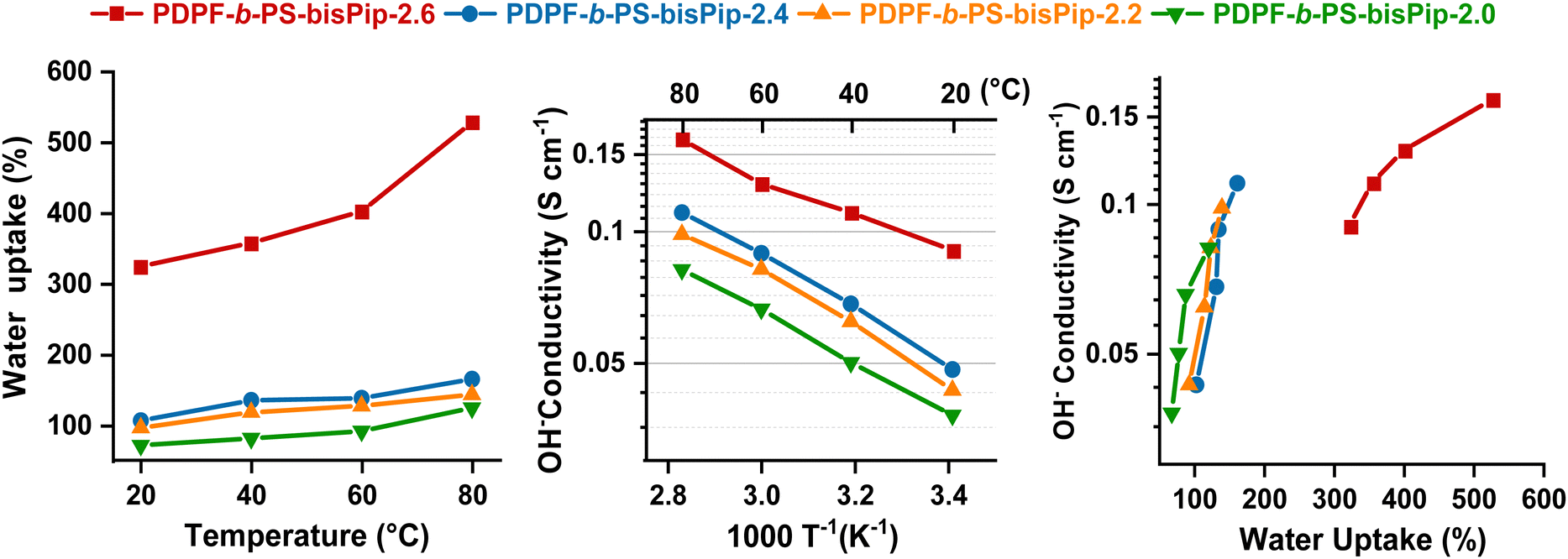 | ||
| Fig. 4 Data of the AEMs in the fully hydrated hydroxide form: water uptake as a function of temperature (a), hydroxide conductivity as a function of T−1 (b), and hydroxide conductivity as a function of water uptake. | ||
| AEM | Precursor polymer | IECNMRa [mequiv. g−1] | IECtitrb [mequiv. g−1] | WU80c [wt%] | SWOH−c (%) | λ | σ OH− [mS cm−1] | T d,95,d [°C] | |
|---|---|---|---|---|---|---|---|---|---|
| In-plane | Through-plane | ||||||||
| a Calculated from the 1H NMR spectra of precursor polymers in the OH− form (Br− form within parenthesis). b Calculated from titration data of AEMs in the OH− form (Br− form within parenthesis). c Measured in the OH− form at 80 °C immersed in liquid water (fully hydrated). d Analyzed by TGA. | |||||||||
| Triblock copolymers (data from current study) | |||||||||
| PDPF-b-PS-bisPip-2.6 | PDPF-b-PS-30 | 2.57 (2.21) | 2.45 (2.12) | 528 | 18 | 30 | 120 | 161 | 263 |
| PDPF-b-PS-bisPip-2.4 | PDPF-b-PS-38 | 2.35 (2.04) | 2.23 (1.96) | 164 | 17 | 23 | 41 | 110 | 262 |
| PDPF-b-PS-bisPip-2.2 | PDPF-b-PS-43 | 2.18 (1.91) | 2.13 (1.88) | 142 | 15 | 21 | 37 | 98 | 254 |
| PDPF-b-PS-bisPip-2.0 | PDPF-b-PS-48 | 2.03 (1.80) | 1.94 (1.73) | 123 | 12 | 19 | 35 | 81 | 248 |
| Statistical copolymers (data from previous study45) | |||||||||
| PDPF-bisPip-2.8 | PDPF-Br-81 | 2.81 (2.39) | 2.65 (2.27) | 557 | 34 | 58 | 120 | 150 | 247 |
| PDPF-bisPip-2.4 | PDPF-Br-71 | 2.41 (2.09) | 2.32 (2.03) | 257 | 22 | 43 | 70 | 106 | 246 |
| PDPF-bisPip-2.0 | PDPF-Br-53 | 2.03 (1.80) | 2.02 (1.81) | 196 | 18 | 39 | 53 | 85 | 247 |
| PDPF-Pip-2.0 | PDPF-Br-40 | 2.02 (1.79) | 2.03 (1.80) | 139 | 14 | 35 | 36 | 76 | 241 |
3.4 Hydroxide conductivity
The hydroxide conductivity of AEMs depends on several parameters, including the IEC, water uptake, degree of ionic dissociation, temperature, as well as the morphology. In the present case, the hydroxide conductivity of the AEMs was measured by EIS between 20 and 80 °C in fully hydrated conditions using a two-probe cell. As shown in Fig. 4(b), the ionic conductivity of the AEMs was directly influenced by the IEC, water uptake, and temperature. At 80 °C, PDPF-b-PS-bisPip-2.6 with the highest IEC reached almost twice the conductivity (161 mS cm−1) of PDPF-b-PS-bisPip-2.0 with the lowest IEC value (81 mS cm−1). Moreover, compared at the same IEC value, the present AEMs based on the BAB triblock copolymers reached higher hydroxide conductivity than the corresponding AEMs based on statistical copolymers.45 This may be attributed to the more pronounced phase separation, and hence the higher local ionic concentration of the former membranes, which facilitated the formation of an efficient percolating water-rich ion-conducting phase domain.3.5 Thermal stability
TGA measurements were carried out to obtain the thermal decomposition temperature (Td,95) of the AEMs in the bromide form under a nitrogen atmosphere. Before any measurement, the samples were subjected to an isotherm at 150 °C for 20 min to remove any residual water. As expected, the thermal stability decreased significantly after introducing the piperidinium cations, as compared to the precursor triblock polymers. As seen from the TGA traces in Fig. 5, all the current BAB triblock copolymer AEMs thermally decomposed in at least three quite distinguishable steps. The first step began just above 200 °C and may be attributed to the decomposition of the cationic groups, while the second one occurred between 350–400 °C and may be connected to the degradation of the alkyl chains of the middle (A) block and PS (B) blocks. The third step started above 450 °C, and was most probably connected with the decomposition of the backbone of the (A) midblock. The thermal decomposition temperature of four AEMs varied in the quite narrow range Td,95 = 248–263 °C, and seemingly decreased with the PS content. However, since the midblock was the same in all the triblock copolymers, this might be a purely kinetic effect, i.e., the diffusion rate of the degradation products from the first step may decrease with increasing content of the glassy PS blocks.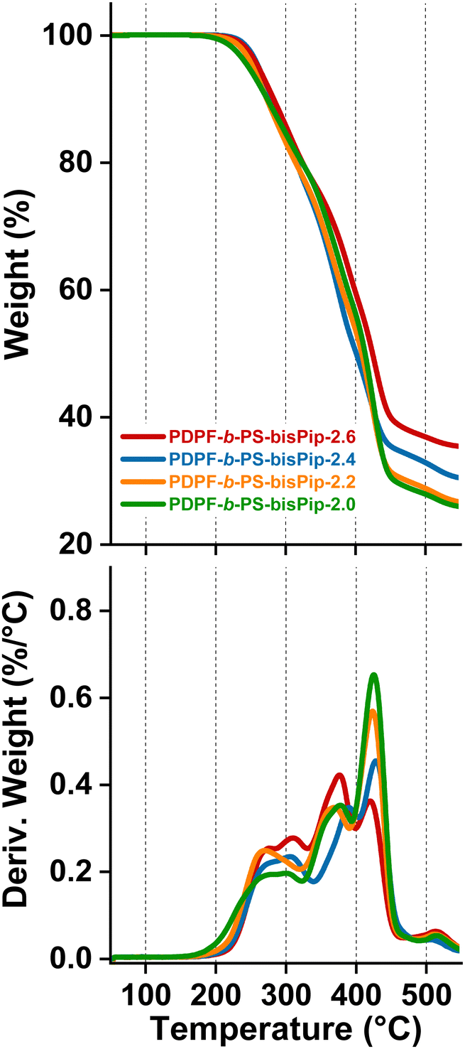 | ||
| Fig. 5 TGA traces of the triblock AEMs in the PDPF-b-PS-bisPip-IEC series (top) and the corresponding first derivatives (bottom). | ||
3.6 Alkaline stability
Achieving sufficient long-term alkaline stability is the most critical challenge in the development of AEMs for fuel cell and water electrolysis applications. The alkaline stability of the current AEMs was studied by observing changes in the 1H NMR spectra before and after alkaline stability treatment. Careful 1H NMR analysis allows the quantitative calculation of the level of ionic loss and AEM degradation, and also to elucidate degradation pathways. The alkaline treatment was performed by storing sample pieces of the AEMs in 2 and 5 M aq. NaOH solutions for 672 and 168 h, respectively, at 90 °C. After storage, the samples were immersed in 1 M aq. NaBr to obtain the bromide form, followed by repeated washing with deionized water to remove residual NaBr. This would also remove any low molecular weight degradation products formed during the alkaline treatment. Before dissolving the washed samples for the NMR analysis, the flexible and transparent membranes were dried under vacuum at room temperature for 48 h. To the DMSO-d6 solution was added approx. 10 vol% of TFA in order to shift the water signal to above 10 ppm, and to protonate any tertiary amines formed through ionic loss, e.g., through elimination and substitution reactions. Fig. 6 shows the 1H NMR spectra of AEMs before and after being immersed in 2 M aq. NaOH at 90 °C for 672 h. No new signals or significant changes were detected in corresponding 1H NMR spectra after the alkaline treatment. Moreover, the membrane samples remained flexible and transparent after the 672 h storage period. This finding demonstrated the outstanding alkaline stability of the piperidinium-tethered triblock copolymer AEMs.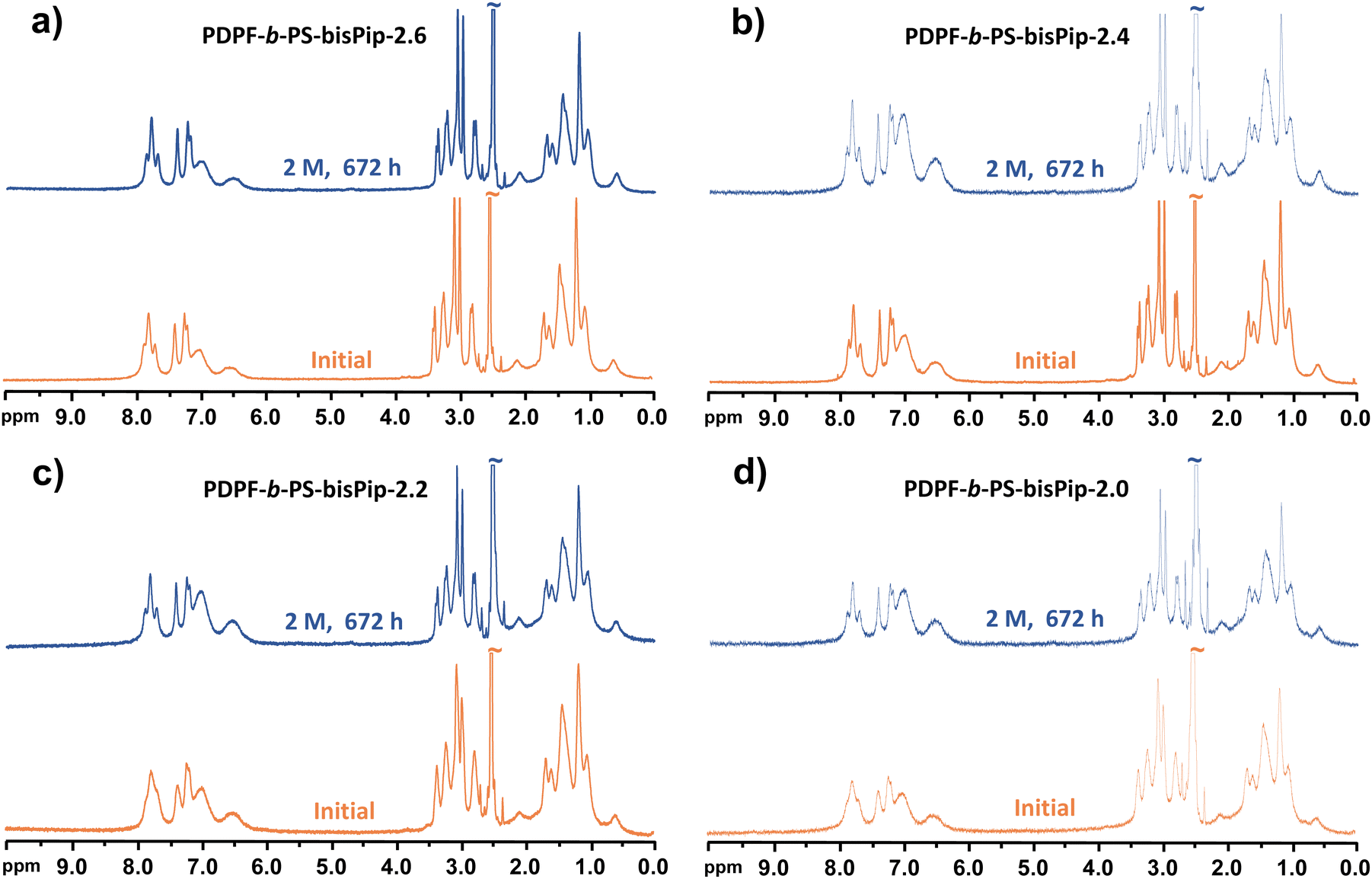 | ||
| Fig. 6 1H NMR spectra before and after alkaline treatment of PDPF-b-PS-bisPip-2.6 (a), PDPF-b-PS-bisPip-2.4 (b), PDPF-b-PS-bisPip-2.2 (c), and PDPF-b-PS-bisPip-2.0 (d) in 2 M aq. NaOH for 672 h at 90 °C. | ||
After treatment under the more severe alkaline conditions, i.e., 5 M aq. NaOH at 90 °C during 168 h, the AEMs were still flexible and transparent. However, they were no longer soluble in the DMSO-d6, which prevented NMR analysis. This can likely be attributed to the formation of some amino alcoholates during an ionic loss via substitution reactions, which might then have attacked piperidinium rings to form ether-containing crosslinks.
4. Conclusions
A series of ether-free BAB triblock copolymers containing central blocks of poly(fluorene alkylene), densely tethered with piperidinium cations via flexible alkyl chains, and flanking hydrophobic PS blocks were successfully synthesized and studied as AEMs. The block copolymers were prepared by a sequence of polyhydroxyalkylation, benzylbromination and ATRP. The benzylbromination was selectively directed to the toluene chain ends, but resulted in both monobromobenzyl and dibromobenzyl sites, which resulted in the formation of predominantly mono- but also some difunctional ATRP initiator sites. This, in turn, added to the dispersity of the block copolymers. The desired IECs of the final AEMs in the series were reached by conveniently controlling the ATRPs to obtain specific PS contents, and to ensure that the Menshutkin reactions were quantitative. Both the SAXS and the AFM results confirmed the microphase separation of the triblock copolymers to form morphologies with well-connected hydrophilic (ionic) nanophase domains. This, combined with the very high ionic content (IEC) of the center block, and the BAB block configuration with hydrophobic and glassy PS (B) blocks that restricted the water uptake, resulted in high hydroxide conductivities. In addition, the block copolymer AEMs possessed an excellent thermal and alkaline stability. When compared with corresponding AEMs based on statistical copolymers, the present BAB triblock copolymer AEMs showed a more restricted water uptake, a higher alkaline stability, and a higher hydroxide conductivity at a given IEC. Consequently, his work provides valuable insights into how to molecular design and prepare block copolymers to improve the performance and durability of AEMs for AEMFC and AEMEC applications.Author contributions
Andrit Allushi: methodology, data acquisition, investigation, validation, writing original draft, writing – review & editing. Pegah Mansouri Bakvand: data acquisition, investigation, methodology, validation, Haiyue Gong: data acquisition, investigation, methodology, validation. Patric Jannasch: conceptualization, funding acquisition, supervision, writing – review & editing.Conflicts of interest
There are no conflicts of interest to declare.Acknowledgements
We thank the Swedish Energy Agency (grants 50519-1, 45057-1, 37806-3 and 45515-3), the Swedish Research Council (grant 2019-03639), the Swedish Foundation for Strategic Research, SSF (grants EM16-0060 and ARC19-0026), and the Royal Physiographic Society of Lund for financial support. We are also thankful to Peter Holmqvist for his help with the X-ray measurements.References
- J. R. Varcoe, P. Atanassov, D. R. Dekel, A. M. Herring, M. A. Hickner, P. A. Kohl, A. R. Kucernak, W. E. Mustain, K. Nijmeijer, K. Scott, T. W. Xu and L. Zhuang, Energy Environ. Sci., 2014, 7, 3135–3191 RSC.
- M. Hannan, M. M. Hoque, A. Mohamed and A. Ayob, Renewable Sustainable Energy Rev., 2017, 69, 771–789 CrossRef.
- M. A. Hickner, Electrochem. Soc. Interface, 2017, 26, 69–73 CrossRef CAS.
- C. G. Arges and L. Zhang, ACS Appl. Energy Mater., 2018, 1, 2991–3012 CrossRef CAS.
- D. R. Dekel, J. Power Sources, 2018, 375, 158–169 CrossRef CAS.
- D. Li, A. R. Motz, C. Bae, C. Fujimoto, G. Yang, F.-Y. Zhang, K. E. Ayers and Y. S. Kim, Energy Environ. Sci., 2021, 14, 3393–3419 RSC.
- Z. Tao, C. Wang, X. Zhao, J. Li and M. D. Guiver, Adv. Mater. Technol., 2021, 6, 2001220 CrossRef CAS.
- H. Chen, R. Tao, K.-T. Bang, M. Shao and Y. Kim, Adv. Energy Mater., 2022, 12, 2200934 CrossRef CAS.
- N. Chen and Y. M. Lee, Trends Chem., 2022, 4, 236–249 CrossRef CAS.
- Z. Yuan, L. Liang, Q. Dai, T. Li, Q. Song, H. Zhang, G. Hou and X. Li, Joule, 2022, 6, 884–905 CrossRef CAS.
- H. Zarrin, J. Wu, M. Fowler and Z. Chen, J. Membr. Sci., 2012, 394–395, 193–201 CrossRef CAS.
- F. Zhang, T. Li, W. Chen, X. Wu, X. Yan, W. Xiao, Y. Zhang, X. Wang and G. He, ACS Appl. Mater. Interfaces, 2021, 13, 10490–10499 CrossRef CAS PubMed.
- J. J. Han, H. Q. Peng, J. Pan, L. Wei, G. W. Li, C. Chen, L. Xiao, J. T. Lu and L. Zhuang, ACS Appl. Mater. Interfaces, 2013, 5, 13405–13411 CrossRef CAS PubMed.
- C. G. Arges and V. Ramani, Proc. Natl. Acad. Sci. U. S. A., 2013, 110, 2490–2495 CrossRef CAS PubMed.
- J. J. Han, Q. Liu, X. Q. Li, J. Pan, L. Wei, Y. Wu, H. Q. Peng, Y. Wang, G. W. Li, C. Chen, L. Xiao, J. T. Lu and L. Zhuang, ACS Appl. Mater. Interfaces, 2015, 7, 2809–2816 CrossRef CAS PubMed.
- T. H. Pham and P. Jannasch, ACS Macro Lett., 2015, 4, 1370–1375 CrossRef CAS PubMed.
- H. S. Dang and P. Jannasch, J. Mater. Chem. A, 2017, 5, 21965–21978 RSC.
- Y. Zhu, Y. He, X. Ge, X. Liang, M. A. Shehzad, M. Hu, Y. Liu, L. Wu and T. Xu, J. Mater. Chem. A, 2018, 6, 527–534 RSC.
- N. Chen and Y. M. Lee, Prog. Polym. Sci., 2021, 113, 101345 CrossRef CAS.
- K. F. L. Hagesteijn, S. X. Jiang and B. P. Ladewig, J. Mater. Sci., 2018, 53, 11131–11150 CrossRef CAS.
- W. You, K. J. T. Noonan and G. W. Coates, Prog. Polym. Sci., 2020, 100, 101177 CrossRef CAS.
- W. E. Mustain, M. Chatenet, M. Page and Y. S. Kim, Energy Environ. Sci., 2020, 13, 2805–2838 RSC.
- W. You, E. Padgett, S. N. MacMillan, D. A. Muller and G. W. Coates, Proc. Natl. Acad. Sci. U. S. A., 2019, 116, 9729–9734 CrossRef CAS PubMed.
- J. Muller, A. Zhegur, U. Krewer, J. R. Varcoe and D. R. Dekel, ACS Mater. Lett., 2020, 2, 168–173 CrossRef CAS PubMed.
- U. Salma and Y. Nagao, Polym. Degrad. Stab., 2020, 179, 109299 CrossRef CAS.
- Z. Y. Wang, M. Mandal, S. Sankarasubramanian, G. Huang, P. A. Kohl and V. K. Ramani, ACS Appl. Energy Mater., 2020, 3, 4449–4456 CrossRef CAS.
- K. Yang, X. M. Chu, X. J. Zhang, X. F. Li, J. F. Zheng, S. H. Li, N. W. Li, T. A. Sherazi and S. B. Zhang, J. Membr. Sci., 2020, 603, 118025 CrossRef CAS.
- N. Chen, C. Hu, H. H. Wang, S. P. Kim, H. M. Kim, W. H. Lee, J. Y. Bae, J. H. Park and Y. M. Lee, Angew. Chem., Int. Ed., 2021, 60, 7710–7718 CrossRef CAS PubMed.
- A. M. Ahmed Mahmoud and K. Miyatake, J. Membr. Sci., 2022, 643, 120072 CrossRef CAS.
- C. Hu, J. H. Park, H. M. Kim, H. H. Wang, J. Y. Bae, N. Y. Kang, N. Chen and Y. M. Lee, J. Membr. Sci., 2022, 647 Search PubMed.
- H. Tang, K. Geng, L. Wu, J. Liu, Z. Chen, W. You, F. Yan, M. D. Guiver and N. Li, Nat. Energy, 2022, 7, 153–162 CrossRef CAS.
- E. J. Park and Y. S. Kim, J. Mater. Chem. A, 2018, 6, 15456–15477 RSC.
- A. D. Mohanty and C. Bae, J. Mater. Chem. A, 2014, 2, 17314–17320 RSC.
- A. D. Mohanty, C. Y. Ryu, Y. S. Kim and C. Bae, Macromolecules, 2015, 48, 7085–7095 CrossRef CAS.
- W. You, K. M. Hugar, R. C. Selhorst, M. Treichel, C. R. Peltier, K. J. T. Noonan and G. W. Coates, J. Org. Chem., 2021, 86, 254–263 CrossRef CAS PubMed.
- J. Xue, J. Zhang, X. Liu, T. Huang, H. Jiang, Y. Yin, Y. Qin and M. D. Guiver, Electrochem. Energy Rev., 2022, 5, 348–400 CrossRef CAS.
- M. G. Marino and K. D. Kreuer, ChemSusChem, 2015, 8, 513–523 CrossRef CAS PubMed.
- N. Chen, Y. Jin, H. Liu, C. Hu, B. Wu, S. Xu, H. Li, J. Fan and Y. M. Lee, Angew. Chem., Int. Ed., 2021, 60, 19272–19280 CrossRef CAS PubMed.
- T. H. Pham, A. Allushi, J. S. Olsson and P. Jannasch, Polym. Chem., 2020, 11, 6953–6963 RSC.
- X. Wang, W. B. Sheng, Y. H. Shen, L. Liu, S. Dai and N. W. Li, J. Membr. Sci., 2019, 587, 117135 CrossRef CAS.
- F. Wang, B. X. Xue, S. Y. Zhou, J. F. Zheng, S. H. Li, S. B. Zhang and T. A. Sherazi, J. Membr. Sci., 2019, 591, 117334 CrossRef.
- S. Noh, J. Y. Jeon, S. Adhikari, Y. S. Kim and C. Bae, Acc. Chem. Res., 2019, 52, 2745–2755 CrossRef CAS PubMed.
- T. H. Pham, J. S. Olsson and P. Jannasch, J. Mater. Chem. A, 2018, 6, 16537–16547 RSC.
- J. S. Olsson, T. H. Pham and P. Jannasch, Adv. Funct. Mater., 2018, 28, 1702758 CrossRef.
- A. Allushi, T. H. Pham and P. Jannasch, J. Membr. Sci., 2021, 632, 119376 CrossRef CAS.
- L. Wang and M. A. Hickner, Soft Matter, 2016, 12, 5359–5371 RSC.
- S. Gong, L. Bai, L. Li, N. A. Qaisrani, L. Ma, G. He and F. Zhang, Int. J. Hydrogen Energy, 2021, 46, 2269–2281 CrossRef CAS.
- M. Tanaka, K. Fukasawa, E. Nishino, S. Yamaguchi, K. Yamada, H. Tanaka, B. Bae, K. Miyatake and M. Watanabe, J. Am. Chem. Soc., 2011, 133, 10646–10654 CrossRef CAS PubMed.
- J. S. Olsson, T. H. Pham and P. Jannasch, J. Membr. Sci., 2019, 578, 183–195 CrossRef CAS.
- F. Wang, C. Li, J. Sang, Y. Cui and H. Zhu, Int. J. Hydrogen Energy, 2021, 46, 36301–36313 CrossRef CAS.
- A. N. Lai, L. S. Wang, C. X. Lin, Y. Z. Zhuo, Q. G. Zhang, A. M. Zhu and Q. L. Liu, ACS Appl. Mater. Interfaces, 2015, 7, 8284–8292 CrossRef CAS PubMed.
- C. X. Lin, H. Y. Wu, L. Li, X. Q. Wang, Q. G. Zhang, A. M. Zhu and Q. L. Liu, ACS Appl. Mater. Interfaces, 2018, 10, 18327–18337 CrossRef CAS PubMed.
- X. Dong, B. Xue, H. Qian, J. Zheng, S. Li and S. Zhang, J. Power Sources, 2017, 342, 605–615 CrossRef CAS.
- X. Zhang, Q. Shi, P. Chen, J. Zhou, S. Li, H. Xu, X. Chen and Z. An, Polym. Chem., 2018, 9, 699–711 RSC.
- M. Zhu, X. Zhang, Y. Wang, Y. Wu, H. Wang, M. Zhang, Q. Chen, Z. Shen and N. Li, J. Membr. Sci., 2018, 554, 264–273 CrossRef CAS.
- J. Y. Jeon, S. Park, J. Han, S. Maurya, A. D. Mohanty, D. Tian, N. Saikia, M. A. Hickner, C. Y. Ryu, M. E. Tuckerman, S. J. Paddison, Y. S. Kim and C. Bae, Macromolecules, 2019, 52, 2139–2147 CrossRef CAS.
- Q.-G. Chen and M.-T. Lee, Polymers, 2022, 14, 2860 CrossRef CAS PubMed.
- J. Sang, L. Yang, Z. Li, F. Wang, Z. Wang and H. Zhu, Electrochim. Acta, 2022, 403, 139500 CrossRef CAS.
- J. Sang, L. Yang, F. Wang, Z. Wang and H. Zhu, ACS Appl. Energy Mater., 2022, 5, 12347–12358 CrossRef CAS.
- R. Bouchet, S. Maria, R. Meziane, A. Aboulaich, L. Lienafa, J.-P. Bonnet, T. N. T. Phan, D. Bertin, D. Gigmes, D. Devaux, R. Denoyel and M. Armand, Nat. Mater., 2013, 12, 452–457 CrossRef CAS PubMed.
- A. Allushi, T. H. Pham, J. S. Olsson and P. Jannasch, J. Mater. Chem. A, 2019, 7, 27164–27174 RSC.
- A. R. Cruz, M. C. G. Hernandez, M. T. Guzmán-Gutiérrez, M. G. Zolotukhin, S. Fomine, S. L. Morales, H. Kricheldorf, E. S. Wilks, J. Cárdenas and M. Salmón, Macromolecules, 2012, 45, 6774–6780 CrossRef CAS.
- L. I. Olvera, M. T. Guzman-Gutierrez, M. G. Zolotukhin, S. Fomine, J. Cardenas, F. A. Ruiz-Trevino, D. Villers, T. A. Ezquerra and E. Prokhorov, Macromolecules, 2013, 46, 7245–7256 CrossRef CAS.
- M. T. Guzman-Gutierrez, D. R. Nieto, S. Fomine, S. L. Morales, M. G. Zolotukhin, M. C. G. Hernandez, H. Kricheldorf and E. S. Wilks, Macromolecules, 2011, 44, 194–202 CrossRef CAS.
- A. Neumann, H. Keul and H. Höcker, Macromol. Chem. Phys., 2000, 201, 980–984 CrossRef CAS.
Footnote |
| † Electronic supplementary information (ESI) available. See DOI: https://doi.org/10.1039/d3ma00207a |
| This journal is © The Royal Society of Chemistry 2023 |