
 Open Access Article
 This Open Access Article is licensed under a Creative Commons Attribution-Non Commercial 3.0 Unported Licence
A fluorine functionalised phosphine based solid additive for morphology control and achieving efficient organic solar cells†
Jegadesan
Subbiah
 * and
David J.
Jones
*
* and
David J.
Jones
*
School of Chemistry, Bio21 Institute, University of Melbourne, Parkville Vic 3010, Melbourne, Australia. E-mail: jsubbiah@unimelb.edu.au; djjones@unimelb.edu.au
First published on 11th April 2023
Abstract
Fine-tuning of the morphology of the bulk heterojunction (BHJ) active layer at the nanoscale plays an essential role in realising the full potential of the performance of organic photovoltaic (OPV) devices. Among many approaches, solid additive engineering has been identified as the most effective way to control the nanostructure of interpenetrating donor–acceptor domains in the photoactive layer for efficient charge separation and transport. In this work, we employed tris(pentafluorophenyl)phosphine as a solid additive (TPFPP) to modulate the donor–acceptor phase separated morphology of a photoactive layer based on a semiconducting polymer (PM6) and a non-fullerene acceptor (BTP-eC9). The fluorine bonding interaction between the additive and photoactive materials, and the volatilisation of the solid additive upon thermal annealing, from the photoactive layer induces the BHJ nanostructure rearrangement, leading to larger crystalline sizes and better charge separation and transport properties in devices. With an optimum concentration of the solid additive, the power conversion efficiency (PCE) of OPV devices based on the PM6:BTP-eC9 photoactive layer significantly increases from 15.1% to 16.9%. These findings indicate that the phosphine-based solid additive (TPFPP) can be an efficient and simple way to enhance the device performance, demonstrating a multifunctional solid additive for the fabrication of efficient OPV devices.
Introduction
Organic solar cells (OSCs) are considered a promising technology for realising renewable solar energy conversion because of their competitive advantages, such as low cost, light weight, flexibility and roll-to-roll printing.1–4 In recent years, with the continuous and innovative development of photoactive layer materials and device optimisation, the power conversion efficiencies (PCEs) of single-junction OSCs have increased up to 19%, providing a brilliant prospect for photovoltaic industrialisation.5–8 Besides material innovation, BHJ active layer morphology manipulation and optimisation are crucial for the fabrication of high-performance OPV devices because the key processes, such as exciton generation, exciton diffusion and dissociation, charge transportation and extraction, are highly determined by the nanoscale phase-separated morphology of the BHJ photoactive layers.9–11 The general approach adopted to achieve nanoscale BHJ morphology includes solvent engineering, thermal annealing, solvent vapour annealing, and additive engineering.12–16 Among these approaches, solvent additives can effectively regulate the molecular packing and orientation of electron donors and acceptors in the solid state and tune the phase-separated domain size, purity and connectivity, which ultimately determine the optimum performance of the OPV device.17,18 Solvent additives such as 1,8-diiodooctane, 1-chloronaphthalene, diphenyl ether, and 1-phenylnaphthalene have been widely studied and have demonstrated significant advantages for improving the morphology and photovoltaic performance.15,19–21 Although these additives appear to be effective, they tend to reside in the photoactive layer of OSCs, and the presence of such additives can lead to instability of the nano-morphology and reduced device efficiency.22,23 Recently, novel aromatic solid additives have emerged as an alternative to avoid the undesirable effects of using solvent additives.24–28 For example, Hou et al. reported the design and application of volatile solid additives to improve the efficiency of non-fullerene OSCs.29,30 In another report, fluorinated solid additives were used to improve the stability of non-fullerene OSCs, in addition to enhancing the performance of the devices.31 However, new volatile additives are still rare in the literature, and a variety of solid additives are highly desirable to effectively regulate the morphology and efficiency of non-fullerene OSCs.In this work, we employed a fluorine substituted tris-aryl phosphine based material, i.e. TPFPP, as a volatile solid additive, to modulate the donor–acceptor phase-separated morphology of a photoactive layer. Due to its fascinating properties, i.e. stability and electronic and coordination properties, TPFPP has many applications in a wide range of scientific areas, such as electrolyte additives, catalysts, ligands, sensors and energy storage materials.32–34 The fluorine atom in the TPFPP additive causes attractive interactions between the additive and photoactive materials due to fluorine bonding.35,36 In addition, the aromaticity of TPFPP can naturally serve as the nucleation centre, which could induce the crystallisation of conjugated polymers or non-fullerene acceptors. Recently, Yang et al. reported the use of TPFPP in perovskite solar cells as an efficient surface passivation material for the perovskite layer with enhanced moisture stability.32
Herein, we use TPFPP as a solid additive in PM6 and BTP-eC9 based organic solar cells, and the effects of the solid additive on the optical, morphological and photovoltaic properties are evaluated. Encouragingly, the presence of the TPFPP additive aided in a better outcome in optimising the nanoscale morphology and efficiency of exciton generation, and enhancing the charge transport properties. As a result, an impressive PCE of 16.9% was achieved in PM6:BTP-eC9-based devices with 10 mg ml−1 of TPFPP additives, while the control device without additives exhibited a PCE of 15.1%. The observed results demonstrate the use of fluorinated phosphine based solid additives in fine-tuning the morphology of the active layer towards high-performance OPV devices.
Results and discussion
Optical, electronic and thermal properties
The chemical structures of PM6, BTP-eC9, and TPFPP are shown in Fig. 1(a). The UV-Vis spectra of PM6 neat films processed with and without an additive (TPFPP) are plotted in Fig. 1(b). Compared to the pristine PM6 film, the absorption spectra of the film with the TPFPP additive exhibit a red-shift at around 10 nm, which could be ascribed to the enhanced PM6 intermolecular π–π interactions. The acceptor BTP-eC9 film with the additive shows a slightly broadened spectrum with blue shift compared to the film without the additive (Fig. 1c), which is attributed to the H-type π–π stacking of BTP-eC9 molecules.37 These observations confirmed that the additive improves the molecular packing with extended absorption, which benefits higher PCE due to enhanced photon harvesting. The TPFPP additive is volatile and can be sublimed by heating the thin films containing the additive. As shown in Fig. S1 (ESI†), the optical images show that the surface of the spin-coated film with additives has more aggregates (Fig. S1a, ESI†) which disappear after thermal annealing the film at 100 °C (Fig. S1b, ESI†). After annealing, the active layer film with additives appears similar to the film without additives, which confirms that the additives are removed upon annealing. We also investigate the surface properties of the annealed active layer film with additives and without additives using contact angle measurements, as shown in Fig. S2 (ESI†). Here, we did not observe any significant change in the contact angle of the surface due to the volatile nature of solid additives. The thermal properties of TPFPP and the photoactive layer blend (PM6:BTD-eC9:TPFPP) were investigated by thermogravimetric analysis (TGA) and differential scanning calorimetry (DSC), and the plots are shown in ESI† Fig. S3. The TGA plot shows that the additive (TPFPP) starts evaporating before 100 °C and the DSC of TPFPP shows a single and sharp, endothermic peak (116 °C) at the first heating (Fig. S3b, ESI†). The DSC of the photoactive layer blend shows slightly sharper endothermic peaks at 90 °C indicating that TPFPP induces crystallinity in the photoactive layer blend and another peak at 118 °C shows the melting temperature of TPFPP additives in the blend.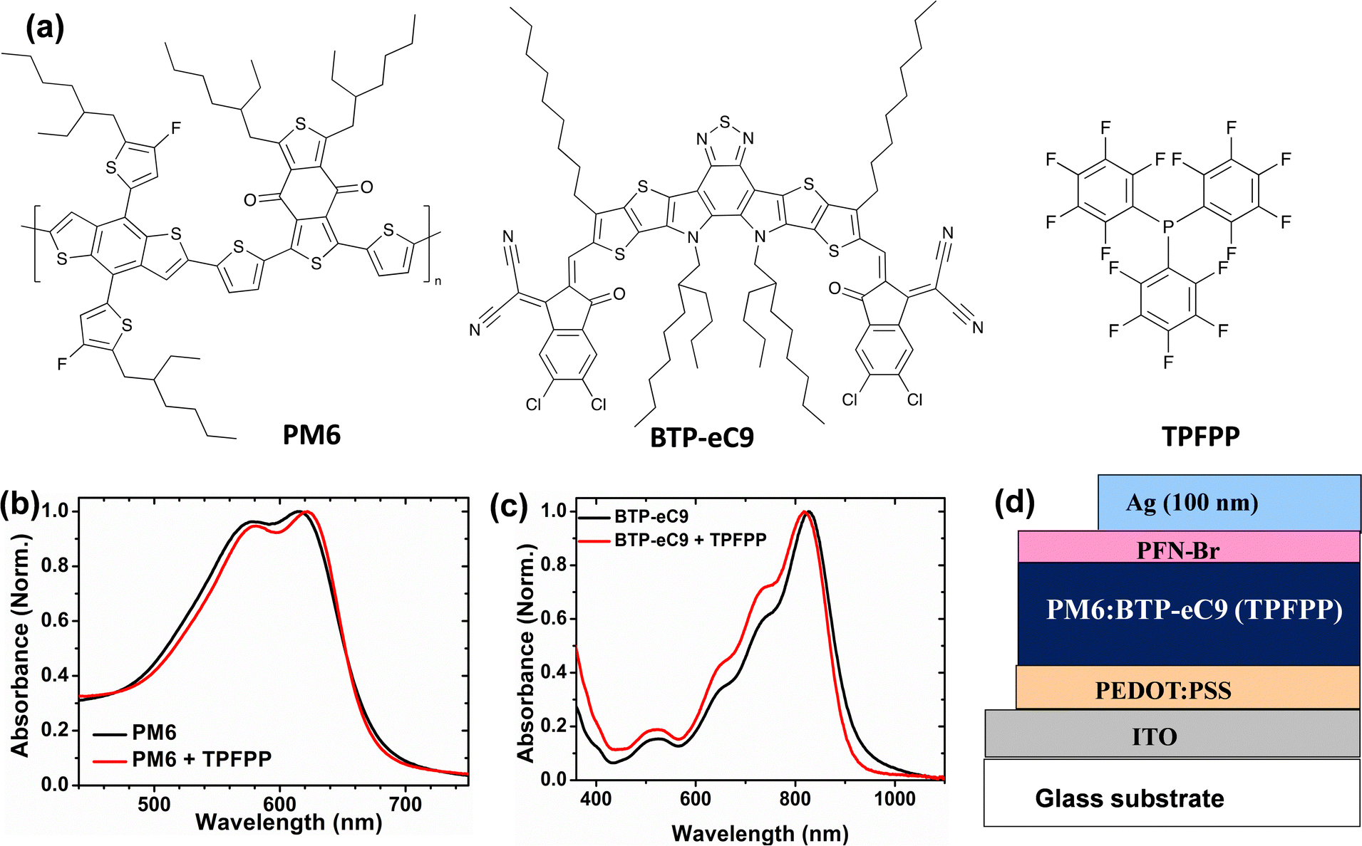 | ||
| Fig. 1 (a) Chemical structures of the polymer PM6, non-fullerene acceptor BTD-eC9 and solid additive TPFPP. (b) Normalized UV–vis absorption spectra of the donor (PM6) and (c) acceptor (BTP-eC9) thin films with and without TPFPP additives. (d) Schematic diagram of the device geometry. | ||
Photovoltaic performance
To investigate the effect of TPFPP additive molecules on the photovoltaic performance, the conventional device geometry of ITO/PEDOT:PSS/PM6:BTP-eC9/PFN-Br/Ag is used as shown in Fig. 1d for device fabrication. A thin layer of poly(9,9-bis(3′-(N,N-dimethyl)-N-ethylammoinium-propyl-2,7-fluorene)-alt-2,7-(9,9-dioctylfluorene))dibromide (PFN-Br) is used as the cathode interlayer. Further information regarding the fabrication and process conditions of OPV devices are given in the ESI.† The current density–voltage (J–V) curves of the device with various TPFPP additive concentrations of the active layer are shown in Fig. 2a, and the device performance parameters are summarised in Table 1. The conventional BHJ OPV device without the TPFPP additive shows a PCE of 15.1% with a short-circuit current density (Jsc) of 24.2 mA cm−2 and a fill factor (FF) of 74%. With the increase of the TPFPP additive content, the PCE of the device improved and achieved a maximum PCE value at 10 mg ml−1 additive content, exhibiting a Voc value of 0.80 V, a Jsc value of 25.7 mA cm−2, a FF value of 80%, and a PCE of 16.9%, which is a significant improvement compared to OPV devices without the TPFPP additive. Further increasing the TPFPP additive to 20 mg ml−1, the performance slightly decreased and achieved a PCE of 15.3%, which is comparable to the control devices without any additives.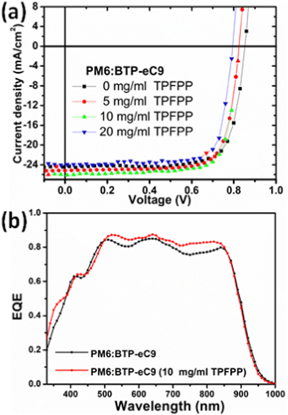 | ||
| Fig. 2 (a) J–V curves and (b) EQE spectra of the OPV devices based on the PM6:BTP-eC9 photoactive layer with and without TPFPP additives. | ||
| Additive concentration | J sc (mA cm−2) | V oc (V) | FF (%) | PCEa (%) (Best cell) |
|---|---|---|---|---|
| a PCE values are calculated using 10 devices. | ||||
| TPFPP (0 mg) | 24.2 ± 0.30 | 0.82 ± 0.02 | 74 ± 2 | 14.90 ± 25 (15.10) |
| TPFPP (5 mg) | 25.3 ± 0.25 | 0.80 ± 0.02 | 78 ± 2 | 16.10 ± 0.25 (16.20) |
| TPFPP (10 mg) | 25.7 ± 0.20 | 0.80 ± 0.02 | 80 ± 2 | 16.80 ± 0.15 (16.90) |
| TPFPP (20 mg) | 24.1 ± 0.30 | 0.78 ± 0.02 | 75 ± 3 | 15.1 ± 0.35 (15.30) |
The observed OPV device performance shows that the TPFPP additive has a significant effect on the OPV device performance, and the performance of solar cells is further characterised by the external quantum efficiency (EQE). As shown in Fig. 2b, the OPV device, without any additive, exhibits an EQE response as high as 83.8%, with a broader photo-response in the wavelength range of 350–930 nm, and this yields an integrated photocurrent of 23.9 mA cm−2, which is consistent with the measured Jsc from the J–V curve (Fig. 2a). With the TPFPP additive, the device exhibits an improved EQE response to 86.9%, which results in the highest Jsc value and contributes to the enhanced integrated photocurrent from 23.9 mA cm−2 to 25.3 mA cm−2. The observed higher EQE response and FF with the TPFPP additive indicate that the carrier dynamics, such as exciton dissociation, charge transport and charge collection of OPV devices, are improved.
Charge transport and exciton generation
To investigate the influence of the TPFPP additive on the charge-transporting properties of the devices, the electron mobility (μe) and hole mobility (μh) were examined by using the space charge limited current (SCLC) method. The configurations of electron-only and hole-only devices are ITO/ZnO/active-layer/PFN-Br/Ag and ITO/PEDOT:PSS/active-layer/MoO3/Ag, respectively, as shown in Fig. S4 (ESI†). As shown in Table S1 (ESI†), the hole mobility and electron mobility of the devices without any additive were 2.62 × 10⁻⁴ cm2 V−1 s−1 and 7.56 × 10⁻⁴ cm2 V−1 s−1, respectively. With the TPFPP additive, the hole mobility was increased to 8.31 × 10⁻⁴ cm2 V−1 s−1, and the electron mobility was improved to 1.88 × 10⁻³ cm2 V−1 s−1. The enhanced charge mobility accounts for the higher Jsc and FF achieved in the TPFPP blended devices, indicating that the device with the additive could achieve more balanced charge transportation by suppressing the accumulation of space charges and decreasing the bimolecular recombination.Next, we investigate the influence of TPFPP additives on exciton dissociation and charge generation behaviour of the OPV devices. As shown in Fig. 4a, the photocurrent (Jph = Jillumination – Jdark) is plotted as a function of the effective voltage (Veff = V0 – V), where Jillumination is the current density under AM 1.5G illumination, Jdark is the dark current density, V0 is the voltage where Jph = 0, and V is the applied bias under AM 1.5G illumination. In both devices, Jph exhibit a linear dependence at low Veff and reaches saturation when the effective voltage (Veff) reached 2 V, suggesting that all devices exhibit negligible recombination at high voltages. At a maximum power output (Veff = 0.2 V), the ratios of Jph/Jsat were calculated as 0.88 and 0.76 for the device with and without the additive, respectively. The larger Jph/Jsat value for the device with the additive could be attributed to efficient charge generation and collection processes compared to devices without TPFPP.
Surface morphology of the active layer
To further probe the influence of solid additives in the morphology of PM6:BTP-eC9 films, tapping mode atomic force microscopy (AFM) was performed to characterise the surface morphology of the active layer films with various concentrations of the TPFPP additive. As shown in Fig. 3, the active layer films show enhanced aggregation morphology with the increased addition of the TPFPP additive, which confirms the interaction of additives with the photoactive layer blend. The optimum morphology was obtained at an additive concentration of 10 mg ml−1, and the corresponding device exhibited an improved Jsc and FF, resulting in the highest efficiency of 16.9%. At a higher additive content (Fig. 3c and d), the surface morphology exhibited excessive holes and clusters due to the evaporation of additives. The average root-mean-square (RMS) roughness increased from 0.75 nm to 4.34 nm for the BHJ film with an additive concentration of 20 mg ml−1. The increased roughness of the surface is an indication of the self-organization of polymer and non-fullerene acceptor domains in the blend, facilitated by solid additives, which in turn enhances the ordered structure orientations in the active layer film, promoting exciton dissociation and charge separation towards respective electrodes. It is well known that morphology optimisation at the nanoscale is crucial for the high performance of OPV devices. Here, the optimum TPFPP additive concentration (10 mg ml−1) improves the nanoscale phase-separated morphology of the photoactive layer, which eventually improves the charge transport leading to balanced transport, reduced recombination and enhanced charge extraction. This optimum nanoscale phase-separated morphology with the TPFPP additive enhances the device performance by improving the Jsc and FF of the device and resulted in the highest efficiency. And our device performance is comparable to earlier reported results of the OPV device with addtives.25–28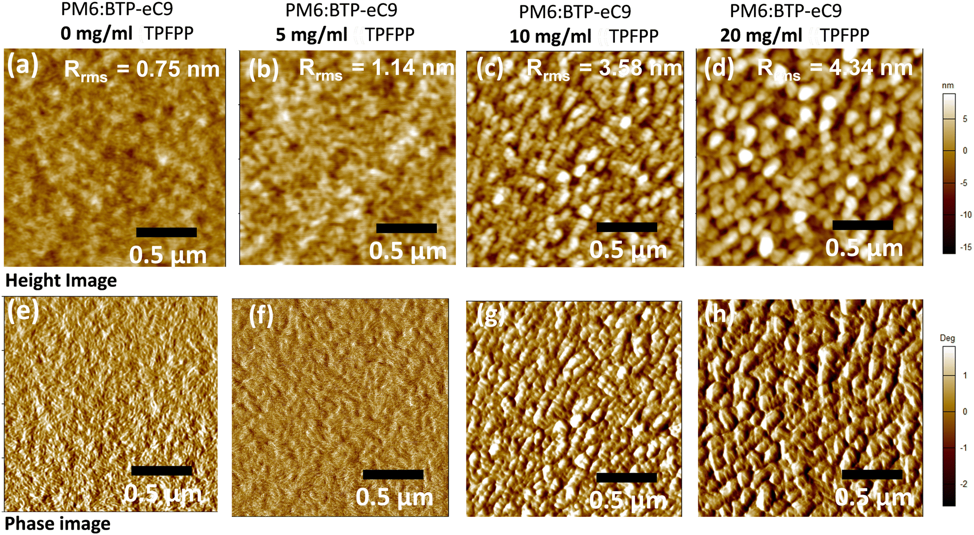 | ||
| Fig. 3 AFM height images (a–d) and phase images (e–h) of blend films based on PM6:BTP-eC9 with various concentrations of TPFPP additives. (The above AFM morphology show that the nanoscale phase separated domain size increases with the increasing additive concentration.) | ||
Next, to investigate the molecular interaction of TPFPP with the active layer blend, ATR-FTIR measurements were performed on the active layer blend films with and without TPFPP additives processed at RT and under thermal annealing (100 °C) conditions (Fig. 4b). It is known that the halogen atom in TPFPP can interact with active layer molecules containing S, N or O atoms through the formation of fluorine bonding.35 As shown in Fig. 4b, the peaks at 1430 and 1650 cm−1 are assigned to the C–C and C = 0 stretching. The ATR-FTIR spectra of films without TPFPP and with TPFPP processed at 100 °C are identical, confirming the removal of solid additives upon thermal annealing. The blend film with TPFPP additives processed without annealing exhibits a peak shift from 1650 to 1640 cm−1 and 1540 to 1530 cm−1, suggesting the interaction of TPFPP with the photoactive layer.
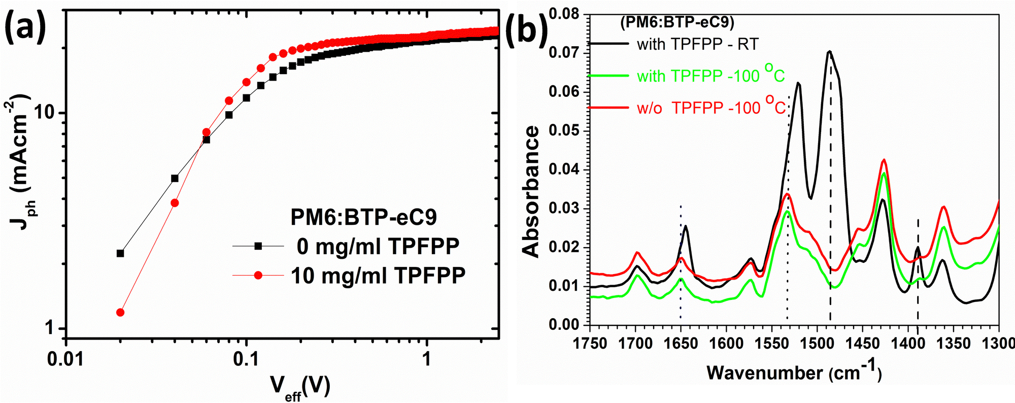 | ||
| Fig. 4 (a) Jphvs. Veff characteristics of the devices and (b) ATR-FTIR spectra of PM6:BTP-eC9 films with and without TPFPP additives. | ||
XPS studies of the active layer
In order to confirm the volatility of the TPFPP additive from the active layer upon annealing at 100 °C, X-ray photoelectron spectroscopy (XPS) measurement and XPS depth-profile analysis were performed.38 As shown in Fig. 5a and b, the high-resolution XPS spectra of F1s and P2p elements showed the absence of TPFPP additives in both annealed and non-annealed films, and this observation confirms that there is no TPFPP additive on the surface of the film. To further confirm whether TPPFF molecules are present inside the active layer, we probe the photo-active layer with TPFPP additives, using XPS-depth profile analysis. In this study, the chemical composition, such as F1s, C1s, Cl2p, S2p, P2p and In3d, of the active layer film coated on top of ITO/PEDOT:PSS was analysed using XPS in conjunction with Ar–ion beam sputtering. Here, we analyse the TPFPP added active layer film with XPS for every 10 s of argon ion beam etching, and the active layer etching time was calibrated to the thickness of the active layer as shown in Fig. 5c and d. In the active layer, both the PM6 polymer and the TPFPP molecule have fluorine atoms. It was expected that, if TPFPP additives resided in the active layer, the XPS analysis should exhibit a more intense F1s peak for the non-annealed film compared to that for the annealed active layer. However, we observed no change in the F1s peak intensity (Fig. 5a), which confirms the volatility of TPFPP additives. In addition, the XPS depth profile plot (Fig. 5d) shows the atomic percentage of the F1s signal is just half of the Cl2p signal, which is a characteristic peak of the BTP-ec9 acceptor, confirming the presence of only PM6 and BTP-ec9 in the film rather than TPFPP additives. As shown in Fig. 5b and d, both high-resolution XPS and depth profile analysis confirm the absence of a phosphorous P2p signal in both the annealed and non-annealed films, which further confirms the evaporation of TPFPP additives upon annealing. However, the absence of a P2p signal in the non-annealed film (Fig. 5b) might be due to the removal of volatile additives during the ultra-high vacuum process in XPS characterisation.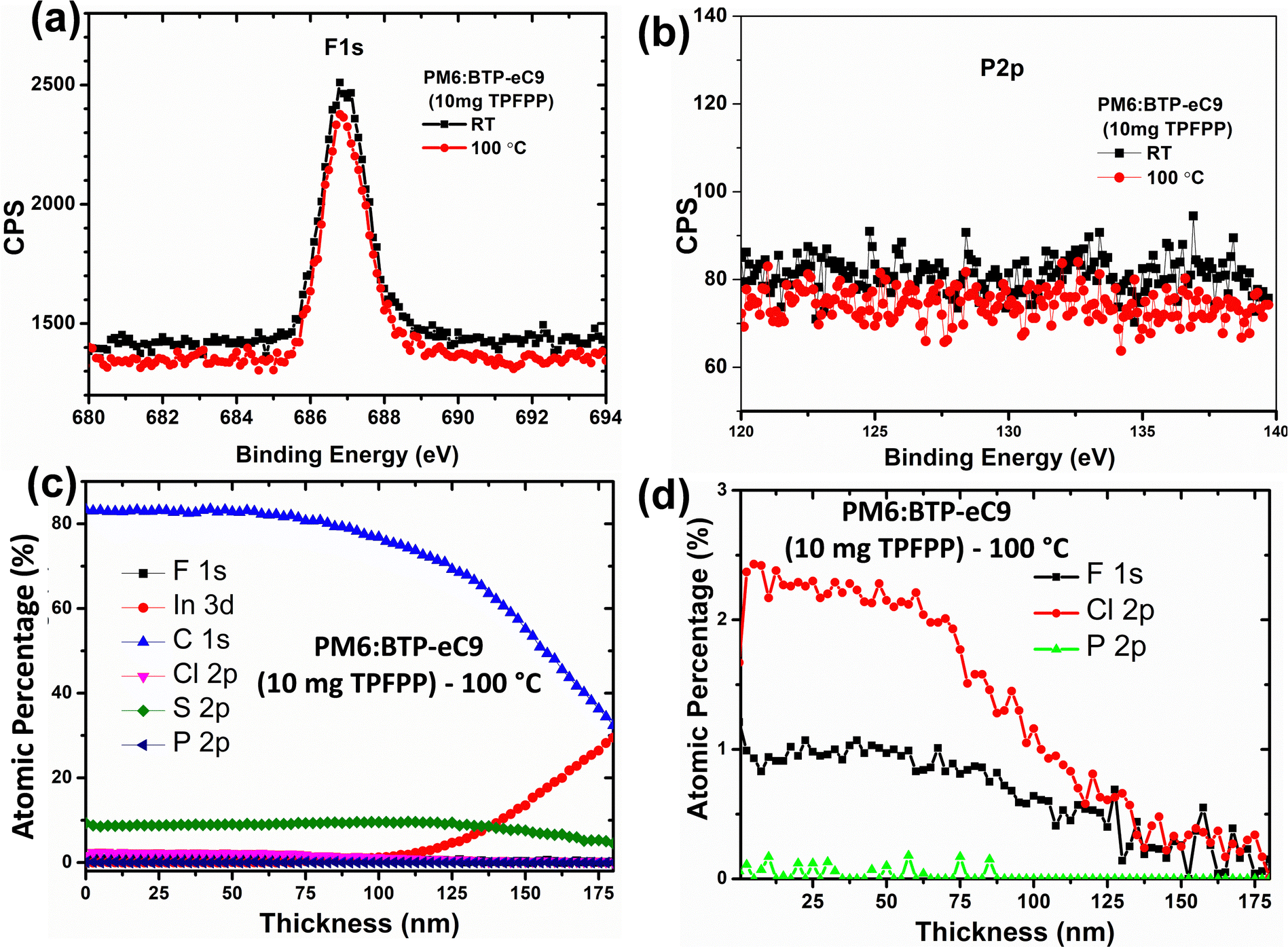 | ||
| Fig. 5 2D high-resolution XPS spectra of (a) F1s and (b) P2p. (c) and (d) XPS-depth profile analysis of the active layer with 10 mg of TPFPP upon annealing. | ||
Conclusions
In conclusion, we have successfully demonstrated a novel solid additive TPFPP to control the BHJ morphology and enhance the device performance of non-fullerene OSCs based on PM6:BTP-eC9. The OPV device with the TPFPP additive achieved a higher PCE of 16.9% and an FF of 80% due to the improved nanoscale morphology, and enhanced charge extraction, and charge transport properties. Further analysis of the active layer confirms that the intermolecular interaction of additives with the active layer fine tunes the nanoscale morphology of the active layer. The volatility of TPFPP additives upon thermal annealing was characterised using optical studies and XPS depth profile analysis. Our observations reveal the great potential of phosphorous-based fluorinated solid additives for boosting the OPV device efficiency and large-area device fabrication for high-performance devices.Conflicts of interest
There are no conflicts to declare.Acknowledgements
JS and DJJ are funded by the Australian Government through the Australian Renewable Energy Agency (ARENA) and Australian Centre for Advanced Photovoltaics (ACAP). The Australian Government does not accept responsibility for the views, information or advice expressed herein. The authors acknowledge the facilities and the technical assistance of the RMIT University Microscopy and Microanalysis Facility (RMMF). This work was performed in part at the Materials Characterisation and Fabrication Platform (MCFP) at the University of Melbourne. The authors also acknowledge Flexible Electronics Lab, CSIRO, Clayton, for device fabrication and characterisation facilities.References
- P. Cheng, G. Li, X. Zhan and Y. Yang, Nat. Photonics, 2018, 12, 131–142 CrossRef CAS.
- L. W. T. Ng, S. W. Lee, D. W. Chang, J. M. Hodgkiss and D. Vak, Adv. Mater. Technol., 2022, 7, 2101556 CrossRef.
- L. Lu, T. Zheng, Q. Wu, A. M. Schneider, D. Zhao and L. Yu, Chem. Rev., 2015, 115, 12666–12731 CrossRef CAS PubMed.
- Y.-J. Heo, J.-E. Kim, H. Weerasinghe, D. Angmo, T. Qin, K. Sears, K. Hwang, Y.-S. Jung, J. Subbiah, D. J. Jones, M. Gao, D.-Y. Kim and D. Vak, Nano Energy, 2017, 41, 443–451 CrossRef CAS.
- Y. Cui, Y. Xu, H. Yao, P. Bi, L. Hong, J. Zhang, Y. Zu, T. Zhang, J. Qin, J. Ren, Z. Chen, C. He, X. Hao, Z. Wei and J. Hou, Adv. Mater., 2021, 33, 2102420 CrossRef CAS PubMed.
- Q. Liu, Y. Jiang, K. Jin, J. Qin, J. Xu, W. Li, J. Xiong, J. Liu, Z. Xiao, K. Sun, S. Yang, X. Zhang and L. Ding, Sci. Bull., 2020, 65, 272 CrossRef CAS PubMed.
- C. He, Z. Chen, T. Wang, Z. Shen, Y. Li, J. Zhou, J. Yu, H. Fang, Y. Li, S. Li, X. Lu, W. Ma, F. Gao, Z. Xie, V. Coropceanu, H. Zhu, J.-L. Bredas, L. Zuo and H. Chen, Nat. Commun., 2022, 13, 2598 CrossRef CAS PubMed.
- Y. Wei, Z. Chen, G. Lu, N. Yu, C. Li, J. Gao, X. Gu, X. Hao, G. Lu, Z. Tang, J. Zhang, Z. Wei, X. Zhang and H. Huang, Adv. Mater., 2022, 34, 2204718 CrossRef CAS PubMed.
- C. Lee, S. Lee, G.-U. Kim, W. Lee and B. J. Kim, Chem. Rev., 2019, 119, 8028–8086 CrossRef CAS PubMed.
- J. Subbiah, C. J. Lee, V. D. Mitchell and D. J. Jones, ACS Appl. Mater. Interfaces, 2021, 13, 1086–1093 CrossRef CAS PubMed.
- L. Zhu, M. Zhang, J. Xu, C. Li, J. Yan, G. Zhou, W. Zhong, T. Hao, J. Song, X. Xue, Z. Zhou, R. Zeng, H. Zhu, C.-C. Chen, R. C. I. MacKenzie, Y. Zou, J. Nelson, Y. Zhang, Y. Sun and F. Liu, Nat. Mater., 2022, 21, 656–663 CrossRef CAS PubMed.
- K. Sun, Z. Xiao, S. Lu, W. Zajaczkowski, W. Pisula, E. Hanssen, J. M. White, R. M. Williamson, J. Subbiah, J. Ouyang, A. B. Holmes, W. W. H. Wong and D. J. Jones, Nat. Commun., 2015, 6, 6013 CrossRef CAS PubMed.
- C. E. Small, S. Chen, J. Subbiah, C. M. Amb, S.-W. Tsang, T.-H. Lai, J. R. Reynolds and F. So, Nat. Photonics, 2012, 6, 115–120 CrossRef CAS.
- C. J. Lee, V. D. Mitchell, J. White, X. Jiao, C. R. McNeill, J. Subbiah and D. J. Jones, J. Mater. Chem. A, 2019, 7, 6312–6326 RSC.
- C. McDowell, M. Abdelsamie, M. F. Toney and G. C. Bazan, Adv. Mater., 2018, 30, 1707114 CrossRef PubMed.
- R. Datt, Suman, A. Bagui, A. Siddiqui, R. Sharma, V. Gupta, S. Yoo, S. Kumar and S. P. Singh, Sci. Rep., 2019, 9, 8529 CrossRef PubMed.
- J. Qin, Q. Yang, J. Oh, S. Chen, G. O. Odunmbaku, N. A. N. Ouedraogo, C. Yang, K. Sun and S. Lu, Adv. Sci., 2022, 9, 2105347 CrossRef CAS PubMed.
- L. Guo, Q. Li, J. Ren, Y. Xu, J. Zhang, K. Zhang, Y. Cai, S. Liu and F. Huang, Energy Environ. Sci., 2022, 15, 5137–5148 RSC.
- C. M. Amb, S. Chen, K. R. Graham, J. Subbiah, C. E. Small, F. So and J. R. Reynolds, J. Am. Chem. Soc., 2011, 133, 10062–10065 CrossRef CAS PubMed.
- H. Choi, S.-J. Ko, T. Kim, P.-O. Morin, B. Walker, B. H. Lee, M. Leclerc, J. Y. Kim and A. J. Heeger, Adv. Mater., 2015, 27, 3318–3324 CrossRef CAS PubMed.
- C. V. Hoven, X.-D. Dang, R. C. Coffin, J. Peet, T.-Q. Nguyen and G. C. Bazan, Adv. Mater., 2010, 22, E63–E66 CrossRef CAS PubMed.
- B. J. Tremolet de Villers, K. A. O’Hara, D. P. Ostrowski, P. H. Biddle, S. E. Shaheen, M. L. Chabinyc, D. C. Olson and N. Kopidakis, Chem. Mater., 2016, 28, 876–884 CrossRef CAS.
- A. Tournebize, A. Rivaton, H. Peisert and T. Chassé, J. Phys. Chem. C, 2015, 119, 9142–9148 CrossRef CAS.
- D. Hu, Q. Chen, J. Zhang and S. Lu, Sustainable Energy Fuels, 2022, 6, 5256–5260 RSC.
- Y.-F. Ma, Y. Zhang and H.-L. Zhang, J. Mater. Chem. C, 2022, 10, 2364–2374 RSC.
- S. Bao, H. Yang, H. Fan, J. Zhang, Z. Wei, C. Cui and Y. Li, Adv. Mater., 2021, 33, 2105301 CrossRef CAS PubMed.
- Q. Yu, J. Fu, H. Chen, S. Chen, D. Hu, K. Yang, Z. Kan, K. Sun, S. Lu and Z. Xiao, Org. Electron., 2021, 93, 106161 CrossRef CAS.
- J. Fu, H. Chen, P. Huang, Q. Yu, H. Tang, S. Chen, S. Jung, K. Sun, C. Yang, S. Lu, Z. Kan, Z. Xiao and G. Li, Nano Energy, 2021, 84, 105862 CrossRef CAS.
- R. Yu, H. Yao, L. Hong, Y. Qin, J. Zhu, Y. Cui, S. Li and J. Hou, Nat. Commun., 2018, 9, 4645 CrossRef PubMed.
- R. Yu, H. Yao, Z. Chen, J. Xin, L. Hong, Y. Xu, Y. Zu, W. Ma and J. Hou, Adv. Mater., 2019, 31, 1900477 CrossRef PubMed.
- J. Cai, H. Wang, X. Zhang, W. Li, D. Li, Y. Mao, B. Du, M. Chen, Y. Zhuang, D. Liu, H.-L. Qin, Y. Zhao, J. A. Smith, R. C. Kilbride, A. J. Parnell, R. A. L. Jones, D. G. Lidzey and T. Wang, J. Mater. Chem. A, 2020, 8, 4230–4238 RSC.
- Z. Yang, J. Dou, S. Kou, J. Dang, Y. Ji, G. Yang, W.-Q. Wu, D.-B. Kuang and M. Wang, Adv. Funct. Mater., 2020, 30, 1910710 CrossRef CAS.
- T. Korenaga, A. Ko, K. Uotani, Y. Tanaka and T. Sakai, Angew. Chem., Int. Ed., 2011, 50, 10703–10707 CrossRef CAS PubMed.
- M. Xu, Y. Liu, B. Li, W. Li, X. Li and S. Hu, Electrochem. Commun., 2012, 18, 123–126 CrossRef CAS.
- J. Fu, S. Chen, K. Yang, S. Jung, J. Lv, L. Lan, H. Chen, D. Hu, Q. Yang, T. Duan, Z. Kan, C. Yang, K. Sun, S. Lu, Z. Xiao and Y. Li, iScience, 2020, 23, 100965 CrossRef CAS PubMed.
- K. Eskandari and M. Lesani, Chem. – Eur. J., 2015, 21, 4739–4746 CrossRef CAS PubMed.
- W. Li, M. Chen, J. Cai, E. L. K. Spooner, H. Zhang, R. S. Gurney, D. Liu, Z. Xiao, D. G. Lidzey, L. Ding and T. Wang, Joule, 2019, 3, 819–833 CrossRef CAS.
- J. Subbiah, C. M. Amb, J. R. Reynolds and F. So, Sol. Energy Mater. Sol. Cells, 2012, 97, 97–101 CrossRef CAS.
Footnote |
| † Electronic supplementary information (ESI) available. See DOI: https://doi.org/10.1039/d3ma00106g |
| This journal is © The Royal Society of Chemistry 2023 |