
 Open Access Article
 This Open Access Article is licensed under a
 Creative Commons Attribution 3.0 Unported Licence
Eco-friendly Egyptian blue (CaCuSi4O10) dye for luminescent solar concentrator applications
Tharmakularasa
Rajaramanan
 ac,
Mansoureh
Keykhaei
a,
Fatemeh Heidari
Gourji
a,
Punniamoorthy
Ravirajan
c,
Meena
Senthilnanthanan
d,
Øyvind
Frette
b and
Dhayalan
Velauthapillai
*a
ac,
Mansoureh
Keykhaei
a,
Fatemeh Heidari
Gourji
a,
Punniamoorthy
Ravirajan
c,
Meena
Senthilnanthanan
d,
Øyvind
Frette
b and
Dhayalan
Velauthapillai
*a
aFaculty of Engineering and Science, Western Norway University of Applied Sciences, P.O. Box 7030, 5020 Bergen, Norway. E-mail: Dhayalan.Velauthapillai@hvl.no
bDepartment of Physics and Technology, University of Bergen, Allegaten 55, 5007 Bergen, Norway
cClean Energy Research Laboratory, Department of Physics, University of Jaffna, Jaffna 40000, Sri Lanka
dDepartment of Chemistry, University of Jaffna, Jaffna 40000, Sri Lanka
First published on 14th April 2023
Abstract
This study focuses on synthesizing the heavy metal-free ancient Egyptian blue (EB; CaCuSi4O10) dye using a facile ceramic method for luminescent solar concentrator (LSC) application. XRD, SEM and EDX results confirmed that this well-crystallized material is successfully synthesized. Optical studies revealed that EB has a high Stokes shift and possesses an average lifetime of 110.50 μs with a quantum yield of 12.93%. Finally, an EB-integrated LSC was fabricated that exhibits a power conversion efficiency (η) of 0.15% and an optical conversion efficiency (ηopt) of 1.21%, which are the highest values reported so far using EB.
1. Introduction
One of the constraints with electricity production using conventional Si-based solar cells is the amount of area that is needed for roof-top or stand-alone installations.1 The lack of flexibility and weight are other challenges that must be addressed to ensure affordable energy for all (i.e., Sustainable Development Goal 7) based on solar cell technologies.2 Lots of research into solar cells has been focused on novel materials and new processes for solar cell fabrication. Luminescent solar concentrators (LSCs) have been explored as a potential solution to tackle the aforementioned limitations. A typical LSC consists of a transparent glass plate, which is coated with a highly luminescent material that absorbs solar radiation. These materials then re-emit the absorbed photons at long wavelengths which are transported to the edges of the LSCs that are coupled with the solar cell, thus producing electricity.3,4 LSCs serving as semitransparent photovoltaic windows could become an important element in net-zero-energy-consumption buildings of the future.5 Such laminated glass offers benefits towards security, soundproofing and energy conservation through the building of windows, facades, and transparent roofs.6,7 In addition, an LSC does not require solar tracking and can operate in both diffuse and direct sunlight.6 Nevertheless, LSC development faces various challenges, many of which are related to the materials used in its design. Luminescent materials can be either organic or inorganic.8–11 The major inorganic luminescent materials are quantum dots (QDs) and rare-earth (RE)-based luminescent materials, where each type possesses its own benefits and drawbacks, making neither of them an ideal LSC candidate.12 Organic luminescent dyes typically suffer from large self-absorption losses (a large overlap between the absorption and emission spectra), poor stability, narrow-band absorbance, and a lack of spectral matching with the peak external quantum efficiency (EQE) of the solar cells.Egyptian blue (EB) is a luminescent material that is also called cuprorivaite (CaCuSi4O10). It is a copper-based dye and can overcome the limitations of toxicity and cost-related issues that are seen with other luminescent materials.
It has superior stability and was produced by ancient chemists as a pigment (Fig. 1), which shows luminescent abilities even after several thousand years.13 Moreover, it is a red-light-emitting phosphorescent substance, which shows the highest quantum efficiency in the near-infrared (NIR) spectral range (800–1100 nm). The Stokes shift for this material is as high as 280 nm, which minimizes re-absorption events.14 In addition, silicon solar cells have the ability to absorb in the NIR range at wavelengths around 1000 nm; however, the solar spectrum itself shows a deficiency at such wavelengths after the radiation has passed through the atmosphere.15 Considering all these factors, we have developed a novel, efficient and cost effective LSC based on a stable and non-toxic artificial pigment with a PL peak at ∼900 nm, which matches well with the peak EQE of crystalline silicon (c-Si) solar cells (∼850–950 nm).
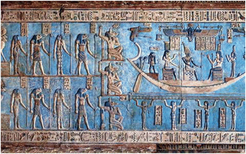 | ||
| Fig. 1 Ancient painting in ceiling reliefs in the Hathor Temple in Qena, Egypt (Source: https://www.chemistryworld.com/features/egyptian-blue-more-than-just-a-colour/9001.article) | ||
2. Materials and method
The CaCuSi4O10 dye was synthesized using a modified procedure adopted from elsewhere.14 CaCO3 (0.66 g, 99+%, Acros Organics), SiO2 (1.59 g, 99.5%, Alfa Aesar), Cu2CO3 (0.73 g, 54–56% Cu, Acros Organics), Na2CO3 (0.18 g, 99.95%, Acros Organics), NaCl (0.06 g, ≥99.0%, Sigma-Aldrich), and Na2B4O7 (0.125 g, anhydrous powder, Alfa Aesar) were ground well using mortar and pestle to form a homogeneous mixture. Then, the mixture was transferred into a ceramic dish and heated at a high temperature of around 900 °C for 16 hours in a muffle furnace. After cooling to room temperature, the product was washed with aqueous HCl (HCl![[thin space (1/6-em)]](https://www.rsc.org/images/entities/char_2009.gif) :H2O = 70:30) to get rid of residues. Finally, the product was washed several times with DI-water to remove the acid, and subsequently dried at 60 °C overnight in an oven (Fig. 2). The synthesized CaCuSi4O10 and polyvinylpyrrolidone (a binder; average MW 3500, K12, Acros Organics) were mixed well using a mortar and pestle. Then, the mixture was dispersed in 20 mL of ethanol solvent. Finally, the dispersed mixture was coated onto a quartz glass surface at 100 °C on a hot plate via spray coating.
:H2O = 70:30) to get rid of residues. Finally, the product was washed several times with DI-water to remove the acid, and subsequently dried at 60 °C overnight in an oven (Fig. 2). The synthesized CaCuSi4O10 and polyvinylpyrrolidone (a binder; average MW 3500, K12, Acros Organics) were mixed well using a mortar and pestle. Then, the mixture was dispersed in 20 mL of ethanol solvent. Finally, the dispersed mixture was coated onto a quartz glass surface at 100 °C on a hot plate via spray coating.
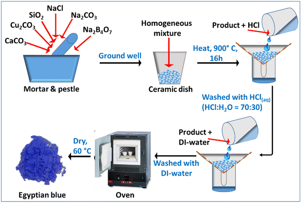 | ||
| Fig. 2 Schematic diagram of the synthesis of Egyptian blue. | ||
3. Results and discussion
3.1. Structural characterization of Egyptian blue
XRD measurements were carried out to confirm the crystal structure of the Egyptian blue using a D8 ADVANCE ECO diffractometer with a 1 kW copper X-ray tube with the scan range of 10–90° (2θ). As displayed in Fig. 3a, significant sharp peaks of cuprorivaite (CaCuSi4O10) were detected along with a small amount of quartz.16 The presence of the quartz (SiO2) impurity could be attributed to the un-reacted SiO2 precursor. All of the observed major peaks matched very well with the literature, confirming the formation of the target material. The morphology and elemental composition of the prepared material were studied using a scanning electron microscope (FESEM, Jeol JSM-7400F) along with an energy-dispersive X-ray spectrometer (EDX). Prior to the analysis, the material was ground well using a mortar and pestle to form a smooth powder. The results show that many of the particles possess irregular shapes of 1–10 μm size while some are in the nano size range (Fig. 3b). The EDX spectra (Fig. 3c) showed clear peaks for calcium, copper, silicon, and oxygen elements, which confirmed the structure of EB. Furthermore, EDX mapping illustrated the extensive dispersion of the elements in the material, which suggests that all the elements are uniformly distributed in the synthesized material (Fig. 3d).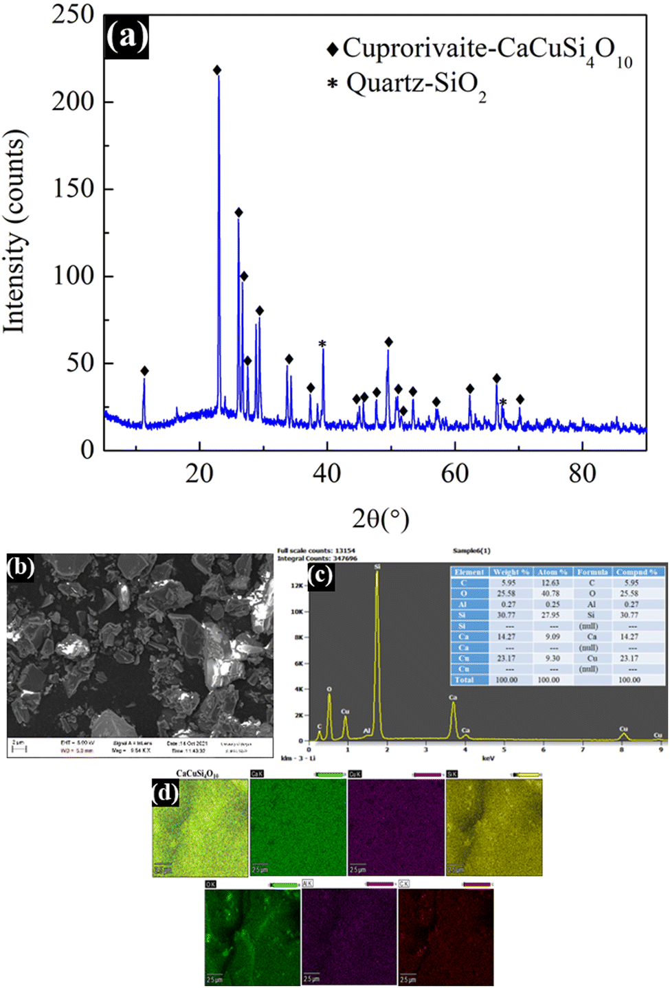 | ||
| Fig. 3 XRD (a), SEM (b), EDX (c), and EDX mapping (d) images of the synthesized Egyptian blue. | ||
3.2. Optical characterization of Egyptian blue
The optical properties of the material were thoroughly studied using an FS5 spectrofluorometer. The PL excitation and emission spectra were measured in the spectral range from 400 to 1000 nm. As illustrated in Fig. 4a, the maximum PL excitation, monitored at 635 nm, corresponding to the 2B1g → 2B2g and 2Eg → 2A1g electronic transitions can be attributed to Cu2+ ions, which are the photoluminescent component in the EB. The maximum emission displayed at 909 nm is related to the 2B2g → 2B1g electronic transition.17 Moreover, EB possesses a large Stokes shift, due to which re-absorption losses are minimized, and the emission at 909 nm matches well with the photo-responsive region of silicon solar cells; all these observations make this dye well-suited for LSC application. The PL decay curve in Fig. 4b does not match well with a single exponential decay; hence, a bi-exponential decay curve fitting method was employed. The obtained results are T1 = 53.53 μs, T2 = 150.68 μs and X2 = 1.070.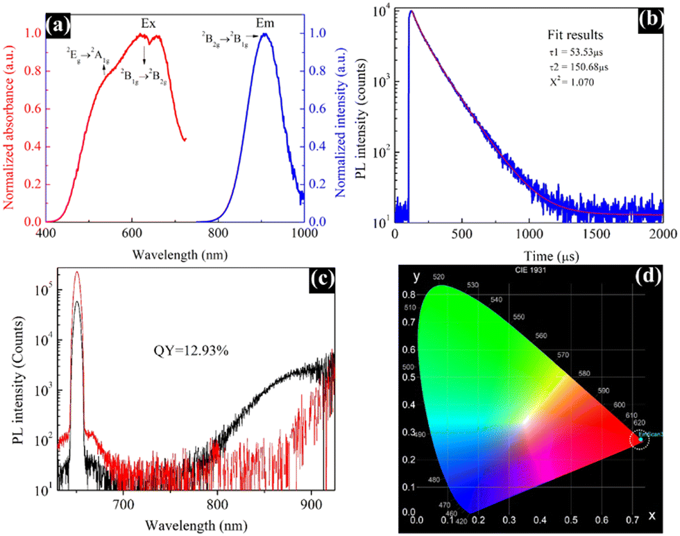 | ||
| Fig. 4 PL excitation and emission spectra (a), PL decay curve (b), PL quantum yield measurement (c), and CIE chromaticity diagram (d) of the Egyptian blue. | ||
Moreover, the EB dye showed an average lifetime of 110.50 μs. Earlier, Comelli et al. reported mono-exponential decay kinetics with a lifetime of 138 μs for EB, which is reasonably similar to our findings.18 The PL quantum yield measurements are displayed in Fig. 4c, which were obtained during the excitation and luminescence ranges of 640–660 and 798–914 nm, respectively. The synthesized EB dye exhibited a quantum yield of 12.93%, which is the highest value ever reported for the EB dye obtained via different synthetic routes.14,17 Generally, the luminescence colour of any phosphorescent material can be illustrated using colour coordinates. Fig. 4d shows the CIE (Commission international de l’éclairage) chromaticity image of the EB dye. The synthesized material exhibited a maximum emission intensity with the CIE colour coordinates of (0.72, 0.27), which is close to the National Television System Committee (NTSC) red colour19 as it is a red-emitting phosphorescent material.
3.3. Photovoltaic properties of an Egyptian blue-integrated luminescent solar concentrator
Fig. 5a displays the fabricated LSC integrated with the synthesized blue pigment dye, and Fig. 5b depicts the UV-vis transmittance spectrum of the same LSC plate, where the transmittance of the EB-coated LSC plate is compared with a bare (un-coated) quartz plate as a reference. This spectrum reveals that the glass is still transparent even after being coated with EB. The PV performance of the EB-coated LSC was analyzed, where a commercial silicon solar cell with an area of 4.0 cm2 was edged onto the said LSC, and the results are shown in Fig. 5c and d. Solar cells of the same size were employed to record the measurements, and the I–V measurements were obtained under a light intensity of 1 Sun illumination using an AM 1.5G filter. All measurements were performed using a dark background, without the use of a reflective mirror/foil or a scattering background to reflect the photons that are emitted outside the escape cone back into the waveguide for recycling.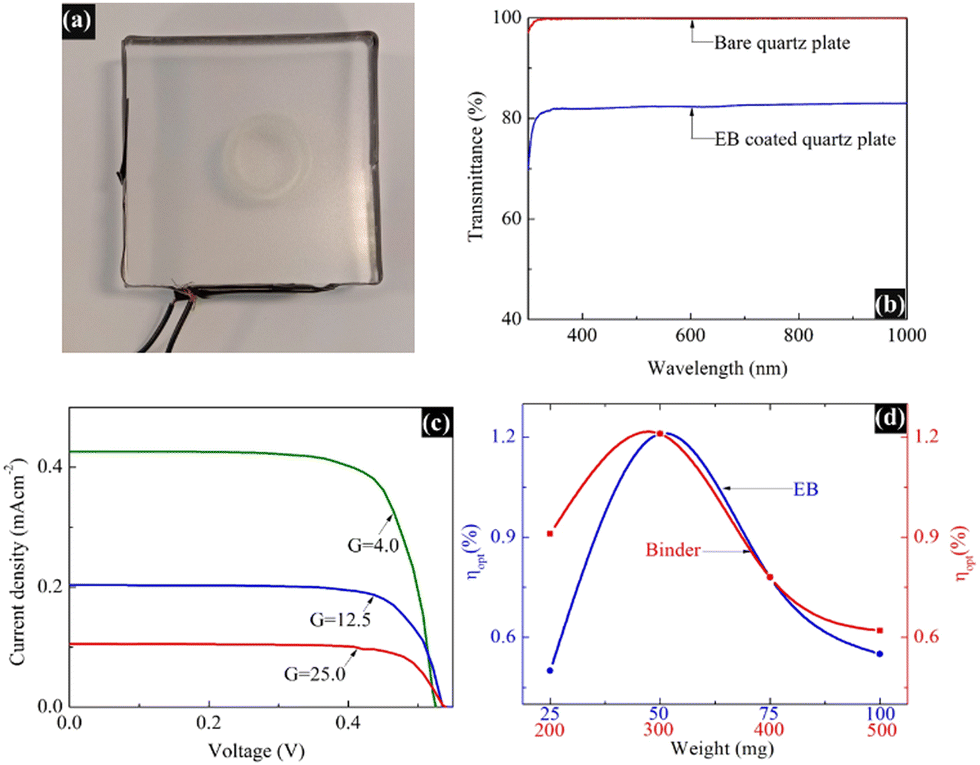 | ||
| Fig. 5 Fabricated luminescent solar concentrator (10 × 10) integrated with Egyptian blue (a), UV-vis transmittance spectrum of the same LSC plate (b), photovoltaic performance of the LSC with different G factor values (EB, 50 mg; binder, 300 mg) (c), and variation of the optical efficiency with different amounts of EB (blue line, where 300 mg of binder was used and G = 4) and binder (red line, where 50 mg of EB was used and G = 4) (d). | ||
The power conversion efficiency (η) of the fabricated LSC was calculated using the following equation,3 and the results are summarized in Table 1:
| PCE (η) = ILSC × VOC × FF/(P × ALSC) |
| I LSC (mA) | A LSC (cm2) | J LSC (mA cm−2) | V OC (V) | FF | η (%) | G | η opt (%) |
|---|---|---|---|---|---|---|---|
| 6.8 | 16 | 0.43 | 0.52 | 0.74 | 0.15 | 4.0 | 1.21 |
| 9.9 | 49 | 0.20 | 0.53 | 0.74 | 0.07 | 12.5 | 0.56 |
| 10.0 | 100 | 0.10 | 0.53 | 0.74 | 0.04 | 25.0 | 0.28 |
The optical conversion efficiency (ηopt) of the fabricated LSC was calculated using the following equation:
| ηopt = ILSC/(Icell × G) |
Furthermore, the practical application of the fabricated LSC was demonstrated by connecting the device to a mini-sized electric table fan (Fig. 6).
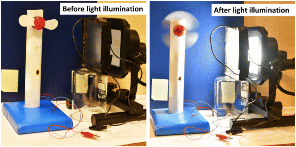 | ||
| Fig. 6 Working model of the fabricated luminescent solar concentrator. | ||
4. Conclusion
In this study, a novel method to fabricate LSCs using the ancient Egyptian blue dye (CaCuSi4O10) has been established. The EB dye was synthesized successfully using a facile ceramic method, and its formation was confirmed via XRD, SEM and EDX measurements. The dye exhibited PL excitation and emission maxima at 635 and 909 nm, respectively. The time-resolved PL decay spectrum showed bi-exponential emission behavior with an average lifetime of 110.50 μs. Moreover, it possessed a quantum yield of 12.93%. The EB dye-incorporated LSC exhibited an impressive η and ηopt of 0.15% and 1.21%, respectively. The above findings suggest that the EB dye can be a suitable material for integration with LSCs for industrial applications.Author contributions
Tharmakularasa Rajaramanan: conceptualization, methodology, data curation, software, writing – original draft preparation. Mansoureh Keykhaei: conceptualization, methodology, data curation, reviewing and editing. Fatemeh Heidari Gourji: data curation, investigation, reviewing and editing. Punniamoorthy Ravirajan: data curation, investigation, validation, supervision, funding acquisition, reviewing and editing. Meena Senthilnanthanan: data curation, investigation, validation, supervision, reviewing and editing. Øyvind Frette: data curation, investigation, supervision. Dhayalan Velauthapillai: data curation, investigation, validation, supervision, visualization, funding acquisition, reviewing and editing.Conflicts of interest
There are no conflicts to declare.Acknowledgements
This research was funded by the Capacity Building and Establishment of a Research Consortium (CBERC) project, grant number LKA-3182-HRNCET and the Higher Education and Research collaboration on Nanomaterials for Clean Energy Technologies (HRNCET) project, grant number NORPART/2016/10,237. Open access funding provided by Western Norway University Of Applied Sciences.References
- T. Rajaramanan, G. R. A. Kumara, D. Velauthapillai, P. Ravirajan and M. Senthilnanthanan, Mater. Sci. Semicond. Process., 2021, 135, 106062 CrossRef CAS.
- D. McCollum, L. Gomez Echeverri, K. Riahi and S. Parkinson, SDG 7: ensure access to affordable, reliable, sustainable and modern energy for all, A Guide to SDG Interactions: From Science to Implementation, International Council for Science, International Council for Science, 2017, pp. 127–173 Search PubMed.
- Z. Li, X. Zhao, C. Huang and X. Gong, J. Mater. Chem. C, 2019, 7, 12373–12387 RSC.
- M. Cao, X. Zhao and X. Gong, JACS Au, 2023, 3, 25–35 CrossRef CAS PubMed.
- F. Meinardi, H. McDaniel, F. Carulli, A. Colombo, K. A. Velizhanin, N. S. Makarov, R. Simonutti, V. I. Klimov and S. Brovelli, Nat. Nanotechnol., 2015, 10, 878–885 CrossRef CAS PubMed.
- M. K. Assadi, H. Hanaei, N. M. Mohamed, R. Saidur, S. Bakhoda, R. Bashiri and M. Moayedfar, Appl. Phys. A: Mater. Sci. Process., 2016, 122, 821 CrossRef.
- J. Levitt and W. Weber, Appl. Opt., 1977, 16, 2684–2689 CrossRef CAS PubMed.
- J. Chen, H. Zhao, Z. Li, X. Zhao and X. Gong, Energy Environ. Sci., 2022, 15, 799–805 RSC.
- X. Gong, H. Jiang, M. Cao, Z. Rao, X. Zhao and A. Vomiero, Mater. Chem. Front., 2021, 5, 4746–4755 RSC.
- X. Gong, S. Zheng, X. Zhao and A. Vomiero, Nano Energy, 2022, 101, 107617 CrossRef CAS.
- J. Li, H. Zhao, X. Zhao and X. Gong, Nanoscale Horiz., 2023, 8, 83–94 RSC.
- W. G. Van Sark, K. W. Barnham, L. H. Slooff, A. J. Chatten, A. Büchtemann, A. Meyer, S. J. McCormack, R. Koole, D. J. Farrell and R. Bose, Opt. Express, 2008, 16, 21773–21792 CrossRef CAS PubMed.
- P. García-Fernández, M. Moreno and J. A. Aramburu, Inorg. Chem., 2015, 54, 192–199 CrossRef PubMed.
- P. Sobik, O. Jeremiasz, P. Nowak, A. Sala, B. Pawłowski, G. Kulesza-Matlak, A. Sypień and K. Drabczyk, Materials, 2021, 14, 3952 CrossRef CAS PubMed.
- R. Santbergen and R. C. van Zolingen, Sol. Energy Mater. Sol. Cells, 2008, 92, 432–444 CrossRef CAS.
- O. Ormanci, Spectrochim. Acta, Part A, 2020, 229, 117889 CrossRef CAS PubMed.
- G. Accorsi, G. Verri, M. Bolognesi, N. Armaroli, C. Clementi, C. Miliani and A. Romani, Chem. Commun., 2009, 3392–3394 RSC.
- D. Comelli, V. Capogrosso, C. Orsenigo and A. Nevin, Heritage Sci., 2016, 4, 21 CrossRef.
- D. K. Singh and J. Manam, J. Mater. Sci.: Mater. Electron., 2016, 27, 10371–10381 CrossRef CAS.
- H. Zhao, G. Liu and G. Han, Nanoscale Adv., 2019, 1, 4888–4894 RSC.
- L. J. Brennan, F. Purcell-Milton, B. McKenna, T. M. Watson, Y. K. Gun'ko and R. C. Evans, J. Mater. Chem. A, 2018, 6, 2671–2680 RSC.
| This journal is © The Royal Society of Chemistry 2023 |