DOI:
10.1039/D2MA01019D
(Paper)
Mater. Adv., 2023,
4, 683-693
Facile synthesis of CeO2 nanoparticles for enhanced removal of malachite green dye from an aqueous environment†
Received
4th November 2022
, Accepted 15th December 2022
First published on 19th December 2022
Abstract
The discharge of toxic synthetic dyes into industrial effluents has emerged as a significant environmental issue that requires attention. The goal of this work is to develop an environmentally acceptable material that could be used for the removal of malachite green dye from aqueous solutions very effectively. Accordingly, we present here the synthesis of smaller-sized CeO2 nanoparticles (NPs) by the co-precipitation method in the absence of any additive at 60 °C for 30 min. The diffractometric analysis confirmed the formation of pure CeO2 NPs possessing a fluorite-type fcc structure. The microscopic analysis confirmed the formation of spherical particles of sizes less than 10 nm. The surface areas of the as-prepared CeO2 NPs are varied from 159.6 m2 g−1 to 189.3 m2 g−1 as confirmed by the N2 gas adsorption–desorption study. Batch studies under various adsorbent loadings, contact times, initial dye concentrations and pH values were undertaken to investigate the malachite green dye adsorption performance by the CeO2 NPs. Under the optimized conditions, approximately 98.0% of malachite green dye could be removed from the aqueous solution within 120 min using CeO2 NPs. The adsorption of malachite green dye on the CeO2 NPs follows pseudo-second-order kinetics. Both the Langmuir model and the Sips model can be used to fit the isotherm data with the maximum adsorption capacity according to the Langmuir isotherm (qm), and the Sips isotherm (qms) being 558.68 mg g−1 at 313 K and 740.54 mg g−1 at 303 K, respectively. The CeO2 NPs are stable and reusable up to the fifth cycle with little decrease in the adsorption performance.
1. Introduction
Water pollution because of dye contamination is a global problem. Different industries such as textiles, leather tanning, pharmaceuticals, metal plating, pesticides, agricultural, food processing, cosmetics, and so forth use various dyes extensively. The wastewater containing dye effluent from these industries is discharged into an aqueous medium without proper treatment causing environmental degradation.1–3 This poses a threat to the flora and fauna in the aquatic ecosystems as well as human health. Therefore, rapid industrialization and other human activities causing contamination of water are a major concern. Based on the origin, structure, and intended use, synthetic dyes are frequently categorised into several groups such as azo, direct, reactive, mordant, acid, basic, dispersion, and sulphur dyes.4 Malachite green is a basic dye belonging to the triphenylmethane category which is caustic, poisonous, and hazardous.5 It is regarded as one of the most dangerous synthetic dye pollutants due to its potential carcinogenicity, mutagenicity, and teratogenicity.5,6 The toxicological symptoms of malachite green include infections, pregnancy disorders, and oral–nasal irritation.5,7 It is also toxic to the gills, kidneys, intestines, and liver, causing organ damage, developmental defects, and carcinogenic disorders.5,8 Besides a wide range of industrial applications, malachite green is also commonly used in the dyeing of cotton, plastics, wool, paper, and silk.9,10 So, the contamination of groundwater with malachite green dye due to the improper discharge of effluents from such industries is a serious issue that must be addressed with keen interest. Although many technologies have been developed such as biodegradation, chemical oxidation, electro-coagulation, membrane separation, precipitation, electrodialysis, and adsorption, the cost of operation, effectiveness and environmental impact of each of these strategies are different.11–17 Among these techniques, adsorption is more suitable due to its ease of operation, simplicity of design, effectiveness, high efficiency, and availability of a diverse range of adsorbents.14,18–23 Accordingly, different adsorbents such as biomass,16,17 activated carbon (AC),24–26 clay composites,27 and metal oxides and their composites28–33 have been tested to remove malachite green dyes from water. Among different adsorbents, metal oxide nanoparticles have shown immense potential and outstanding performance as adsorbents due to their large surface area, porous structures, enormous active sites, thermal stability, ease of recovery, and low toxicity.34,35
Cerium belongs to the lanthanide family and is the most abundant rare earth metal that can be found as a free metal or as oxides, viz. cerium dioxide (CeO2) and cerium sesquioxide (Ce2O3).36,37 CeO2 is also commonly known as ceria or ceric oxide and is the most stable compound compared to Ce2O3.37 Due to their excellent chemical and physical properties in nanometer dimension and low toxicity,38 CeO2 NPs have found a wide range of applications as corrosion-resistant coating agents39 and polishing agents,40 and in planarization processes,41 nanotherapeutics,42 the pharmaceutical industry,43 photo degradants,44 adsorbents for the removal of pollutants,45–48 storage materials,49 and gas sensors.50,51 Due to its wide range of applications, researchers are focusing more on synthesizing CeO2-based materials of controlled size, shape, and morphology as the size, shape, and morphology significantly affect the physicochemical properties and hence their application potential.52–55 Accordingly, different chemical approaches such as precipitation,55–57 sol–gel,48 hydrothermal,58,59 thermal decompositions,49 and solution combustion60 have been extensively used for the synthesis of CeO2 NPs. However, researchers put more emphasis on the precipitation method because the precipitation approach is the simplest, most environmentally friendly, most cost-effective, and easy to scale up. However, the predominant factors in the precipitation techniques as reported in most of the reports are the use of surfactant or similar additives, toxic solvents and harsh conditions like high temperature and prolonged reaction times.55–57,61–63
Considering the disadvantages associated with the existing reported synthesis protocol of CeO2 NPs by the co-precipitation method, the specific objectives of this study were to synthesize CeO2 NPs of different sizes via the co-precipitation method without using any toxic solvents or additional stabilizers. Furthermore, literature surveys showed that the adsorptive removal of malachite green using metal oxide, or their composites is not very effective in terms of the performance of the adsorbents. To the best of our knowledge, the maximum adsorption capacity of 740.74 mg g−1 was recorded with magnetic β-cyclodextrin–graphene oxide nanocomposites (Fe3O4/β-CD/GO) at room temperature.33 But the synthesis of Fe3O4/β-CD/GO nanocomposites involved a tedious and expensive procedure which is not at all beneficial for large-scale applications. Meanwhile, most of the other reported metal oxides or their composites exhibited adsorption capacity well below 400 mg g−1 which might be due to the presence of a surfactant or other functionalities on the surface of the particles.14,22,28,32,64,65 So, with the expectation that the synthesized bare CeO2 NPs would exhibit better performance over the other reported metal oxides or their composites in the remediation of malachite green dye from aqueous solution, we tested the potentiality of the synthesized CeO2 NPs in the adsorptive removal of malachite green dyes from water. Furthermore, to establish the best adsorption conditions, batch experiments were carried out by varying the test parameters such as adsorbent dosage, contact time, initial dye concentration, temperature, and pH of the medium. We were able to accomplish the objectives simply and cost-effectively. The main advantages of this study are low cost, effectiveness, easy recovery of the material, tuning of the size of the CeO2 NPs, and a fast adsorption process. Therefore, the removal of malachite green dye from wastewater using CeO2 NPs could be considered a successful work, and thus, the above-mentioned performances in the current study recommend that the synthesized CeO2 NPs would be a good adsorbent for the rapid removal of malachite green dye from aqueous solutions.
2. Experimental
2.1. Materials
Cerium(III) nitrate hexahydrate (Ce(NO3)3·6H2O) and malachite green oxalate (C52H54N4O12) were purchased from Sigma-Aldrich, India. Sodium hydroxide (NaOH), hydrochloric acid (HCl) and nitric acid (HNO3) were purchased from Merck, India. Commercial CeO2 was purchased from SRL, India. All the reagents were used without further purification. All the glassware was cleaned in a bath of freshly prepared aqua-regia solution (HCl![[thin space (1/6-em)]](https://www.rsc.org/images/entities/char_2009.gif) :HNO3 = 3:1, v/v) and then rinsed thoroughly with double distilled water and dried in an oven. All solutions were prepared in double distilled water.
:HNO3 = 3:1, v/v) and then rinsed thoroughly with double distilled water and dried in an oven. All solutions were prepared in double distilled water.
2.2. Synthesis of CeO2 NPs
CeO2 NPs were synthesized by the simple co-precipitation method in the absence of any additive. In a typical synthesis, a solution of Ce(NO3)3·6H2O (30 mL; 0.067 M) was taken in a stopper glass bottle and was heated to 60 °C under constant stirring for 30 min. To this solution, 10 mL of 2.0 M NaOH was added dropwise to raise the pH of the reaction mixture to 12.0 followed by stirring at the same temperature for 3.0 h. The precipitate formed during the reaction was isolated by centrifugation at 9000 rpm for 10 min. The isolated product was repeatedly washed with distilled water followed by centrifugation to get rid of the unreacted reactants. The isolated solid was dried in a vacuum oven at 60 °C overnight and stored for characterization and application. The sample was designated as CeO-1. A similar set of reactions was carried out under identical reaction conditions using 4.0 M NaOH and the sample was designated as CeO-2. The final concentration of Ce-salt in both samples is 0.05 M while that of NaOH is 0.5 M in sample CeO-1 and 1.0 M in sample CeO-2.
2.3. Batch adsorption study
The dye adsorption study was carried out in a batch process. Typically, in a 100 mL conical flask, a known amount of dried CeO2 NPs (0.1–0.7 g L−1) was added to 35 mL of malachite green dye solution (20–100 mg L−1). The pH of the adsorption medium was adjusted in the range of 1.0–10.0 by using 0.1 M HCl or 0.1 M NaOH solution. The mixture containing the adsorbent and dye solution was placed on a magnetic stirrer and agitated for a predetermined time interval at a constant speed of 200 rpm. The temperature of adsorption was varied from 293 to 313 K. The mixture was collected at regular time intervals and centrifuged at 9000 rpm for 10 min to separate the adsorbents. The supernatant containing the unadsorbed dye was recovered and the concentration of residual dye was analyzed at wavelength 617 nm using an Agilent Cary60 UV-vis spectrophotometer. The following formulae were used to compute the amount of malachite green dye adsorbed per unit mass of the adsorbent, qt, and to determine the extent of malachite green dye adsorption (%).| | 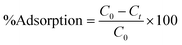 | (1) |
| |  | (2) |
where C0 (mg L−1) and Ct (mg L−1) are the initial dye concentration and final concentration after time, t min, and m is the mass of adsorbent in g L−1. To optimize the optimal adsorption condition, the batch adsorption experiment was carried out by altering the test parameters such as adsorbent dose, initial dye concentration, contact time, temperature, and pH.
2.4. Statistical procedure
All the malachite green dye adsorption batch tests were done in triplicate. Microsoft Excel 2019 was used to calculate the kinetic and isotherm study results. The graphs were then drawn using some of the non-linear forms of kinetic and isotherm models in OriginPro 2022b. Error bar graphs and regression correlation coefficients (R2) were used to demonstrate the relevance of data trends and the goodness of fit.
3. Results and discussion
A simple co-precipitation method was adopted to synthesize CeO2 NPs in the absence of any additive. The purified dried samples were characterized by different spectroscopic, microscopic, and diffractometric techniques, as discussed in detail in the ESI.†
3.1. X-ray diffraction study
The X-ray diffraction (XRD) patterns of the samples CeO-1 and CeO-2 are shown in Fig. 1. The XRD pattern of both the samples CeO-1 prepared using 0.5 M NaOH and CeO-2 prepared using 1.0 M NaOH display distinct diffraction peaks at 2θ = 28.5, 33.0, 47.4, 56.1, 69.2, 76.7, 78.9 and 88.1 which are assigned to the (111), (200), (220), (311), (400), (331), (420) and (422) lattice planes of the fluorite-type face-centred cubic (fcc) structure of CeO2 (JCPDF Card No. 32-0394; space group Fm![[3 with combining macron]](https://www.rsc.org/images/entities/char_0033_0304.gif) m).51 The broad nature of the diffraction peaks is indicative of smaller-sized particles while the absence of peaks belonging to other impurities confirmed the high purity of the as-prepared CeO2. The average crystallite size of the particles in samples CeO-1 and CeO-2 as calculated using Scherrer's formula (eqn (3)) using intense peaks due to (111), (220) and (311) planes is 3.4 and 3.7 nm, respectively.
m).51 The broad nature of the diffraction peaks is indicative of smaller-sized particles while the absence of peaks belonging to other impurities confirmed the high purity of the as-prepared CeO2. The average crystallite size of the particles in samples CeO-1 and CeO-2 as calculated using Scherrer's formula (eqn (3)) using intense peaks due to (111), (220) and (311) planes is 3.4 and 3.7 nm, respectively.| |  | (3) |
where λ represents the wavelength of the X-ray radiation (0.154 nm), θ represents the angle of diffraction and β represents the full width at half maximum (FWHM). The calculated average value of the lattice constant from the XRD pattern was found to be 0.54 nm which matches well with the value for CeO2 NPs reported earlier.66
 |
| | Fig. 1 XRD patterns of different samples of CeO2 NPs. | |
3.2. Microscopic study
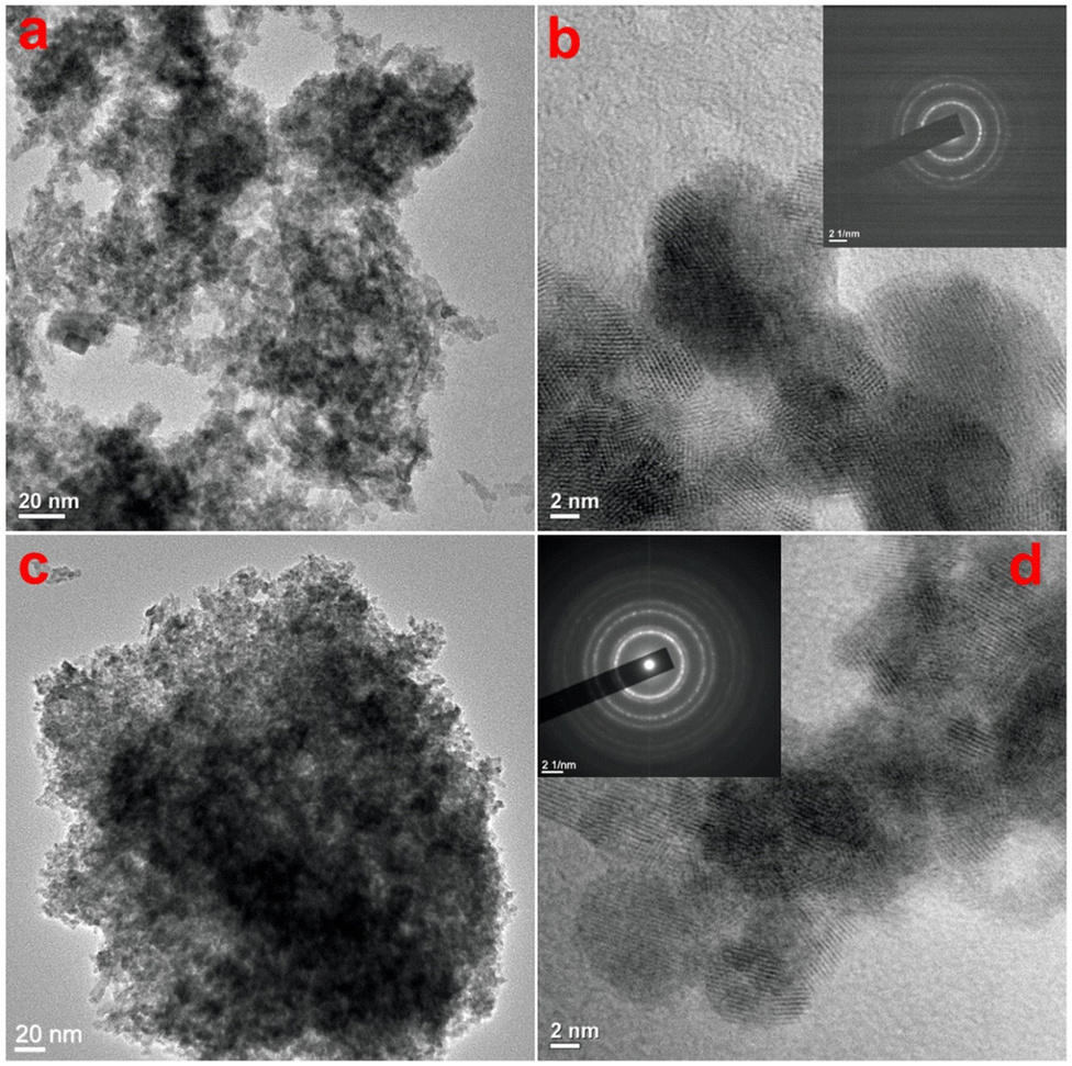
To check the topography of the formed CeO2, microscopic analysis of the products was carried out. The scanning electron microscopic (SEM) images of both samples are shown in Fig. S1 (ESI†), which shows the formation of smaller-sized particles in both samples. As the SEM images are unable to give an idea about the sizes and morphology of the particles, transmission electron microscopy (TEM) studies were undertaken on both samples to study in detail the morphological evolution. Fig. 2a shows the TEM image of sample CeO-1 prepared with 0.5 M NaOH, which shows the presence of aggregated particles of CeO2. A high-resolution TEM image shown in Fig. 2b shows that these particles are nearly spherical with sizes less than 10 nm. Furthermore, the presence of well-resolved lattice fringes confirmed the formation of crystalline CeO2 NPs. The interplane distance as measured using ImageJ software (NIH, USA) was found to be 0.33 nm which corresponds to the (111) lattice plane in CeO2. The corresponding selected area electron diffraction (SAED) pattern (inset in Fig. 2b) shows the presence of a ring pattern confirming the polycrystalline nature of the samples. This observation might also be because the particles are mostly overlapped with each other which is responsible for the ring pattern. The TEM image of sample CeO-2 prepared with 1.0 M NaOH is shown in Fig. 2c which again shows the presence of aggregated particles of CeO2. The high-resolution TEM image shown in Fig. 2d shows that these particles are also spherical with sizes less than 10 nm. But in this case, the particles are more uniform compared to those in sample CeO-1. This might be due to the faster nucleation rate at higher NaOH concentrations where many nuclei are formed at once and undergo secondary nucleation to give more uniform particles. Furthermore, the presence of well-resolved lattice fringes in the high-resolution TEM image again confirmed the formation of well-crystalline CeO2 NPs. The interplane distance was found to be 0.31 nm which corresponds to the (111) lattice plane in CeO2. The corresponding selected area electron diffraction (SAED) pattern (inset in Fig. 2d) shows the presence of a ring pattern as observed in the case of sample CeO-1. The energy dispersive X-ray spectroscopy (EDX) study on sample CeO-2 confirmed the presence of Ce (35.6%) and O (64.4%) in the sample (Fig. S2, ESI†). The additional peaks observed in the spectrum are assigned to C and Cu which corresponds to the carbon and copper present in the TEM grid used to hold the sample.
 |
| | Fig. 2 TEM images of samples (a and b) CeO-1 and (c and d) CeO-2. The insets in (b) and (d) correspond to the SAED patterns of the respective samples. | |
3.3. Study of the surface properties
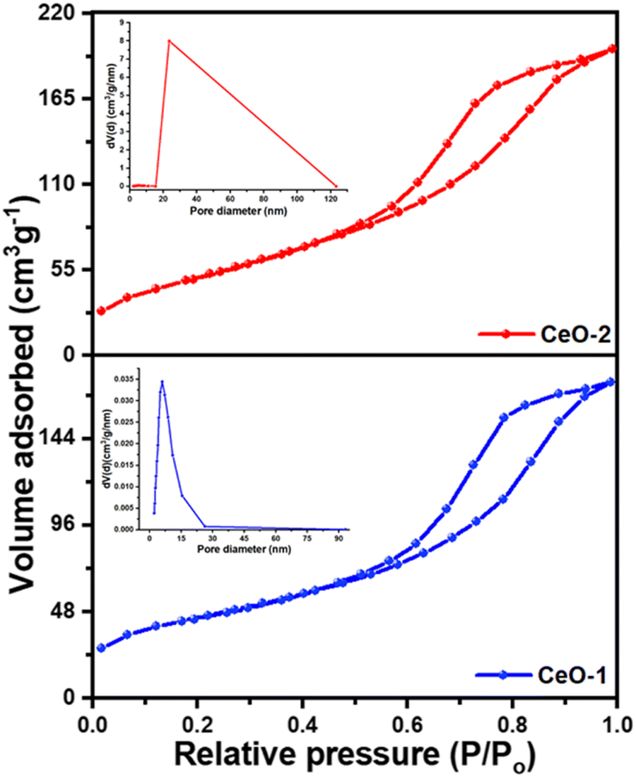
To get an insight of the surface characteristics, a N2 gas adsorption–desorption study was carried out on both samples (Fig. 3). Both the samples CeO-1 and CeO-2 exhibit isotherms which seem to be a combination of type II and type V isotherms with type H3 hysteresis loops. These types of loops are exhibited by the aggregates of plate-like mesoporous particles that give rise to slit-shaped pores and does not show any limiting adsorption at high P/P0.67 The multi-point Brunauer–Emmett Teller (BET) surface area analysis showed that the surface area values are 159.6 m2 g−1 and 189.3 m2 g−1, respectively, for samples CeO-1 and CeO-2. Additionally, the pore diameters and volumes of the samples were determined from the adsorption–desorption isotherms following the well-known Barrett–Joyner–Halenda (BJH) method (insets in Fig. 3). The pore volume of sample CeO-2 is 0.316 cm3 g−1 which is higher than that of sample CeO-1 (0.268 cm3 g−1). The average pore diameters in the samples are 5.983 and 5.165 nm, respectively, for samples CeO-1 and CeO-2. The results indicated the presence of mesopores in both samples.
 |
| | Fig. 3 N2 gas adsorption–desorption isotherms of different samples of CeO2 NPs. Insets in the figure represent the BJH plots of the pore size distribution of the respective samples. | |
3.4. Study of the optical properties
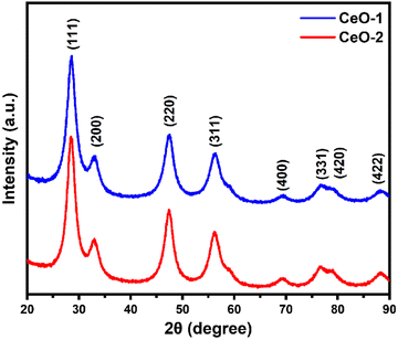
Fig. 4a illustrates the UV-vis absorption spectra of samples CeO-1 and CeO-2 dispersed in double distilled water. The UV-vis absorption spectrum of sample CeO-1 displays absorption bands at 335 nm while sample CeO-2 exhibited absorption bands at 315 nm. The difference in the absorption band in different samples might be attributed to the different sizes of the particles in different samples. Such absorption below 400 nm is associated with the charge transfer transitions from the 2p valence band (VB) of O2− to the 4f conduction band (CB) of Ce4+, which overruns the well-known f–f spin–orbit splitting of the Ce 4f state.68 Because of the significant light absorption caused by the charge transfer between O2− and Ce4+, CeO2 shows photoluminescence (PL). Fig. 4b displays the room temperature PL spectra of both the samples of CeO2 NPs measured at an excitation wavelength of 320 nm. The PL spectra of both samples exhibited nearly identical emission peaks, with a strong peak at 420 nm and three relatively weak peaks at 486, 530, and 601 nm. Similar emission peaks were reported earlier for CeO2 NPs synthesized by the conventional sol–gel method.66 Surface defects and relative oxygen vacancies in CeO2 are believed to be responsible for the strong emission band at 420 nm and the weak emission band at 486 nm.66 The presence of a yellow emission band at 530 nm could be due to interstitial oxygen defects as reported earlier.66 The transfer of charge carriers between Ce's 4f conduction bands and O's 2p valence band in CeO2 explains the relative oxygen vacancies.66
 |
| | Fig. 4 (a) UV-vis absorption spectra and (b) room temperature PL spectra of different samples of CeO2 NPs. The PL spectra were recorded at an excitation wavelength of 320 nm. | |
3.5. Malachite green dye adsorption study
3.5.1. Effect of contact time.
To examine the adsorption performance of the as-prepared samples, i.e., samples CeO-1 and CeO-2, a preliminary test of malachite green dye adsorption was performed in batch mode for 150 min with an initial malachite green dye concentration of 50 mg L−1 and an adsorbent dose of 0.6 g L−1. In 120 min, sample CeO-2 displayed about 98.0% malachite green dye adsorption, whereas sample CeO-1 could remove only 81.7% of dye in the same time scale (Fig. 5). After 120 min, the %adsorption of dye in sample CeO-2 is practically constant, whereas it increases progressively from 81.7% to 86.1% in 150 min with sample CeO-1. The existence of many unoccupied adsorbent sites on the adsorbent, as well as a significant malachite green dye concentration gradient between the solution and the adsorbent surface, accounts for the strong adsorptive removal rate. As the adsorption sites are occupied over time, the rate of malachite green dye adsorption decreases resulting in the flattening of the curves and thereby ultimately an equilibrium is reached. Fig. 5 further shows that, under the tested conditions, sample CeO-2 performed as a better adsorbent for malachite green dye compared to the sample CeO-1. As discussed in Section 3.3, the greater effective surface area of sample CeO-2 might account for the improved adsorption performance. So, we chose sample CeO-2 as the adsorbent for future investigation and optimization of the method in terms of adsorbent dose, initial malachite green dye concentration, and pH.
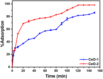 |
| | Fig. 5 Variation of %adsorption of malachite green dye with time on different samples of CeO2 NPs. Conditions: initial malachite green dye concentration (50 mg L−1); adsorbent dose (0.6 g L−1); time (150 min); temperature (303 K); pH (∼7). | |
3.5.2. Effect of adsorbent loading.
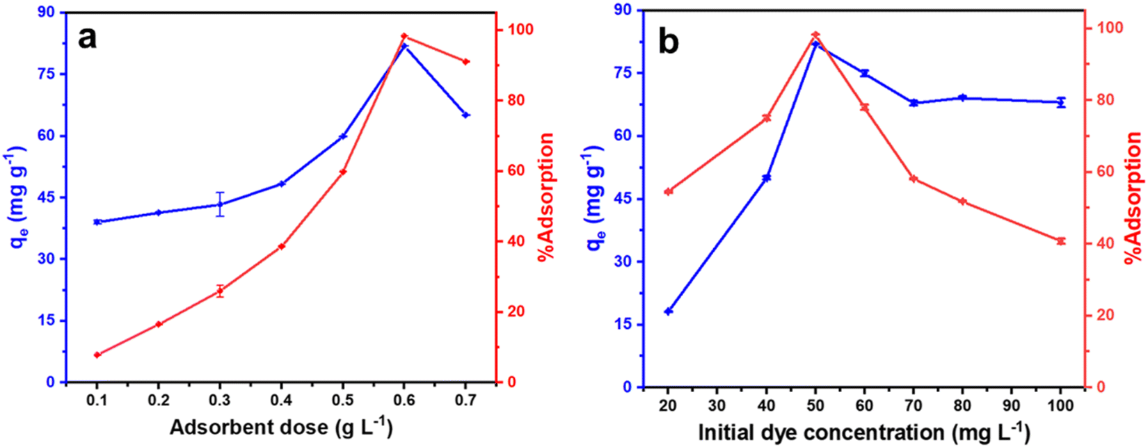
To find the optimum amount of the adsorbent for efficient dye removal, the amount of adsorbent (sample CeO-2) was varied from 0.1 to 0.7 g L−1 with a fixed initial malachite green dye concentration of 50 mg L−1. When the adsorbent loading was increased from 0.1 to 0.5 g L−1, a gradual increase in the %adsorption of malachite green dye was observed from 12.7 to 61.4% and then it increased sharply to 98.3% as the adsorbent loading was increased to 0.6 g L−1 (Fig. 6a). Furthermore, an increase in the adsorbent dose to 0.7 g L−1 resulted in a decrease in the %adsorption of malachite green dye. Simultaneously, the adsorption capacity, qe, of CeO2 NPs increased steadily from 39.0 to 59.8 mg g−1 as the adsorbent dose was increased from 0.1 to 0.5 g L−1, then it increased sharply to 81.9 mg g−1 as the adsorbent dose was increased to 0.6 g L−1. Further increase in the adsorbent dose to 0.7 g L−1 again resulted in the decrease of the adsorption capacity, qe, of CeO2 NPs to 65.1 mg g−1. With a fixed dye concentration, when the adsorbent dose was increased, due to the presence of an increased number of surface-active sites on the adsorbent, the %adsorption of dye as well as the adsorption capacity, qe increased gradually and ultimately reached a maximum at an adsorbent dose of 0.6 g L−1. A similar observation was reported earlier by Eltaweil and his group.2 However, a further increase in the adsorbent dose might result in the partial agglomeration of the adsorbent resulting in a less accessible surface site for the dye adsorption causing a decrease in the %adsorption of the dye. Similarly, the adsorption capacity, qe which is expressed in mg of dye adsorbed per g of the adsorbent, also decreased significantly as the adsorbent dose was increased due to the limited surface-active sites which are not enough for the added dye. Accordingly, the adsorbent dose was set at 0.6 g L−1 for further investigation in detail.
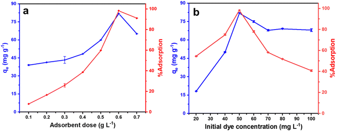 |
| | Fig. 6 Effect of (a) adsorbent dose at a fixed dye concentration of 50 mg L−1 and (b) initial dye concentration at a fixed adsorbent dose of 0.6 g L−1 on the adsorption performance of CeO2 NPs (sample CeO-2). Condition: temperature (303 K); pH (∼7). | |
3.5.3. Effect of initial malachite green dye concentration.
The influence of malachite green dye concentration on adsorption performance was examined using an adsorbent dosage of 0.6 g L−1 at 303 K with the initial dye concentration range of 20 to 100 mg L−1. With an increase in initial malachite green dye concentration from 20 to 50 mg L−1, both the %adsorption of malachite green dye and adsorption capacity, qe of CeO2 NPs increased rapidly (Fig. 6b). However, as the initial malachite green dye concentration was increased further from 50 to 100 mg L−1, a sharp decrease in the %adsorption of malachite green dye was observed. This happens because, at lower dye concentrations, the available surface sites on the adsorbent remain free so more dye molecules undergo adsorption as the dye concentration was increased. At a certain dye concentration, all the surface-active sites on the adsorbent are occupied and so become saturated. At this point the %adsorption of dye, as well as the adsorption capacity of CeO2 NPs, became maximum. Further increase in the dye concentration resulted in the decrease of both the %adsorption of dye as well as the adsorption capacity. This is due to the presence of inadequate surface sites on the adsorbent and so many dye molecules remained free in the solution causing an overall decrease in the adsorption performance. This observation persuaded us to set the initial malachite green dye concentration at 50 mg L−1 for further investigation.
3.5.4. Effect of pH.
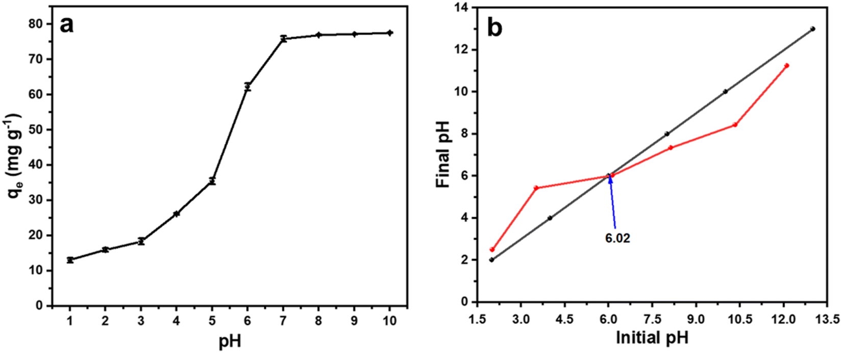
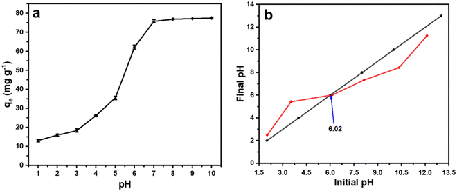
It is well known that the pH of the medium has a significant impact on the adsorption of malachite green dye.26 To study the effect of pH on the malachite green dye adsorption in the current study, we varied the pH of the medium from 1.0 to 10.0 by using 0.1 M HCl or 0.1 M NaOH solution and performed the adsorption study with 0.6 g L−1 of sample CeO-2 and 50 mg L−1 malachite green dye solution. Fig. 7a depicts the influence of pH on the adsorption performance of CeO2 NPs for malachite green dye. The curve shows that the adsorption capacity, qe, of CeO2 NPs increased steadily when the pH was raised from 1.0 to 7.0, reached almost equilibrium at pH (∼7), and then nearly flattened after pH 7.0. To understand the adsorption mechanism, the pHzpc (pH at a zero-point charge) value of the adsorbent was evaluated using the pH drift method (Fig. 7b).69 The value of pHzpc was found to be 6.02, which means that at a pH above 6.02, the surface of the adsorbent becomes more negatively charged due to an increased number of OH− ions on the adsorbent surface, and hence electrostatic interaction between the cationic dye, i.e., malachite green, and the negative adsorbent surface results in increased malachite green dye adsorption. At a pH below pHzpc, the surface of the adsorbent is positively charged, which induces coulombic repulsion to the incoming cationic dye, and thus the adsorption performance was decreased significantly.
 |
| | Fig. 7 (a) The effect of pH on the adsorption performance of CeO2 NPs (sample CeO-2) and (b) plot of final pH versus initial pH obtained using the pH drift method. | |
Moreover, at lower pH, a greater number of H3O+ are present in the medium, which also competes with malachite green dye for adsorption, which might also be responsible for the low performance of CeO2 NPs at lower pH ranges.
3.5.5. Adsorption kinetics.
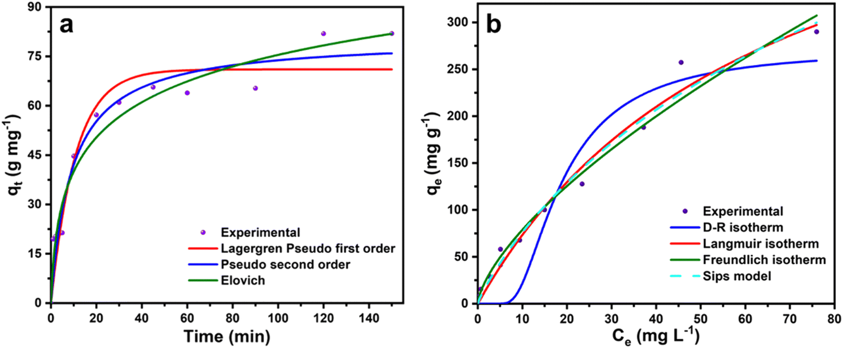
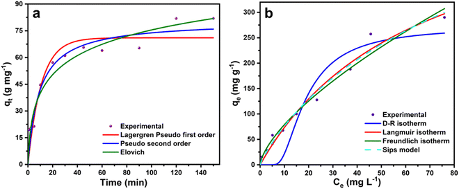
The kinetic study on the malachite green dye adsorption by CeO2 NPs was performed with 50 mg L−1 malachite green dye solution on sample CeO-2 with an adsorbent dose of 0.6 g L−1 at 303 K and the variation of qt with time, t is shown in Fig. 8a. The kinetic data were fitted based on different kinetic models (Table S1, ESI†) and the obtained kinetic parameters are presented in Table 1. The comparison of the correlation coefficient (R2) values (Table 1) suggests that both the Lagergren pseudo-first-order and pseudo-second-order models could be equally favourable to describe the experimental data. However, the comparison of the experimental and theoretical values of qe indicates that the pseudo-second-order gives much less deviation (1.71%), compared to that of the Lagergren pseudo-first-order (15.39%). However, among these two models, the pseudo-second-order model (best R2 values in Table 1) was the best to describe the adsorptive kinetics, which indicated the involvement of chemisorption in the adsorption of malachite green dye onto CeO2 NPs. The high correlation coefficient (R2) value (0.9602) obtained from the Elovich plot also supports the idea that the adsorption might be primarily activated via chemisorption. The initial adsorption constant (α) is very high compared to the desorption constant (β) suggesting favourable adsorbent–adsorbate interaction.
 |
| | Fig. 8 Non-linear fitted curves of malachite green dye adsorption on sample CeO-2 based on different (a) kinetic models and (b) isotherm models. | |
Table 1 Kinetic rate coefficients for adsorption of malachite green dye with different adsorbents (k1 in min−1 and k2 in g mg−1 min−1, qe in mg g−1, α in g mg−1 min−1, β in mg g−1 min−1), qe(Th) = qe(theoretical); %D = (% deviation)
| Model |
Parameters |
Sample CeO-2 |
| Lagergren pseudo-first-order |
k
1
|
0.09 |
|
R
2
|
0.9294 |
|
q
e(Th) |
71.04 |
| % D |
15.39 |
| Pseudo-second-order |
k
2
|
0.0014 |
|
R
2
|
0.9545 |
|
q
e(Th) |
80.59 |
| % D |
1.71 |
| Elovich |
α
|
18.03 |
|
β
|
0.06 |
|
R
2
|
0.9602 |
3.5.6. Adsorption isotherm.
To determine the adsorption capacity of the particular adsorbent, namely, sample CeO-2, the isotherm experiment was carried out on a thermostatic orbital shaker (REMI CIS-18 PLUS, India) at temperatures 293, 303, and 313 K with different initial malachite green dye concentrations varying from 5 to 250 mg L−1. Furthermore, to calculate the different adsorption parameters, we fitted the adsorption equilibrium data to some of the non-linear isotherm models (Fig. 8b) such as Freundlich, Langmuir, Dubinin–Radushkevich (D–R), and Sips isotherm (Table S2, ESI†). The different estimated adsorption parameters are presented in Table 2. The correlation coefficient (R2) values at 293, 303, and 313 K showed a better fit of the experimental data to the Freundlich, Langmuir, and Sips isotherm models. While the experimental data are not well-fitted to the D–R isotherm model. The Freundlich adsorption capacity KF increases from 15.67 to 20.37 on increasing the temperature, indicating that the adsorption is favoured at a higher temperature according to the Freundlich isotherm. Also, the values of n are higher than 1.0 and increase with an increase in temperature indicating favourable adsorption at higher temperatures. Meanwhile, the Langmuir monolayer adsorption capacity, qm increases from 521.22 to 558.68 mg g−1 on increasing the temperature from 293 to 313 K indicating that at higher temperatures, the Langmuir monolayer formation is also more favoured. According to the Sips model, the maximum adsorption capacity is 740.54 mg g−1 at 303 K. The high mean sorption energy, E obtained from the D–R isotherm implied the formation of a chemical bond between the adsorbent and malachite green dye.
Table 2 Isotherm data for adsorption of malachite green dye onto the adsorbents (sample CeO-2) at different temperatures. (KF in mg1−1/n L1/n g−1, qm in mg g−1, b in L mg−1, qs in mg g−1, kad in mol2 k−1 J−2, E in kJ mol−1)
| Isotherm model |
Isotherm parameters |
293 K |
303 K |
313 K |
| Freundlich |
K
F
|
15.67 |
16.81 |
20.37 |
|
n
|
1.50 |
1.49 |
1.52 |
|
R
2
|
0.9719 |
0.9792 |
0.9821 |
| Langmuir |
q
m
|
521.22 |
552.77 |
558.68 |
|
b
|
0.014 |
0.015 |
0.019 |
|
R
2
|
0.9795 |
0.9814 |
0.9870 |
| D–R |
q
s
|
268.47 |
271.71 |
296.88 |
|
k
ad × 105 |
5.88 |
4.37 |
3.47 |
|
R
2
|
0.8837 |
0.8753 |
0.9002 |
|
E
|
92.21 |
106.97 |
120.04 |
| Sips |
q
ms
|
522.02 |
740.54 |
635.96 |
|
k
s
|
0.01483 |
0.01518 |
0.01927 |
|
m
s
|
0.9991 |
0.87831 |
0.93202 |
|
R
2
|
0.9795 |
0.98225 |
0.9872 |
3.5.8. Reusability test of the adsorbent.
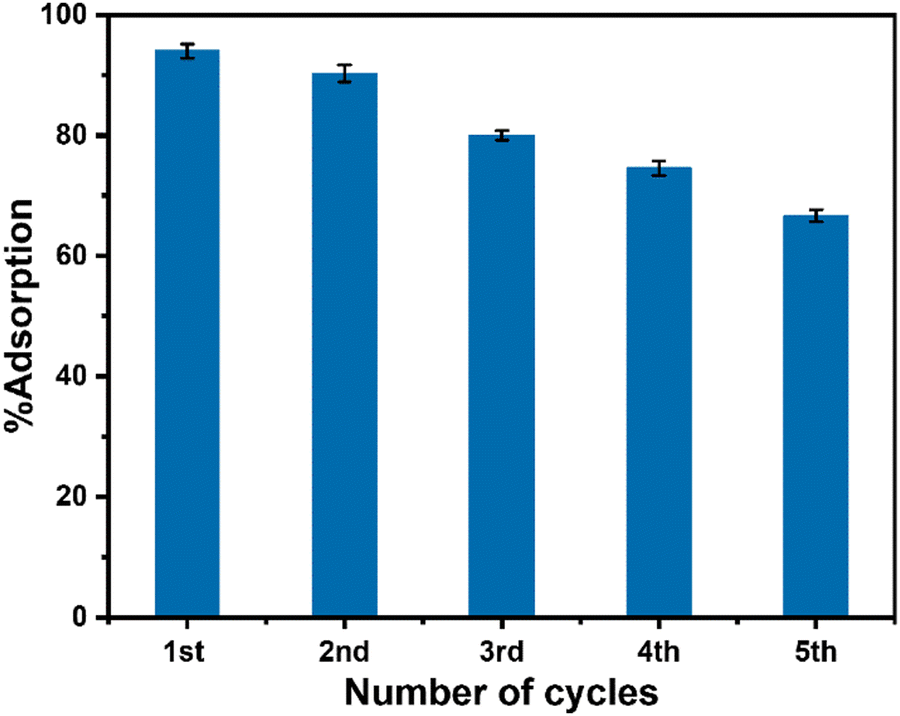
To check the reusability of CeO2 NPs (sample CeO-2), a batch adsorption study was performed under the optimized conditions with five-fold adsorbent and adsorbate amount and the adsorbent was isolated after the adsorption experiment by centrifugation. The isolated adsorbent was purified by washing with ethanol:distilled water (1:1) solution followed by washing with distilled water. The washing process was repeated five times and finally, the isolated used adsorbent was dried for a further adsorption experiment with another set of fresh dye solutions maintaining all other conditions identical to the parenting experiment. This process of isolation of the adsorbent and reuse of the isolated adsorbent in the dye removal experiment was repeated for five cycles. The performance of the used adsorbent is presented in Fig. 9 which indicated that the adsorption performance of CeO2 NPs decreased gradually after the first cycle of adsorption. The reason for this decrease might be due to the leaching out of the adsorbent during its recovery as well as the blocking of some active sites of the adsorbent by malachite green dye. Furthermore, to check the stability of the used adsorbent, XRD and TEM study was carried out on the recovered sample. The XRD pattern of reused CeO2 NPs (Fig. 10a) is the same as the XRD pattern of the parent sample which confirmed that there is no change in the structure and crystalline properties of the adsorbent due to malachite green dye adsorption. Also, the TEM results (Fig. 10b) showed no morphological change in the CeO2 NPs due to malachite green dye adsorption. Even the crystalline properties (Fig. 10d) and interplanar distance values (Fig. 10c) remained intact after dye adsorption as observed from the SAED and HRTEM study. These results confirmed that the adsorbent is highly stable under the condition of the experiment, which increases the versatility of the adsorbent for use for different purposes.
 |
| | Fig. 9 Performance of the used CeO2 NPs in malachite green dye removal. | |
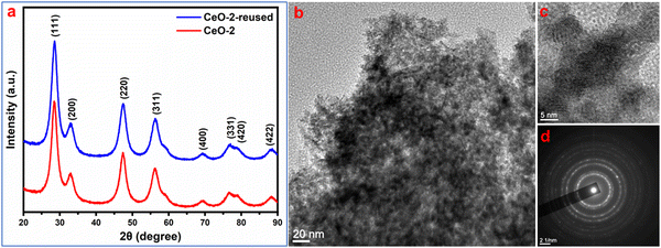 |
| | Fig. 10 (a) XRD pattern and (b) TEM image of recovered CeO2 NPs. (c) HRTEM image and (d) SAED pattern of the respective sample. | |
3.5.9. Comparison of the adsorption performance of CeO2 NPs with other reported adsorbents.
The adsorption performance of CeO2 NPs has been compared with other similar reported adsorbents (Table 4) as well as the commercial CeO2. The table shows that CeO2 NPs possess a high surface area of 189.3 m2 g−1 and exhibit a high Langmuir monolayer adsorption capacity, qm, of 552.77 mg g−1 at temperature 303 K. In comparison to other allied adsorbents, the performance of CeO2 NPs is excellent. This suggests that CeO2 NPs can be used as an excellent and effective adsorbent for the removal of malachite green dye from aqueous media.
Table 4 Comparison of the adsorption performance of CeO2 NPs with other reported adsorbents
| Adsorbent |
Surface area (m2 g−1) |
Dye concentration (mg L−1) |
pH |
Adsorbent dose (g L−1) |
Time (min) |
Adsorption capacity, qm (mg g−1) |
Ref. |
| ZIF-8@Fe/Ni |
195.160 |
50 |
4.5 |
0.5 |
120 |
151.520 |
23
|
| AC pellets |
979 |
25–800 |
3.2 |
— |
72 h |
395 |
24
|
| Magnetic cobalt oxide NPs |
8.351 |
40 |
7 |
— |
120 |
238.10 |
30
|
| Sodium alginate coated Fe3O4 NP |
— |
10 |
7.0 |
0.6 |
20 |
47.84 |
28
|
| AC supported SnO2 NPs |
— |
15 |
5 |
— |
30 |
142.87 |
32
|
| MgFe2O4 NPs |
70.266 |
50 |
8.0 |
0.5 |
15 |
487.60 |
71
|
| AC supported Mn-doped CuO NPs |
— |
30 |
10 |
0.4 |
4.5 |
320.5 |
65
|
| NiO nanoparticles |
11.617 |
50 |
7.0 |
4.0 |
120 |
87.72 |
29
|
| AC supported ZnO NP |
— |
25–300 |
7.0 |
1.0 |
5–120 |
303.0 |
22
|
| Commercial CeO2 (bulk) |
— |
50 |
7.0 |
0.6 |
120 |
65.2 |
This work |
| CeO2 NPs |
189.3 |
50 |
7.0 |
0.6 |
120 |
552.77 |
This work |
4. Conclusion
In the current report, we aim at the synthesis of CeO2 NPs in the absence of any additive for use as a cost-effective and efficient adsorbent for malachite green dye removal from water. The CeO2 NPs have been successfully synthesized by the co-precipitation method under mild conditions. The formed CeO2 NPs are spherical and crystalline possessing surface areas in the range of 159.6 to 189.3 m2 g−1. The as-synthesized CeO2 NPs have been successfully used for the adsorptive removal of malachite green dye from water. The adsorption performance of CeO2 NPs towards malachite green is affected by the adsorbent loadings, contact times, initial dye concentrations and pH. The adsorption isotherm data are well fitted to the Langmuir model and the Sips model with Langmuir monolayer adsorption capacity, qm, of 558.68 mg g−1 at 313 K and Sips adsorption capacity, qms of 740.5 mg g−1 at 303 K. The adsorption process is endothermic and thermodynamically favourable following pseudo-second-order kinetics. Typically, malachite green dye adsorption on CeO2 NPs occurs via electrostatic interaction and so is chemical. The adsorbent is stable and can be reused for up to five cycles with little loss in the adsorption performance.
Author contributions
All authors contributed to the study's conception and design. XB carried out the experiments, formal analysis, investigation, and writing of the original draft. ED carried out the experiments, (materials synthesis). MHR supervised the research, provided conceptualization, and did the editing. All authors read and approved the final manuscript.
Conflicts of interest
The authors have no relevant financial or non-financial interests to declare.
Acknowledgements
The research was supported by Science and Engineering Research Board (SERB), India (Grant No. CRG/2019/002026). The authors thank CNN-JMI, Delhi, NEIST Jorhat, MARC Bangalore and SAIF GU for use of the instrumental facilities.
References
-
J. Ahmed, A. Thakur and A. Goyal, Biological Treatment of Industrial Wastewater, The Royal Society of Chemistry, 2022, ch. 1, pp. 1–14 10.1039/9781839165399-00001.
- I. K. Basha, E. M. Abd El-Monaem, R. E. Khalifa, A. M. Omer and A. S. Eltaweil, Sci. Rep., 2022, 12, 9339 CrossRef CAS PubMed.
- A. S. Eltaweil, H. Ali Mohamed, E. M. Abd El-Monaem and G. M. El-Subruiti, Adv. Powder Technol., 2020, 31, 1253–1263 CrossRef CAS.
- In Handbook of Textile and Industrial Dyeing, ed. M. Clark, Woodhead Publishing, 2011 Search PubMed.
- S. Srivastava, R. Sinha and D. Roy, Aquat. Toxicol., 2004, 66, 319–329 CrossRef CAS PubMed.
-
Q. Nie and S. Nie, Evaluation Technologies for Food Quality, Elsevier, 2019, pp. 267–299 Search PubMed.
- J. Kanhere, R. Gopinathan and J. Banerjee, Water, Air, Soil Pollut., 2014, 225, 2134 CrossRef.
- S. J. Culp and F. A. Beland, J. Am. Coll. Toxicol., 1996, 15, 219–238 CrossRef.
- D. C. Roy, S. K. Biswas, M. M. Sheam, M. R. Hasan, A. K. Saha, A. K. Roy, M. E. Haque, M. M. Rahman and S.-S. Tang, Curr. Res. Microb. Sci., 2020, 1, 37–43 Search PubMed.
- X. Zhou, J. Zhang, Z. Pan and D. Li, Crit. Rev. Anal. Chem., 2019, 49, 1–20 CrossRef CAS PubMed.
- T. Arunprasath, S. Sudalai, R. Meenatchi, K. Jeyavishnu and A. Arumugam, Biocatal. Agric. Biotechnol., 2019, 17, 672–679 CrossRef.
- B. H. Hameed and T. W. Lee, J. Hazard. Mater., 2009, 164, 468–472 CrossRef CAS PubMed.
- Y.-C. Lee, E. J. Kim, J.-W. Yang and H.-J. Shin, J. Hazard. Mater., 2011, 192, 62–70 CAS.
- N. P. Raval, P. U. Shah and N. K. Shah, Appl. Water Sci., 2017, 7, 3407–3445 CrossRef CAS.
- Y. Yin, C. Li, C. Song, P. Tao, M. Sun, Z. Pan, T. Wang and M. Shao, Colloids Surf., A, 2016, 506, 629–636 CrossRef CAS.
- W.-T. Tsai and H.-R. Chen, J. Hazard. Mater., 2010, 175, 844–849 CrossRef CAS PubMed.
- G. Sarojini, S. Venkatesh Babu, N. Rajamohan and M. Rajasimman, Environ. Res., 2022, 204, 112132 CrossRef CAS PubMed.
- K. Tewari, G. Singhal and R. K. Arya, Rev. Chem. Eng., 2018, 34, 427–453 CrossRef CAS.
- M. T. Yagub, T. K. Sen, S. Afroze and H. M. Ang, Adv. Colloid Interface Sci., 2014, 209, 172–184 CrossRef CAS PubMed.
- X. Borgohain and H. Rashid, Environ. Sci. Pollut. Res., 2022, 29, 70056–70069 CrossRef CAS PubMed.
- G. K. Sarma, A. Khan, A. M. El-Toni and M. H. Rashid, J. Hazard. Mater., 2019, 380, 120838 CrossRef CAS PubMed.
- E. Altıntıg, M. Yenigun, A. Sarı, H. Altundag, M. Tuzen and T. A. Saleh, Environ. Technol. Innov., 2021, 21, 101305 CrossRef.
- T. Zhang, X. Jin, G. Owens and Z. Chen, J. Colloid Interface Sci., 2021, 594, 398–408 CrossRef CAS PubMed.
- S. H. Tang and M. A. Ahmad Zaini, J. Cleaner Prod., 2020, 253, 119970 CrossRef CAS.
- E. Altintig, M. Onaran, A. Sarı, H. Altundag and M. Tuzen, Mater. Chem. Phys., 2018, 220, 313–321 CrossRef CAS.
- M. Naushad, A. A. Alqadami, Z. A. AlOthman, I. H. Alsohaimi, M. S. Algamdi and A. M. Aldawsari, J. Mol. Liq., 2019, 293, 111442 CrossRef CAS.
- F. Zaoui, F. Zohra Choumane and A. Hakem, Mater. Today: Proc., 2022, 49, 1105–1111 CAS.
- A. Mohammadi, H. Daemi and M. Barikani, Int. J. Biol. Macromol., 2014, 69, 447–455 CrossRef CAS PubMed.
- J. Mohanta, B. Dey and S. Dey, ACS Omega, 2020, 5, 16510–16520 CrossRef CAS PubMed.
- J. Mohanta, B. Dey and S. Dey, J. Chem. Eng. Data, 2020, 65, 2819–2829 CrossRef CAS.
- M. Rajabi, K. Mahanpoor and O. Moradi, Composites, Part B, 2019, 167, 544–555 CrossRef CAS.
- A. Shamsizadeh, M. Ghaedi, A. Ansari, S. Azizian and M. Purkait, J. Mol. Liq., 2014, 195, 212–218 CrossRef CAS.
- D. Wang, L. Liu, X. Jiang, J. Yu and X. Chen, Colloids Surf., A, 2015, 466, 166–173 CrossRef CAS.
- K. Y. Kumar, H. Muralidhara, Y. A. Nayaka, J. Balasubramanyam and H. Hanumanthappa, Powder Technol., 2013, 246, 125–136 CrossRef CAS.
- M. Nagpal and R. Kakkar, Sep. Purif. Technol., 2019, 211, 522–539 CrossRef CAS.
-
S. C. Gad, in Encyclopedia of Toxicology, ed. P. Wexler, Elsevier, New York, 2nd edn, 2005, pp. 502–503 DOI:10.1016/B0-12-369400-0/00200-3.
-
A. Younis, D. Chu and S. Li, in Functionalized Nanomaterials, ed. M. A. Farrukh, IntechOpen, 2016, ch. 3 DOI:10.5772/65937.
- B. Park, K. Donaldson, R. Duffin, L. Tran, F. Kelly, I. Mudway, J.-P. Morin, R. Guest, P. Jenkinson and Z. Samaras, Inhal. Toxicol., 2008, 20, 547–566 CrossRef CAS PubMed.
- L. G. Ecco, M. Fedel, A. Ahniyaz and F. Deflorian, Prog. Org. Coat., 2014, 77, 2031–2038 CrossRef CAS.
- P. Janoš, J. Ederer, V. Pilařová, J. Henych, J. Tolasz, D. Milde and T. Opletal, Wear, 2016, 362–363, 114–120 CrossRef.
- K. Reed, A. Cormack, A. Kulkarni, M. Mayton, D. Sayle, F. Klaessig and B. Stadler, Environ. Sci.: Nano, 2014, 1, 390–405 RSC.
- S. M. Hirst, A. Karakoti, S. Singh, W. Self, R. Tyler, S. Seal and C. M. Reilly, Environ. Toxicol., 2013, 28, 107–118 CrossRef CAS PubMed.
- I. Celardo, J. Z. Pedersen, E. Traversa and L. Ghibelli, Nanoscale, 2011, 3, 1411–1420 RSC.
- S. Sehar, I. Naz, A. Rehman, W. Sun, S. S. Alhewairini, M. N. Zahid and A. Younis, Appl. Organomet. Chem., 2021, 35, e6069 CrossRef CAS.
- N. M. Tomić, Z. D. Dohčević-Mitrović, N. M. Paunović, D. Ž. Mijin, N. D. Radić, B. V. Grbić, S. M. Aškrabić, B. M. Babić and D. V. Bajuk-Bogdanović, Langmuir, 2014, 30, 11582–11590 CrossRef PubMed.
- S. Chaudhary, P. Sharma, D. Singh, A. Umar and R. Kumar, ACS Sustainable Chem. Eng., 2017, 5, 6803–6816 CrossRef CAS.
- N.-C. Zheng, Z. Wang, J.-Y. Long, L.-J. Kong, D.-Y. Chen and Z.-Q. Liu, J. Colloid Interface Sci., 2018, 525, 225–233 CrossRef CAS PubMed.
- H. Xiao, Z. Ai and L. Zhang, J. Phys. Chem. C, 2009, 113, 16625–16630 CrossRef CAS.
- H. Imagawa, A. Suda, K. Yamamura and S. Sun, J. Phys. Chem. C, 2011, 115, 1740–1745 CrossRef CAS.
- D. N. Oosthuizen, D. E. Motaung and H. C. Swart, Appl. Surf. Sci., 2020, 505, 144356 CrossRef CAS.
- P. Li, B. Wang, C. Qin, C. Han, L. Sun and Y. Wang, Ceram. Int., 2020, 46, 19232–19240 CrossRef CAS.
- M. Lykaki, E. Pachatouridou, S. A. Carabineiro, E. Iliopoulou, C. Andriopoulou, N. Kallithrakas-Kontos, S. Boghosian and M. Konsolakis, Appl. Catal., B, 2018, 230, 18–28 CrossRef CAS.
- M. Lykaki, S. Stefa, S. A. C. Carabineiro, M. A. Soria, L. M. Madeira and M. Konsolakis, Catalysts, 2021, 11, 753 CrossRef CAS.
- N. Xu, J. Ye, Y. Tang, C. Man, G. He, H. Ye and G. Ning, Mater. Lett., 2012, 82, 199–201 CrossRef CAS.
- P. Jyothi, B. Anitha, S. Smitha, B. Vibitha, P. Krishna and N. J. Tharayil, Bull. Mater. Sci., 2020, 43, 1–7 CrossRef.
- H.-I. Chen and H.-Y. Chang, Ceram. Int., 2005, 31, 795–802 CrossRef CAS.
- P. L. Chen and I. W. Chen, J. Am. Chem. Soc., 1993, 76, 1577–1583 CAS.
- M. Lin, Z. Y. Fu, H. R. Tan, J. P. Y. Tan, S. C. Ng and E. Teo, Cryst. Growth Des., 2012, 12, 3296–3303 CrossRef CAS.
- T. C. Saikia, X. Borgohain, S. Iraqui and M. H. Rashid, ACS Omega, 2022, 7, 42126–42137 CrossRef PubMed.
- T. N. Ravishankar, T. Ramakrishnappa, G. Nagaraju and H. Rajanaika, ChemistryOpen, 2015, 4, 146–154 CrossRef CAS PubMed.
- N. A. M. Fadzil, M. H. Ab Rahim and G. P. Maniam, Mater. Res. Express, 2018, 5, 085019 CrossRef.
- K. R. B. Singh, V. Nayak, T. Sarkar and R. P. Singh, RSC Adv., 2020, 10, 27194–27214 RSC.
- W.-Q. Han, L. Wu and Y. Zhu, J. Am. Chem. Soc., 2005, 127, 12814–12815 CrossRef CAS PubMed.
- T. V. Tran, D. T. C. Nguyen, P. S. Kumar, A. T. M. Din, A. S. Qazaq and D.-V. N. Vo, Environ. Res., 2022, 214, 113925 CrossRef CAS PubMed.
- E. Sharifpour, E. Alipanahpour Dil, A. Asfaram, M. Ghaedi and A. Goudarzi, Appl. Organometal. Chem., 2019, 33, e4768 CrossRef.
- P. Tamizhdurai, S. Sakthinathan, S.-M. Chen, K. Shanthi, S. Sivasanker and P. Sangeetha, Sci. Rep., 2017, 7, 1–13 CrossRef PubMed.
- K. S. W. Sing, Pure Appl. Chem., 1985, 57, 603–619 CrossRef CAS.
- G. Jayakumar, A. Albert Irudayaraj and A. Dhayal Raj, Opt. Quantum Electron., 2019, 51, 312 CrossRef.
- G. Newcombe, R. Hayes and M. Drikas, Colloids Surf., A, 1993, 78, 65–71 CrossRef CAS.
- E. C. Lima, A. Hosseini-Bandegharaei, J. C. Moreno-Piraján and I. Anastopoulos, J. Mol. Liq., 2019, 273, 425–434 CrossRef CAS.
- P. Das, P. Debnath and A. Debnath, Environ. Nanotechnol. Monit. Manage., 2021, 16, 100506 CAS.
Footnotes |
| † Electronic supplementary information (ESI) available: Details of characterization techniques, Tables S1 and S2, and Fig. S1 and S2. See DOI: https://doi.org/10.1039/d2ma01019d |
| ‡ Current address: Life Science Division, Institute of Advanced Study in Science and Technology, Paschim Boragaon, Guwahati 781 035, Assam, India. |
|
| This journal is © The Royal Society of Chemistry 2023 |
Click here to see how this site uses Cookies. View our privacy policy here. 
 Open Access Article
 This Open Access Article is licensed under a Creative Commons Attribution-Non Commercial 3.0 Unported Licence
 ,
Emee
Das‡
and
Md. Harunar
Rashid
,
Emee
Das‡
and
Md. Harunar
Rashid