 Open Access Article
Seven-member-ring-based electron-transporting materials for high-efficiency OLEDs†
Kuo-Hsien
Chou‡
a,
Tun-Hao
Chen‡
a,
Xian-Qing
Huang
a,
Chia-Sheng
Huang
a,
Chih-Hao
Chang
b,
Chien-Tien
Chen
 *b and
Jwo-Huei
Jou
 *a
*a
aDepartment of Materials Science and Engineering, National Tsing Hua University, Hsinchu, Taiwan, Republic of China. E-mail: jjou@mx.nthu.edu.tw
bDepartment of Chemistry, National Tsing Hua University, Hsinchu, Taiwan, Republic of China. E-mail: ctchen@mx.nthu.edu.tw
First published on 28th January 2023
Abstract
Organic light-emitting diodes (OLEDs) have become the mainstream display technology and show potential in lighting. With a constant demand of higher efficiency and longer lifetime, the design and synthesis of better OLED materials are essential. Amongst these, electron-transporting materials (ETMs) consume about 30% of the applied energy. Developing ETMs with a high electron mobility and a high thermal stability is hence crucial. Seven-member-ring-based molecules are known to be highly thermally stable. They could be suitable for serving as ETMs if they also show good optoelectric characteristics. Herein, we have synthesized four seven-member-ring-based ETMs. A high efficiency was achieved for a green OLED by using 2′,12-di(pyridin-4-yl)spiro[dibenzo[3,4![[thin space (1/6-em)]](https://www.rsc.org/images/entities/char_2009.gif) :
:![[thin space (1/6-em)]](https://www.rsc.org/images/entities/char_2009.gif) 5,6]cyclohepta[1,2-b]pyridine-9,9′-fluorene] (DPP) as ETM. At 1000 cd m−2, for example, the power efficacy (PE) was increased from 23 to 32 lm W−1, an increase of 39%, when the typical 1,3,5-tris(N-phenylbenzimidazol-2-yl)benzene (TPBi) was replaced by DPP. The corresponding device lifetime at 5000 cd m−2 was increased from 1.4 to 2.0 h, an increase of 43%. The high efficiency may be attributed to the facts that DPP has an electron mobility (7.2 × 10⁻⁵ cm2 V−1 s−1) higher than that of TPBi (2.2 × 10⁻⁵ cm2 V−1 s−1) and has a highest occupied molecular orbital (HOMO) level (−6.3 eV) deeper than that of TPBi (−6.2 eV). Electrical simulation confirmed that the higher electron mobility could lead to a 5-fold increase in carrier recombination rate and the deeper HOMO level would lead to an increase of 15% in carrier recombination rate. The lifetime enhancement may be attributed to the high glass transition temperature of DPP (181 °C), being 124 °C for TPBi. However, DPP did not work for blue phosphorescent emitters, such as bis[2-(4,6-difluorophenyl)pyridinato-C2,N](picolinato)iridium (FIrpic), because its triplet energy (2.54 eV) is lower than that of FIrpic (2.65 eV). However, a high-efficiency blue OLED was achieved by using 4-(spiro[dibenzo[3,4
5,6]cyclohepta[1,2-b]pyridine-9,9′-fluorene] (DPP) as ETM. At 1000 cd m−2, for example, the power efficacy (PE) was increased from 23 to 32 lm W−1, an increase of 39%, when the typical 1,3,5-tris(N-phenylbenzimidazol-2-yl)benzene (TPBi) was replaced by DPP. The corresponding device lifetime at 5000 cd m−2 was increased from 1.4 to 2.0 h, an increase of 43%. The high efficiency may be attributed to the facts that DPP has an electron mobility (7.2 × 10⁻⁵ cm2 V−1 s−1) higher than that of TPBi (2.2 × 10⁻⁵ cm2 V−1 s−1) and has a highest occupied molecular orbital (HOMO) level (−6.3 eV) deeper than that of TPBi (−6.2 eV). Electrical simulation confirmed that the higher electron mobility could lead to a 5-fold increase in carrier recombination rate and the deeper HOMO level would lead to an increase of 15% in carrier recombination rate. The lifetime enhancement may be attributed to the high glass transition temperature of DPP (181 °C), being 124 °C for TPBi. However, DPP did not work for blue phosphorescent emitters, such as bis[2-(4,6-difluorophenyl)pyridinato-C2,N](picolinato)iridium (FIrpic), because its triplet energy (2.54 eV) is lower than that of FIrpic (2.65 eV). However, a high-efficiency blue OLED was achieved by using 4-(spiro[dibenzo[3,4![[thin space (1/6-em)]](https://www.rsc.org/images/entities/char_2009.gif) :
:![[thin space (1/6-em)]](https://www.rsc.org/images/entities/char_2009.gif) 5,6]cyclohepta[1,2-b]pyridine-9,9′-fluoren]-12-yl)benzonitrile (PC) with a higher triplet energy (2.67 eV). At 100 cd m−2, for example, its PE was increased from 13 to 19 lm W−1, an increase of 46%, when TPBi was replaced by PC.
5,6]cyclohepta[1,2-b]pyridine-9,9′-fluoren]-12-yl)benzonitrile (PC) with a higher triplet energy (2.67 eV). At 100 cd m−2, for example, its PE was increased from 13 to 19 lm W−1, an increase of 46%, when TPBi was replaced by PC.
1. Introduction
Organic light-emitting diodes (OLEDs) have drawn enormous attention due to their successful applications in displays and great potential in lighting.1–10 To be more energy-saving and to afford a longer device lifetime, numerous approaches have been proposed to achieve high-efficiency OLEDs. They include the design,11,12 molecular simulation,13 synthesis,14–16 and purification17 of new materials with better electroluminescent characteristics, the design,18–21 electric simulation,22,23 and fabrication24 of efficiency-effective device architectures,25–29 and the design and optical simulation of internal and external light extraction systems.30–33Among the OLED materials, electron-transporting materials (ETMs) consume about one third of the applied energy and hence are critical to device performance.34–39 Ideal ETMs should possess at least two types of properties, namely good optoelectric characteristics and high thermomechanical stability. For the former, they should have a high electron mobility to enhance carrier recombination, a deep highest occupied molecular orbital (HOMO) level to prevent hole overflow into the electron injection layer and a suitable lowest unoccupied molecular orbital (LUMO) level to ensure a low energy barrier for injecting electrons into the emissive layer (EML).40–43 For the latter, they should at least have a high molecular weight to prevent molecular diffusion and a planar resonant structure to enhance intermolecular interaction so that they would have a robust layer structure to prevent damage caused by Joule heating during device operation.44–47
Yang and co-workers utilized quinoxaline as core units bearing meta-/para-pyridinylphenyl groups or 8-pyridinylquinoxaline as capping groups to 1,4-benzne core. The resulting four different combinations, namely Tm3PyQ, Tm4PyQ, 3PyDQB, and 4PyDQB, were examined as electron transport materials for blue phosphorescent devices (Fig. S1, ESI†).48,49 Among them, both 3PyDQB and 4PyDQB exhibited larger electron mobilities of 2.0 × 10⁻⁵ cm2 V−1 s−1. Their LUMOs showed much more evenly dispersed electron density distributions throughout the molecules. Therefore, better device performances would be expected with them as ETMs. A device configuration of ITO/MoO3 (10 nm)/TAPC (70 nm)/FIrpic:mCP (8 wt%, 20 nm)/3PyDQB or 4PyDQB (45 nm)/LiF (1 nm)/Al led to maximum EQEs/current efficiencies of 14.2%/30.2 cd A−1 and 11.7%/25.8 cd A−1, respectively. Due to smaller triplet energies, another device configuration of ITO/MoO3 (10 nm)/TAPC (70 nm)/FIrpic:mCP (8 wt%, 20 nm)/TmPyPB (5 nm)/Tm3PyQ or Tm4PyQ (45 nm)/LiF (1 nm)/Al was adopted. Since electron densities were more concentrated on quinoxaline cores in the LUMOs for both Tm3PyQ and Tm4PyQ, poorer device performances were observed. Their maximum EQEs and current efficiencies dropped to 9.3%/25.9 cd A−1 and 8.6%/22.2 cd A−1, respectively, because of lower electron mobilities.
Some seven-member-ring-based molecules were found to meet the above criteria and could be suitable for developing effective ETMs. Therefore, we plan to append a fused-benzene ring along the C10–C11 double bond of spirally configured, cis-stilbene/fluorene (STIF) hybrid materials developed by us.50 The resulting spirally configured o-DPB possesses a unique spiro-conjugation with minimal extended p-conjugation with further installation of a N atom onto one of the stilbene phenyl groups. The resulting 5,6-benzo-fused, 1-aza-STIF systems (Bz//1-aza-STIF) allow for easy installation of acceptor groups at C8- and C2′-positions. The spiral configuration also helps to avoid intermolecular packing and increase their thermal stabilities and reversible electron-accepting abilities. The introductions of individual acceptors onto each spiral component can also lower both HOMO and LUMO levels, thus increasing hole-blocking property and facilitating electron transfer to the emitting layer for phosphorescent blue and green device applications.
Herein, we hence synthesized four seven-member-ring-based ETMs, i.e. 2′,12-di(pyridin-4-yl)spiro[dibenzo[3,4![[thin space (1/6-em)]](https://www.rsc.org/images/entities/char_2009.gif) :
:![[thin space (1/6-em)]](https://www.rsc.org/images/entities/char_2009.gif) 5,6]cyclohepta[1,2-b]pyridine-9,9′-fluorene] (DPP), 4,4′-(spiro[dibenzo[3,4
5,6]cyclohepta[1,2-b]pyridine-9,9′-fluorene] (DPP), 4,4′-(spiro[dibenzo[3,4![[thin space (1/6-em)]](https://www.rsc.org/images/entities/char_2009.gif) :
:![[thin space (1/6-em)]](https://www.rsc.org/images/entities/char_2009.gif) 5,6]cyclohepta[1,2-b]pyridine-9,9′-fluorene]-2′,12-diyl)dibenzonitrile (DPC), 12-(pyridin-4-yl)spiro[dibenzo[3,4
5,6]cyclohepta[1,2-b]pyridine-9,9′-fluorene]-2′,12-diyl)dibenzonitrile (DPC), 12-(pyridin-4-yl)spiro[dibenzo[3,4![[thin space (1/6-em)]](https://www.rsc.org/images/entities/char_2009.gif) :
:![[thin space (1/6-em)]](https://www.rsc.org/images/entities/char_2009.gif) 5,6]cyclohepta[1,2-b]pyridine-9,9′-fluorene] (PP), and 4-(spiro[dibenzo[3,4
5,6]cyclohepta[1,2-b]pyridine-9,9′-fluorene] (PP), and 4-(spiro[dibenzo[3,4![[thin space (1/6-em)]](https://www.rsc.org/images/entities/char_2009.gif) :
:![[thin space (1/6-em)]](https://www.rsc.org/images/entities/char_2009.gif) 5,6]cyclohepta[1,2-b]pyridine-9,9′-fluoren]-12-yl)benzonitrile (PC). They were then fabricated as ETMs for green and blue OLED devices with 1,3,5-tris(N-phenylbenzimidazol-2-yl)benzene (TPBi) as the control. By using DPP as ETM, a high-efficiency green OLED was achieved with a power efficacy (PE) of 32 lm W−1 at 1000 cd m−2. Its lifetime, at 5000 cd m−2, was increased from 1.4 to 2.0 h when TPBi was replaced by DPP. A high-efficiency blue OLED was achieved by using PC as ETM. At 100 cd m−2, for example, its PE was increased from 13 to 19 lm W−1, an increase of 46%, when it was used in lieu of TPBi.
5,6]cyclohepta[1,2-b]pyridine-9,9′-fluoren]-12-yl)benzonitrile (PC). They were then fabricated as ETMs for green and blue OLED devices with 1,3,5-tris(N-phenylbenzimidazol-2-yl)benzene (TPBi) as the control. By using DPP as ETM, a high-efficiency green OLED was achieved with a power efficacy (PE) of 32 lm W−1 at 1000 cd m−2. Its lifetime, at 5000 cd m−2, was increased from 1.4 to 2.0 h when TPBi was replaced by DPP. A high-efficiency blue OLED was achieved by using PC as ETM. At 100 cd m−2, for example, its PE was increased from 13 to 19 lm W−1, an increase of 46%, when it was used in lieu of TPBi.
2. Experimental
2.1 Device fabrication
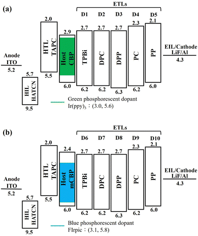
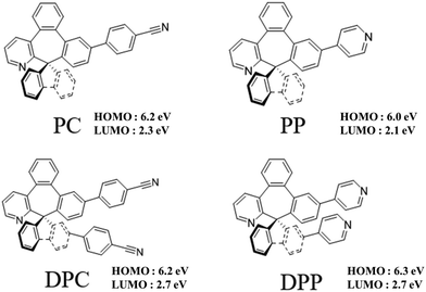
Fig. 1 shows the energy-level diagram of the green and blue OLED devices comprised of the four seven-member-ring-based ETLs, DPC, DPP, PC, and PP, compared against that of the TPBi-comprised counterpart. The devices were composed of a 150 nm indium tin oxide (ITO) anode layer, a 3 nm 1,4,5,8,9,11-hexaazatriphenylenehexacarbonitrile (HAT-CN) hole-injection layer (HIL), a 35 nm 1,1-bis[(di-4-tolylamino)phenyl]cyclohexane (TAPC) hole-transporting layer (HTL), (a) a 11 nm EML with green dopant tris(2-phenylpyridine)iridium (Ir(ppy)3) doped in a 4,4′-bis(N-carbazolyl)-1,1′-biphenyl (CBP) host or (b) a 11 nm EML with blue dopant bis[2-(4,6-difluorophenyl)pyridinato-C2,N](picolinato)iridium (FIrpic) doped in a 3,3′-di(9H-carbazol-9-yl)-1,1′-biphenyl (mCBP) host, a 40 nm ETL, a 1 nm lithium fluoride (LiF) electron-injection layer (EIL), and a 100 nm aluminum (Al) cathode layer.Fig. 2 shows the molecular structures of the ETMs PC, PP, DPC, and DPP used for the study.
2.2 Device efficiency and lifetime characterization
A Keithley 2400 electrometer and a Minolta CS-100 luminance meter were used to measure the current–voltage (I–V) characteristics of the OLEDs. The Commission Internationale de l'Eclairage (CIE) coordinates were determined and electroluminescent (EL) spectra obtained by using a Photo Research PR-655 spectroradiometer.The lifetimes of the studied devices encapsulated in a nitrogen purge glove box were measured with a Chroma lifetime test system (Model 58131). The accelerated lifetime testing was conducted at a constant current with a corresponding initial luminance of 5000 cd m−2. The lifetime was based on the T50 (the time for the brightness to drop to 50% of its initial magnitude) of the pristine device.
2.3 Simulation
The recombination rate of the studied OLEDs was obtained by using electrical simulation software SETFOS 4.6 (Fluxim AG). The parameters input for the simulation are listed in Table 1. They include the HOMOs, LUMOs, electron mobilities, and hole mobilities of the organic layers, namely HIL, HTL, EML, and ETL. Also input were the work functions of the inorganic layers, including an anode (−5.2 eV) and a composite layer of electron injection material with aluminum (Al) (−4.2 eV).The simulated device structure consisted of a 150 nm ITO anode layer, a 3 nm HAT-CN HIL, a 35 nm TAPC HTL, an 11 nm EML, a 40 nm ETL, a 1 nm LiF EIL, and a 100 nm Al cathode layer.
2.4 Material characteristic measurements
The electron mobility of DPP, DPC, PP, and PC can be obtained by measuring the current density and the voltage of electron-only device (EOD) and using them in the following equation. The result is shown in Table 2.where J is the current density; εr is the relative dielectric constant of organic material; ε0 is the dielectric constant of vacuum; μ is the electron mobility of organic material; V is the voltage; L is the thickness of the organic film.
| ETM | μ e (× 10−5 cm2 V−1 s−1) | Abs. λmaxb, nm | Em. λmaxb, nm (fwhm)c | E ox/Eredd, V | HOMOe, eV | LUMOf, eV | E T , eV | E g , eV | Molecular weight, g mol−1 | T g/Tm/Td, °C |
|---|---|---|---|---|---|---|---|---|---|---|
| a Under electric field of 1000 (V cm−1)1/2. b Measured in toluene. c Full width at half-maximum, fwhm. d Electrochemical data of materials Eox and Ered were measured in CH2Cl2 (1 mM) and DMF (1 mM), respectively, in the presence of 0.1 M Bu4N+PF6−, using glassy carbon as a working electrode and Pt as counter electrode with a scan rate of 250 mV s−1, and potentials are quoted with reference to the internal ferrocene standard. e E HOMO = −(Eox,onset + 5.1). f E LUMO = Eg + EHOMO. g Calculated from the onset of the absorption spectrum. h Estimated from the highest energy peak of the phosphorescence spectra at 77 K in 2-Me-THF. i Measured in film. | ||||||||||
| TPBi | 2.260 | — | — | — | 6.255 | 2.755 | 2.6758 | 3.555 | 409 | 12459/—/— |
| DPP | 7.2a | 291/291i | 363(48), 384(95)i | 1.20/−2.51, −2.64 | 6.3 | 2.7 | 2.54 | 3.61 | 548 | 181/—/381 |
| DPC | 9.3a | 329/297i | 378(48), 398(70)i | 1.07/−2.39 | 6.2 | 2.7 | 2.41 | 3.48 | 596 | 188/—/442 |
| PP | 0.13a | 291/290i | 325(32), 374(153)i | 0.91/−2.56, −2.83 | 6.0 | 2.1 | 2.84 | 3.90 | 471 | 155/319/370 |
| PC | 0.62a | 297/294i | 366(60), 366(44)i | 1.06/−2.39, −2.85 | 6.2 | 2.3 | 2.67 | 3.84 | 495 | 153/291/388 |
Glass transition temperatures of the four seven-member-ring materials were measured by using a Mettler-Toledo 2-HT thermal analyzer, carried out in a nitrogen atmosphere at a ramp rate of 10 °C min−1.
3. Results and discussion
3.1 Characteristics of the ETMs
Table 2 shows the thermal, photophysical, and electrochemical characteristics of the four seven-member-ring-based ETMs, compared against those of the typical TPBi.The electrochemical properties of the studied ETMs were measured by cyclic voltammetry (CV). The HOMO energy levels of the hosts were estimated to be 6.3 eV, 6.2 eV, 6.0 eV, and 6.2 eV for DPP, DPC, PP, and PC, respectively, using oxidation potential. The LUMO energy levels were calculated to be 2.7 eV, 2.7 eV, 2.1 eV, and 2.3 eV for DPP, DPC, PP, and PC, respectively, from HOMO energy levels and optical energy band gaps, which were estimated from the edge of the absorption spectra.
3.2 Green OLEDs and device efficiency
Table 3 shows the PE, OV, CE, EQE, CIE coordinates, and maximum luminance of the green OLED devices comprised of the four seven-member-ring-based ETMs, namely DPC, DPP, PC, and PP, compared against those of the TPBi-comprised counterpart. Fig. 3 shows the effect of the studied ETMs on the (a) power efficacy, (b) current efficacy, and (c) external quantum efficiency of the studied green OLEDs. As seen, the DPP-containing device yielded the best performance. At 1000 cd m−2, for example, the PE was increased from 23 to 32 lm W−1, an increase of 39%, CE from 32 to 39 cd A−1, an increase of 22%, and EQE from 8.7 to 11%, an increase of 26%, when DPP was used in lieu of TPBi.| ETM | @ 100/1000/10![[thin space (1/6-em)]](https://www.rsc.org/images/entities/char_2009.gif) 000 cd m−2 000 cd m−2 |
Max. luminance (cd m−2) | ||||
|---|---|---|---|---|---|---|
| Operation voltage (V) | Power efficacy (lm W−1) | Current efficacy (cd A−1) | EQE (%) | CIE coordinates (x, y) | ||
| TPBi | 3.2/4.4/7.5 | 36.8/22.5/11.7 | 37.7/31.5/27.7 | 10.5/8.7/7.7 | (0.33, 0.61)/(0.33, 0.61)/(0.33, 0.61) | 64![[thin space (1/6-em)]](https://www.rsc.org/images/entities/char_2009.gif) 420 420 |
| DPC | 2.6/3.4/7.2 | 46.8/28.9/8.2 | 38.3/30.8/18.8 | 10.6/8.6/5.2 | (0.33, 0.61)/(0.33, 0.61)/(0.33, 0.62) | 43![[thin space (1/6-em)]](https://www.rsc.org/images/entities/char_2009.gif) 470 470 |
| DPP | 3.1/3.9/7.0 | 44.5/31.9/14.7 | 43.5/39.2/32.6 | 12.1/10.9/9.0 | (0.33, 0.62)/(0.33, 0.62)/(0.33, 0.62) | 61![[thin space (1/6-em)]](https://www.rsc.org/images/entities/char_2009.gif) 800 800 |
| PC | 3.5/5.2/9.5 | 37.8/21.5/8.5 | 36.8/32.0/23.1 | 10.3/8.9/6.4 | (0.34, 0.61)/(0.33, 0.61)/(0.33, 0.61) | 40![[thin space (1/6-em)]](https://www.rsc.org/images/entities/char_2009.gif) 900 900 |
| PP | 5.0/7.1/11.5 | 23.9/13.8/6.9 | 34.1/27.8/22.8 | 9.5/7.8/6.4 | (0.33, 0.61)/(0.33, 0.61)/(0.34, 0.61) | 29![[thin space (1/6-em)]](https://www.rsc.org/images/entities/char_2009.gif) 900 900 |
 | ||
| Fig. 3 Effect of the studied ETMs on the (a) power efficacy, (b) current efficacy, and (c) external quantum efficiency of the studied green OLEDs. | ||
The reason why the DPP-containing device exhibited the best efficiency performance may be attributed to the two efficiency effective factors, i.e. a deeper hole blocking barrier between the DPP ETL and host and a higher electron mobility of the DPP.
3.3 Lifetime of the green OLED devices
Fig. 4 shows the lifetime performance of the green OLED device with the seven-member-ring-based DPP compared against that with the typical TPBi counterpart, at an initial luminance of 5000 cd m−2. The device lifetime was increased from 1.4 to 2.0 h, an increase of 43%, when the typical TPBi-composed counterpart was replaced by DPP. The lifetime enhancement may be attributed to the high glass transition temperature of DPP (181 °C), which was 124 °C for TPBi. Besides, DPP had a higher molecular weight (548 g mol−1) than TPBi (409 g mol−1) which may prevent molecular diffusion during device operation and hence a longer device lifetime was observed.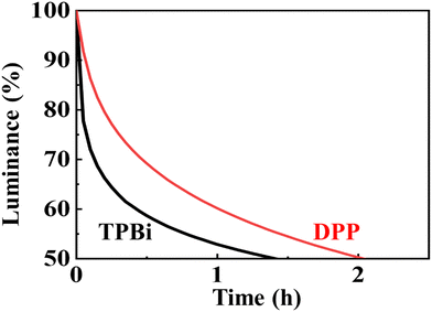 | ||
| Fig. 4 Lifetime performance of the green OLED with the seven-member-ring-based DPP compared against that with the typical TPBi counterpart, at an initial luminance of 5000 cd m−2. | ||
TGA of the materials was conducted to determine their thermal stabilities in view of their thermal decomposition temperatures (Td), which are preferably at least 20 degrees above the vacuum deposition temperature of a given material. Materials with high glass transition temperature often possess satisfactory amorphous film-forming properties and avoid local crystallization problems during operational heating and cooling events, that lead to tip discharge or film detachment and eruption of device performance. The Td values are well above 350 °C, falling in the ranges of 370–388 °C and 381–442 °C, respectively, in PC/PP and DPC/DPP, presumably due to increased molecular weight and π–π stackings. The Tg values are well above 100 °C and fall in the ranges of 153–155 °C and 181–188 °C, respectively, in PC/PP and DPC/DPP. Namely, the double-arm materials possess Tg higher by 20–30 °C than those of the single-arm ones.
3.4 Electrical simulation of the green OLED devices
Fig. 5 shows the effect of ETM electron mobility on the recombination rates of the green OLED devices composed of the seven-member-ring-based DPP and the typical TPBi by using a simulation tool of SETFOS. DPP has an electron mobility of 7.2 × 10⁻⁵ cm2 V−1 s−1 under an electric field of 1000 (V cm−1)1/2 which is 3 times that of TPBi (2.2 × 10⁻⁵ cm2 V−1 s−1). The resulting recombination rate is 204 cm−3 s−1 for the DPP-containing green device, which is 5 times that of the TPBi counterpart (40 cm−3 s−1). It is noteworthy that the above recombination rates were calculated according to the total area of the peaks within the EML. The higher electron mobility can be used to explain at least partly why the device containing DPP showed a better efficiency performance than the typical TPBi-containing counterpart.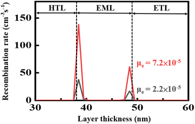 | ||
| Fig. 5 Effect of ETM electron mobility on the recombination rates of the green OLED devices containing the seven-member-ring-based DPP and the typical TPBi. | ||
When the square root of the applied electric field is 1100 (V cm−1)1/2, the decreasing order of the electron mobility (i.e., electron hopping rate) is as follows: DPC > DPP > PC > PP (Table 4). Notably, the relative rate of electron hopping is in a ratio of 10.0/1.00 (p-PhCN/ppy), which is proportional to the electron-accepting ability in the PC and PP series. On the other hand, the relative rates of electron hopping in double-arm DPC and DPP series are 13 and 85 times faster than in the cases of PC and PP, respectively.
| Compound | Electric field (V cm−1)1/2 | Electron mobility (cm2 V−1 s−1) |
|---|---|---|
| PC | 1100 | 1.1 × 10⁻⁵ |
| PP | 1100 | 1.3 × 10⁻⁶ |
| DPC | 1100 | 1.5 × 10⁻⁴ |
| DPP | 1100 | 1.1 × 10⁻⁴ |
| ppys | 1100 | 6.5 × 10⁻⁴ |
These results in Fig. 6 strongly indicate that electron-hopping events may proceed through the same consecutively stacked PC templates or alternating stacked templates of topPhCN/bottomPhCN with DPC being 13 times more efficient. Remarkably, in the case of pyridine as the acceptor, the electron hopping through the alternating stacked templates of topppy/bottomppy in DPP is the key hopping mechanism and works as efficiently as in the case of DPC.
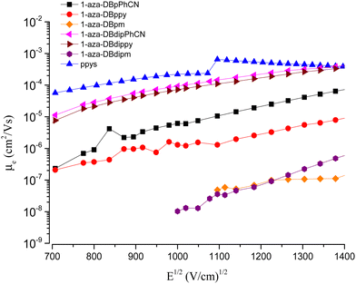 | ||
| Fig. 6 Stacked plot for the correlation of electron mobility with the square root of electric field for EOD based on the ETMs and compared with ppys. | ||
Fig. 7 shows the effect of HOMO level on the recombination rate of the green OLED devices composed of the seven-member-ring-based DPP and the typical TPBi. DPP has a HOMO level of −6.3 eV which is deeper than that of TPBi (−6.2eV). Taking the application of a 10 V forward bias for example, the recombination rate for the DPP-containing green device is 65 cm−3 s−1, 15% higher than that for the TPBi-containing counterpart (55 cm−3 s−1).
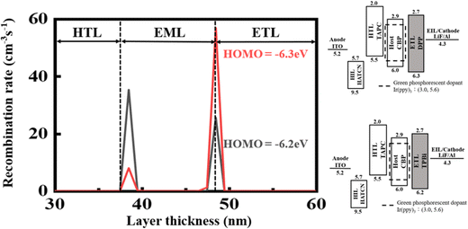 | ||
| Fig. 7 Effect of ETM HOMO level on the recombination rates of the green OLED devices composed of the seven-member-ring-based DPP and the typical TPBi. | ||
The higher recombination rate mentioned above may be due to a higher hole blocking barrier between DPP and the host of the EML, which is 0.3 eV, while being 0.2 eV for the TPBi-containing counterpart. As shown in Fig. 8, a higher hole blocking barrier, formed at the ETL/EML interface, could lead to less overflow for the holes to further transport from the host in the EML to the ETL. These considerations might be used to explain why the DPP-containing green device exhibits a higher efficiency.
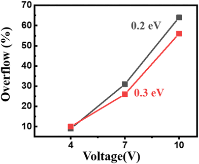 | ||
| Fig. 8 Effect of the hole blocking barrier formed at the ETL/EML interface on the overflow of holes at various applied voltages. | ||
3.5 Blue OLEDs and device efficiency
Table 5 shows the PE, CE, EQE, CIE coordinates, and maximum luminance of the blue OLED devices containing the four seven-member-ring-based ETMs, namely DPC, DPP, PC, and PP, compared against those of the TPBi-containing counterpart. Fig. 9 shows the effect of the studied ETMs on the (a) power efficacy, (b) current efficacy, and (c) external quantum efficiency of the studied blue OLEDs. As seen, the PC-containing device exhibited the best performance at least from 100 to 1000 cd m−2. At 100 cd m−2 for example, the PE was increased from 13 to 19 lm W−1, an increase of 46%, CE from 16 to 25 cd A−1, an increase of 56%, and EQE from 7 to 11%, an increase of 56%, when PC was used in lieu of TPBi.| ETM | @ 100/1000/10![[thin space (1/6-em)]](https://www.rsc.org/images/entities/char_2009.gif) 000 cd m−2 000 cd m−2 |
Max. luminance (cd m−2) | ||||
|---|---|---|---|---|---|---|
| Operation voltage (V) | Power efficacy (lm W−1) | Current efficacy (cd A−1) | EQE (%) | CIE coordinates (x, y) | ||
| TPBi | 3.9/5.1/8.9 | 13.1/8.8/3.9 | 16.2/14.3/11.1 | 7.3/6.4/4.8 | (0.17, 0.37)/(0.17, 0.38)/(0.18, 0.39) | 19![[thin space (1/6-em)]](https://www.rsc.org/images/entities/char_2009.gif) 910 910 |
| DPC | 3.7/5.7/10.0 | 8.5/6.6/2.2 | 10.0/11.9/7.0 | 4.5/5.2/3.0 | (0.17, 0.36)/(0.17, 0.36)/(0.18, 0.37) | 14![[thin space (1/6-em)]](https://www.rsc.org/images/entities/char_2009.gif) 600 600 |
| DPP | 3.9/5.6/10.0 | 11.1/7.1/2.6 | 13.6/12.8/8.3 | 6.0/5.7/3.6 | (0.17, 0.38)/(0.17, 0.37)/(0.18, 0.38) | 15![[thin space (1/6-em)]](https://www.rsc.org/images/entities/char_2009.gif) 320 320 |
| PC | 4.1/6.3/11.3 | 18.7/9.1/2.8 | 24.5/18.3/10.0 | 10.9/8.1/4.4 | (0.17, 0.38)/(0.17, 0.38)/(0.18, 0.37) | 14![[thin space (1/6-em)]](https://www.rsc.org/images/entities/char_2009.gif) 110 110 |
| PP | 5.3/7.7/13.5 | 12.1/5.8/1.8 | 14.7/12.9/7.1 | 6.5/5.6/3.1 | (0.16, 0.36)/(0.17, 0.37)/(0.18, 0.39) | 11![[thin space (1/6-em)]](https://www.rsc.org/images/entities/char_2009.gif) 860 860 |
 | ||
| Fig. 9 Effect of the studied ETMs on the (a) power efficacy, (b) current efficacy, and (c) external quantum efficiency of the studied blue OLEDs. | ||
The reason why the PC-containing device exhibited the best efficiency amongst all the four studied ETLs may be attributed to three efficiency effective factors, i.e. high electron mobility, high triplet energy, and effective energy transfer between PC and sky-blue dopant FIrpic.
Fig. 10 shows the photoluminescence (PL) spectra of the ETMs PC and TPBi. Also shown, the UV-visible spectrum of the sky-blue dopant FIrpic overlapped with the PL of PC (9.2%) more than with that of TPBi (7.6%). This may explain partly why the PC-containing green device exhibited a better device performance as compared against the TPBi-containing counterpart, at least from 100 to 1000 cd m−2.
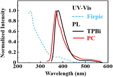 | ||
| Fig. 10 Photoluminescence (PL) spectra of the ETMs PC and TPBi. Also shown is the UV-visible spectrum of the sky-blue dopant FIrpic. | ||
3.6 Blue OLED device lifetime
Fig. 11 shows the lifetime performance of the blue OLED device with the seven-member-ring-based PC compared against that with the typical TPBi-containing counterpart at 1000 cd m−2. The device lifetime was decreased from 1.2 to 0.9 h, a decrease of 25%, when TPBi was replaced by PC. The decrease may be attributed to the high electron injection barrier at the ETL/cathode interface. PC has a LUMO level of −2.3 eV which is much higher than that of TPBi (−2.7 eV). The electrons might be blocked at the ETL/cathode interface, generating high Joule heating and hence a shorter device lifetime as observed. Joule heating causes thermal expansion, inter-layer diffusion and crystallization or melting of organic materials, which limit the lifespan of devices.61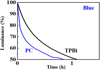 | ||
| Fig. 11 Lifetime performance of the blue OLED with the seven-member-ring-based PC compared against that with the typical TPBi counterpart, at an initial luminance of 1000 cd m−2. | ||
3.7 Electrical simulation of blue OLED devices
Fig. 12 shows the effect of ETM electron mobility on the recombination rates of the blue OLED devices containing the seven-member-ring-based PC and the typical TPBi. Upon applying a 10 V forward bias for example, PC that has a lower electron mobility, 0.62 × 10⁻⁵ cm2 V−1 s−1 under an electric field of 1000 (V cm−1)1/2, could enable a recombination rate only 30% that of the TPBi-containing counterpart. This is because the electron mobility of TPBi is 2.2 × 10⁻⁵ cm2 V−1 s−1, almost 4 times faster than that of PC. The lower electron mobility can be used to explain at least partly why the device composed of PC showed a comparatively poorer efficiency performance at high voltage.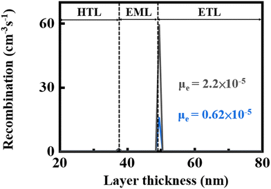 | ||
| Fig. 12 Effect of ETM electron mobility on the recombination rates of the blue OLED devices containing the seven-member-ring-based PC and the typical TPBi upon applying a 10 V forward bias. | ||
Fig. 13 shows the effect of ETM LUMO level on the recombination rates of the blue OLED devices containing the seven-member-ring-based PC and TPBi. Upon applying a 10 V forward bias for example, PC that has a LUMO level of 2.3 eV could enable a recombination rate of only 3.4 × 10⁻⁶ cm−3 s−1, significantly lower than that of the TPBi-containing counterpart (8 cm−3 s−1). This may be due to the higher LUMO which could block many more electrons at the ETL/cathode interface, hence leading to a comparatively poorer efficiency performance at high voltage.
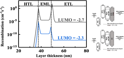 | ||
| Fig. 13 Effect of ETM LUMO level on the recombination rates of the blue OLED devices containing the seven-member-ring-based PC and TPBi upon applying a 10 V forward bias. | ||
Generally speaking, electrons are the minor carriers in the device, and their behaviors dominate the device performance. Increasing the barrier of the cathode/ETL interface can profoundly decrease the injection of electrons and then prevent the formation of excitons and hence decreasing the recombination across the whole device. That is why the device exhibits exponentially lower recombination rates as the LUMO level of ETM continually decreased from −2.3 to −2.7![[thin space (1/6-em)]](https://www.rsc.org/images/entities/char_2009.gif) eV.
eV.
4. Conclusion
To conclude, we demonstrate herein the synthesis of four seven-member-ring-based ETMs, namely DPC, DPP, PC, and PP. By using DPP, a green OLED with a comparatively high efficiency was fabricated. At 1000 cd m−2 for example, the PE was increased from 23 to 32 lm W−1, an increase of 39%, CE from 32 to 39 cd A−1, an increase of 22%, and EQE from 8.7 to 11%, an increase of 26%, when DPP was used in lieu of TPBi. The high efficiency may be attributed to the facts that DPP has an electron mobility (7.2 × 10⁻⁵ cm2 V−1 s−1) higher than that of TPBi (2.2 × 10⁻⁵ cm2 V−1 s−1) and has a HOMO level (−6.3 eV) deeper than that of TPBi (−6.2 eV). The corresponding device lifetime at 5000 cd m−2 was increased from 1.4 to 2.0 h, an increase of 43%. The lifetime enhancement may be attributed to the high glass transition temperature of DPP (181 °C), being 124 °C for TPBi. Besides, DPP had a higher molecular weight (548 g mol−1) than TPBi (409 g mol−1) which may prevent molecular diffusion during device operation and hence a longer device lifetime was observed.For blue OLEDs, the PC-containing device exhibited the best performance from 100 to 1000 cd m−2. At 100 cd m−2 for example, the PE was increased from 13 to 19 lm W−1, an increase of 46%, CE from 16 to 25 cd A−1, an increase of 56%, and EQE from 7 to 11%, an increase of 56%, when PC was used in lieu of TPBi. This may be attributed to a better host-to-guest energy transfer.
Conflicts of interest
There are no conflicts to declare.Acknowledgements
This work was financially supported in part by National Science and Technology Council, Taiwan, ROC, through projects 108-2923-M-007-002-MY3 and 109-2923-M-007-003-MY3. We also gratefully acknowledge the cooperation of Dr Chien-Tien Chen in synthesizing (107-2113-M-007-026-MY3) and providing the studied electron transporting materials. This work was partially supported by the “Frontier Research Centre on Fundamental and Applied Sciences of Matters” from The Featured Areas Research Centre Program within the framework of the Higher Education Sprout Project by the Ministry of Education (MOE) in Taiwan (110QR001I5).References
- Y.-Z. Shi,
et al., High-Performance Nondoped Organic Light-Emitting Diode Based on a Thermally Activated Delayed Fluorescence Emitter with 1D Intermolecular Hydrogen Bonding Interactions, Adv. Opt. Mater., 2021, 9(16), 2100461 CrossRef CAS
.
- H. Sasabe and J. Kido, Development of high performance OLEDs for general lighting, J. Mater. Chem. C, 2013, 1(9), 1699–1707 RSC
.
- N. Thejo Kalyani and S. J. Dhoble, Novel materials for fabrication and encapsulation of OLEDs, Renewable Sustainable Energy Rev., 2015, 44(C), 319–347 CrossRef
.
- S.-J. Zou,
et al., Recent advances in organic light-emitting diodes: toward smart lighting and displays, Mater. Chem. Front., 2020, 4(3), 788–820 RSC
.
- M. Eritt,
et al., OLED manufacturing for large area lighting applications, Thin Solid Films, 2010, 518(11), 3042–3045 CrossRef CAS
.
- R. Meerheim, B. Lussem and K. Leo, Efficiency and stability of pin type organic light emitting diodes for display and lighting applications, Proc. IEEE, 2009, 97(9), 1606–1626 CAS
.
- A. Salehi,
et al., Recent advances in OLED optical design, Adv. Funct. Mater., 2019, 29(15), 1808803 CrossRef
.
- M. C. Gather,
et al., Solution-processed full-color polymer organic light-emitting diode displays fabricated by direct photolithography, Adv. Funct. Mater., 2007, 17(2), 191–200 CrossRef CAS
.
- X. Tang,
et al., Efficient nondoped blue fluorescent organic light-emitting diodes (OLEDs) with a high external quantum efficiency of 9.4%@ 1000 cd m−2 based on phenanthroimidazole− anthracene derivative, Adv. Funct. Mater., 2018, 28(11), 1705813 CrossRef
.
- L. Frédéric,
et al., Maximizing chiral perturbation on thermally activated delayed fluorescence emitters and elaboration of the first top-emission circularly polarized OLED, Adv. Funct. Mater., 2020, 30(43), 2004838 CrossRef PubMed
.
- R. Coehoorn,
et al., Kinetic Monte Carlo study of the sensitivity of OLED efficiency and lifetime to materials parameters, Adv. Funct. Mater., 2015, 25(13), 2024–2037 CrossRef CAS
.
- H. Zhang,
et al., A Multifunctional Blue-Emitting Material Designed via Tuning Distribution of Hybridized Excited-State for High-Performance Blue and Host-Sensitized OLEDs, Adv. Funct. Mater., 2020, 30(35), 2002323 CrossRef CAS
.
- H. S. Kwak,
et al., Design of organic electronic materials with a goal-directed generative model powered by deep neural networks and high-throughput molecular simulations, Front. Chem., 2022, 9, 800370 CrossRef PubMed
.
- M.-G. Shin,
et al., Synthesis and characterization of ortho-twisted asymmetric anthracene derivatives for blue organic light emitting diodes (OLEDs), Dyes Pigm., 2012, 92(3), 1075–1082 CrossRef CAS
.
- Y. Im,
et al., Recent progress in high-efficiency blue-light-emitting materials for organic light-emitting diodes, Adv. Funct. Mater., 2017, 27(13), 1603007 CrossRef
.
- N. A. Kukhta,
et al., Deep-blue high-efficiency TTA OLED using para-and meta-conjugated cyanotriphenylbenzene and carbazole derivatives as emitter and host, J. Phys. Chem. Lett., 2017, 8(24), 6199–6205 CrossRef CAS PubMed
.
- A. Khomyakov,
et al., Effect of high purity molybdenum oxide (vi) on crystal growth and OLED technology., CrystEngComm, 2021, 23(47), 8276–8290 RSC
.
- J.-H. Jou,
et al., Approaches for fabricating high efficiency organic light emitting diodes, J. Mater. Chem. C, 2015, 3(13), 2974–3002 RSC
.
- D. K. Dubey,
et al., Solution process feasible highly efficient white organic light emitting diode, Org. Electron., 2019, 69, 232–240 CrossRef CAS
.
- J. H. Jou,
et al., A replacement for incandescent bulbs: high-efficiency blue-hazard free organic light-emitting diodes, J. Mater. Chem. C, 2017, 5(1), 176–182 RSC
.
- C. Poriel and J. Rault-Berthelot, Blue single-layer organic light-emitting diodes using fluorescent materials: a molecular design view point, Adv. Funct. Mater., 2020, 30(17), 1910040 CrossRef CAS
.
-
W.-Y. Yang, et al., High-Efficiency Organic Light-Emitting Diodes with a Complete Cascading Carrier Injection Structure, 2018 25th International Workshop on Active-Matrix Flatpanel Displays and Devices (AM-FPD), IEEE, 2018 Search PubMed
.
- J.-H. Jou,
et al., Investigation of charge-transporting layers for high-efficiency organic light-emitting diode, J. Phys. D: Appl. Phys., 2018, 51(45), 454002 CrossRef
.
- Y. Tao,
et al., Multifunctional triphenylamine/oxadiazole hybrid as host and exciton-blocking material: high efficiency green phosphorescent OLEDs using easily available and common materials, Adv. Funct. Mater., 2010, 20(17), 2923–2929 CrossRef CAS
.
- K. Klimes, Z.-Q. Zhu and J. Li, Efficient blue phosphorescent OLEDs with improved stability and color purity through judicious triplet exciton management, Adv. Funct. Mater., 2019, 29(31), 1903068 CrossRef
.
- J.-H. Jou,
et al., High efficiency yellow organic light-emitting diodes with a solution-processed molecular host-based emissive layer, J. Mater. Chem. C, 2013, 1(8), 1680–1686 RSC
.
- D. K. Dubey,
et al., Simple-structured efficient white organic light emitting diode via solution process, Microelectron. Reliab., 2018, 83, 293–296 CrossRef CAS
.
- N. C. Erickson and J. H. Russell, Engineering efficiency roll-off in organic light-emitting devices, Adv. Funct. Mater., 2014, 24(38), 6074–6080 CrossRef CAS
.
- Y. Tao,
et al., Multifunctional triphenylamine/oxadiazole hybrid as host and exciton-blocking material: high efficiency green phosphorescent OLEDs using easily available and common materials, Adv. Funct. Mater., 2010, 20(17), 2923–2929 CrossRef CAS
.
-
G. Gaertner and H. Greiner, Light extraction from OLEDs with (high) index matched glass substrates, Organic Optoelectronics and Photonics III, SPIE, 2008, vol. 6999 Search PubMed
.
- Y.-J. Lee,
et al., A high-extraction-efficiency nanopatterned organic light-emitting diode, Appl. Phys. Lett., 2003, 82(21), 3779–3781 CrossRef CAS
.
- K. Saxena, V. K. Jain and D. S. Mehta, A review on the light extraction techniques in organic electroluminescent devices, Opt. Mater., 2009, 32(1), 221–233 CrossRef CAS
.
- W. H. Koo,
et al., Light Extraction of organic light emitting diodes by defective hexagonal-close-packed array, Adv. Funct. Mater., 2012, 22(16), 3454–3459 CrossRef CAS
.
- D. Zhang,
et al., Sterically shielded electron transporting material with nearly 100% internal quantum efficiency and long lifetime for thermally activated delayed fluorescent and phosphorescent OLEDs, ACS Appl. Mater. Interfaces, 2017, 9(22), 19040–19047 CrossRef CAS PubMed
.
- C.-H. Shih,
et al., A high triplet energy, high thermal stability oxadiazole derivative as the electron transporter for highly efficient red, green and blue phosphorescent OLEDs, J. Mater. Chem. C, 2015, 3(7), 1491–1496 RSC
.
- D. K. Dubey,
et al., High-throughput virtual screening of host materials and rational device engineering for highly efficient solution-processed organic light-emitting diodes, ACS Appl. Mater. Interfaces, 2021, 13(22), 26204–26217 CrossRef CAS PubMed
.
- C.-H. Shih,
et al., A universal electron-transporting/exciton-blocking material for blue, green, and red phosphorescent organic light-emitting diodes (OLEDs), ACS Appl. Mater. Interfaces, 2015, 7(19), 10466–10474 CrossRef CAS PubMed
.
- S.-J. Su,
et al., Structure–Property Relationship of Pyridine-Containing Triphenyl Benzene Electron-Transport Materials for Highly Efficient Blue Phosphorescent OLEDs, Adv. Funct. Mater., 2009, 19(8), 1260–1267 CrossRef CAS
.
- Y. Sun,
et al., A pyridine-containing anthracene derivative with high electron and hole mobilities for highly efficient and stable fluorescent organic light-emitting diodes, Adv. Funct. Mater., 2011, 21(10), 1881–1886 CrossRef CAS
.
- D. Zhang,
et al., Sterically shielded electron transporting material with nearly 100% internal quantum efficiency and long lifetime for thermally activated delayed fluorescent and phosphorescent OLEDs, ACS Appl. Mater. Interfaces, 2017, 9(22), 19040–19047 CrossRef CAS PubMed
.
- D. Zhang,
et al., High-Performance Fluorescent Organic Light-Emitting Diodes Utilizing an Asymmetric Anthracene Derivative as an Electron-Transporting Material, Adv. Mater., 2018, 30(26), 1707590 CrossRef PubMed
.
- H. Ye,
et al., Pyridine-containing electron-transport materials for highly efficient blue phosphorescent OLEDs with ultralow operating voltage and reduced efficiency roll-off, Adv. Funct. Mater., 2014, 24(21), 3268–3275 CrossRef CAS
.
- S.-J. Su,
et al., Tuning Energy Levels of Electron-Transport Materials by Nitrogen Orientation for Electrophosphorescent Devices with an ‘Ideal’Operating Voltage, Adv. Mater., 2010, 22(30), 3311–3316 CrossRef CAS PubMed
.
- J. Jayakumar,
et al., Highly thermal stable electron-transporting materials using triptycene derivatives for OLEDs, Org. Electron., 2021, 88, 106013 CrossRef CAS
.
- A. P. Kulkarni,
et al., Electron transport materials for organic light-emitting diodes, Chem. Mater., 2004, 16(23), 4556–4573 CrossRef CAS
.
- M. Liu,
et al., Hybrid heterocycle-containing electron-transport materials synthesized by regioselective Suzuki cross-coupling reactions for highly efficient phosphorescent OLEDs with unprecedented low operating voltage, Chem. Mater., 2012, 24(20), 3817–3827 CrossRef CAS
.
- W.-C. Chen, Z.-L. Zhu and C.-S. Lee, Organic light-emitting diodes based on imidazole semiconductors, Adv. Opt. Mater., 2018, 6(18), 1800258 CrossRef
.
- X. Yin,
et al., Manipulating the LUMO distribution of quinoxaline-containing architectures to design electron transport materials: Efficient blue phosphorescent organic light-emitting diodes, Org. Electron., 2016, 37, 439–447 CrossRef CAS
.
- Y.-T. Lee,
et al., Simple molecular-engineering approach for enhancing orientation and outcoupling efficiency of thermally activated delayed fluorescent emitters without red-shifting emission, ACS Appl. Mater. Interfaces, 2018, 10(50), 43842–43849 CrossRef CAS PubMed
.
- Y. Wei and C.-T. Chen, Doubly ortho-linked cis-4, 4 ‘-bis (diarylamino) stilbene/fluorene hybrids as efficient nondoped, sky-blue fluorescent materials for optoelectronic applications, J. Am. Chem. Soc., 2007, 129(24), 7478–7479 CrossRef CAS PubMed
.
- R. A. K. Yadav,
et al., Role of molecular orbital energy levels in OLED performance, Sci. Rep., 2020, 10(1), 1–15 CrossRef PubMed
.
- Lu Li,
et al., Ultra-thick inverted green organic light-emitting diodes for high power efficiency over 300 lm/W, Org. Electron., 2022, 101, 106414 CrossRef CAS
.
- Y.-H. Lin,
et al., Sensitizer enabling long lifetime wet-processed candlelight OLEDs, Dyes Pigm., 2022, 206, 110624 CrossRef CAS
.
- Y. Ma,
et al., Improved hole-transporting property via HAT-CN for perovskite solar cells without lithium salts, ACS Appl. Mater. Interfaces, 2015, 7(12), 6406–6411 CrossRef CAS PubMed
.
- J.-H. Jou,
et al., Investigation of charge-transporting layers for high-efficiency organic light-emitting diode, J. Phys. D: Appl. Phys., 2018, 51(45), 454002 CrossRef
.
- J.-W. Kang,
et al., Low roll-off of efficiency at high current density in phosphorescent organic light emitting diodes, Appl. Phys. Lett., 2007, 90(22), 223508 CrossRef
.
- X.-L. Li,
et al., Highly efficient thermally activated delayed fluorescence yellow organic light-emitting diodes with a low efficiency roll-off, J. Mater. Chem. C, 2019, 7(26), 8063–8069 RSC
.
- S.-Y. Takizawa, A. M. Victor and P. Anzenbacher Jr., Phenylbenzimidazole-based new bipolar host materials for efficient phosphorescent organic light-emitting diodes, Chem. Mater., 2009, 21(12), 2452–2458 CrossRef CAS
.
- Z.-Y. Liu,
et al., Solution-processed small molecular electron transport layer for multilayer polymer light-emitting diodes, Synth. Met., 2011, 161(5–6), 426–430 CrossRef CAS
.
- Q. Zhang,
et al., Optimized electron-transport material based on m-terphenyl-diphenylphosphine oxide with the harmonious compatibility of high ET and electron mobility for highly efficient OLEDs, J. Mater. Chem. C, 2017, 5(33), 8516–8526 RSC
.
- P. Tyagi,
et al., Degradation of organic light emitting diode: Heat related issues and solutions, Synth. Met., 2016, 216, 40–50 CrossRef CAS
.
Footnotes |
| † Electronic supplementary information (ESI) available. CCDC 2212105 and 2212106. For ESI and crystallographic data in CIF or other electronic format see DOI: https://doi.org/10.1039/d2ma00974a |
| ‡ These authors contributed equally to this work. |
| This journal is © The Royal Society of Chemistry 2023 |

