 Open Access Article
A review on polymers and their composites for flexible electronics
Lixia
Li
abc,
Lijing
Han
 b,
Haiqing
Hu
*a and
Ruoyu
Zhang
 *b
*b
aKey Laboratory of Rubber-Plastics, Ministry of Education/Shandong Provincial Key Laboratory of Rubber-plastics, School of Polymer Science and Engineering, Qingdao University of Science and Technology, Qingdao, 266042, People's Republic of China. E-mail: hhq@qust.edu.cn
bZhejiang International Scientific and Technological Cooperative Base of Biomedical Materials and Technology, Zhejiang Engineering Research Center for Biomedical Materials, Cixi Institute of Biomedical Engineering, Ningbo Institute of Materials Technology and Engineering, Chinese Academy of Sciences, Ningbo, 315300, People's Republic of China. E-mail: zhangruoy@nimte.ac.cn
cDepartment of Chemistry, Hengshui University, Hengshui, 053000, People's Republic of China
First published on 22nd December 2022
Abstract
Flexible electronics have become an important trend in the information era. Consequently, the utilization of conventional metals and inorganic semiconductors is restricted in flexible devices due to their poor stretchability and adaptability. Thus, currently, it is urgent to find suitable candidates to at least partially replace these traditional components. In this case, polymers and their composites are considered as key materials for the fabrication of flexible electronic devices due to their excellent mechanical and electrical properties in flexible substrates, interfacial bonding, and functional active components. In this study, based on the important application value of polymers and their composites, non-functional materials such as substrate materials and adhesive materials, and functional materials including piezoelectric composites, conductive composites, and dielectric composites are summarized comprehensively. In addition, the structural features, performances, advantages, and disadvantages, as well as the main application scenarios of several common polymers are summarized in detail. Finally, we critically analyze the challenges and present future perspectives regarding polymers and composites for flexible electrics, aiming to realize their real applications.
1 Introduction
With the rapid development of information technology such as 5G, the world is being rebuilt by digital technology. Accordingly, the way of manufacturing, living and exploring is changing deeply and significantly, and thus ‘measurable’ and ‘digital’ are needed everywhere. In this case, the traditional rigid electronic devices based on semiconductors, metals, and inorganic materials cannot satisfy the new requirements, such as flexibility, extendable and wearable.1–6 Alternatively, flexible electronics have been booming in recent years because of their flexibility, wearability, and compatibility, showing great potential in energy collection, flexible displays, flexible sensor electronics, electronic skins, and many other fields. In these flexible devices, polymer materials play a very important role due to their versatile and adjustable properties including flexibility.7–9 Firstly, compared to the traditional manufacture of electronic components, polymers can usually be processed by convenient and low-cost methods. Secondly, the chemical structures of polymers can be rationally designed to adapt to various applications. Thirdly, some polymers also have excellent biocompatibility and stability in the human body, endowing them with health monitoring capability in complicated biological conditions. Consequently, polymers have become one of the most indispensable materials in flexible electronics.10–12To date, exciting achievements have been made in the area of flexible electronics. For the construction of full flexible sensor systems, at least four types of components are required, including a power supply, information display, interactive interface and integrated circuit, and a schematic of the applications of polymers and their composites in flexible electronics is shown in Fig. 1. Many researchers and companies are devoted to the development of these components. As a new type of green power supply, flexible solar cells have attracted significant attention in terms of flexible energy collection devices, which can be used in wearable electronic devices due to their flexibility and portability. Professor Takao Someya's team made an outstanding contribution to the field of flexible solar cells. Recently, they proposed the concept of bendable ultra-thin solar cells using transparent polyimide (PI) as the substrate with a thickness of only 1.3 μm. Due to their good adaptability and tensile capacity, these ultra-thin organic solar cells show great application prospects.13 Another type of important energy device is flexible nanogenerators. Utilizing the piezoelectric properties and semiconductor coupling effect of ZnO nanowires (ZnONWs), Professor Zhonglin Wang's research group successfully converted mechanical energy into electrical energy and developed the world's smallest generator, a piezoelectric nanogenerator, for the first time.14–17 In 2012, polyethylene terephthalate (PET) and PI films with different friction characteristics were assembled into the first friction-type nanogenerator, which effectively improved the electromechanical conversion efficiency and electrical output of the device,14 and the relevant research reports have attracted wide attention from researchers in many areas.15,17,18 Similar to the field of flexible displays, the current mainstream is flexible organic light-emitting diode (OLED) technology, among which active-matrix organic light-emitting diode (AMOLED) displays have become one of the hottest research directions in the field of consumer electronics in the last decade.19 Currently, foldable AMOLED mobile phones represented by Huawei's Mate X series and Samsung's Galaxy Fold series have gone into mass production and become very attractive consumer electronic products.20–22 Furthermore, in the case of soft sensing, many research groups and companies have achieved significant progress. For example, Prof. Zhenan Bao's group has made outstanding achievements.23–25 For instance, they reported the preparation of an electronic skin based on an anion conductor, 1-ethyl-3-methylimidazolium bis(trifluoromethylsulfonyl)imide (EMIM TFSI), which was spin-coated on a stretchable composite electrode film made with Ag nanowires and polystyrene-block-poly(ethylene butylene)-block polystyrene (SEBS). This flexible sensor could simultaneously respond to temperature and stress, and it behaved as electronic skin that could feel warm and tactile like human skin. This electronic skin combined complex functions with related simple construction, which is a milestone in this field.26 Lastly, although the development of flexible devices is noteworthy, integrated circuits are also essential. John A. Rogers's group firstly manufactured a flexible complementary inverter circuit using low-cost, low-temperature casting and micro-contact printing techniques on a plastic substrate.27 Thus far, significant progress has been made in flexible complementary circuits operating at low voltages, which have low power consumption and high noise margin.28
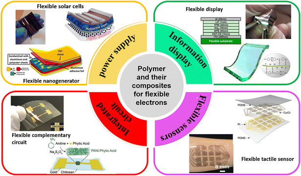 | ||
| Fig. 1 Schematic of the applications of polymers and their composites in flexible electronics. Reproduced with permission ref. 3, 7, 17, 77, 78, 164 Copyright 2021, Elsevier; 2020, Elsevier; 2020, Elsevier; 2020, the American Chemistry Society; 2020, Wiley-VCH; and 2019, Wiley-VCH. | ||
Although polymeric materials show many advantages including flexibility, conformality, and wearable portability, these organic materials still have obvious disadvantages compared with inorganic semiconductors and metal conductors in terms of electrical properties and device stability. Although the power conversion efficiency (PCE) of flexible solar cells has exceeded 19%,29 it is still far lower than that of rigid solar cells.30,31 The energy collection output power of flexible nanogenerators is in the range of milliwatts,32 which can only drive low-cost electronic equipment.33,34 Thus, it is necessary to further improve the energy conversion efficiency and output voltage capacity of piezoelectric polymers. Next, transparent plastic substrates such as PI and PET in flexible display devices all belong to non-crosslinked polymer materials from the viewpoint of molecular architecture. The chain segments and long chains of these non-crosslinked polymer move slowly under external stress, leading to the creep phenomenon, which affects the appearance, feel and service life of the folded display product.21 Besides the creep resistance property, the long-term light transmittance, surface finish and thermal stability of the polymeric matrix need to be further improved to narrow the gap with inorganic glass. The flexible sensing area also faces some challenges, in which the core issue is how to balance the sensitivity and sensing strain range of the sensing material. The key to solve this problem is to choose suitable materials, and among the commonly used materials, conductive polymer composites are outstanding candidates for the flexible strain sensors because of their high mechanical durability, large strain tolerance and adjustable nature.35–37 It has been reported that conductive composites can achieve a high sensing performance through multi-scale structural designs, such as the preparation of double percolation network structures,38 isolation structures,39 and porous structures.40,41 Nevertheless, there are still many challenges such as high sensitivity in a low sensing range and large sensing range with low sensitivity. Another practical problem is that the interface layer can be mismatched between the functional active material and the flexible substrate material during the use of flexible electronic devices, which can lead to the failure of device and affect its service life. In recent years, mussel-inspired hydrogel adhesives have aroused great interest among scientists, where the operating stability and durability of the overall devices can be improved by adopting these polymers.11,42,43 In the case of flexible complementary circuits, there many organic complementary circuits have been reported,44–46 but few studies have been done on flexible substrates to demonstrate fully printed complementary technologies with both high mobility P-type and N-type semiconductors. Briefly, with the increasing demand for flexible electronic products, it is urgent to develop integrated and multi-functional electronic devices, which requires the incorporation of materials science and other disciplines, such as life sciences, machinery, and electronics.
Based on the above discussion, it is known that polymers and their composites have been widely used as non-functional materials such as flexible substrates, adhesive materials, and functional materials such as sensor elements, electrodes, and piezoelectric elements. Considering the great achievement and the existing challenges in polymer-based flexible electronics, it is necessary to review the development of polymers and their composites used in the field of flexible electronics and to provide a reference for researchers in related fields. In this work, several important application directions in flexible devices including solar cells, nanogenerators, displays and sensing are summarized. Furthermore, both non-functional and functional materials including matrix, adhesive materials, conductive composites, piezoelectric composites and dielectric blends are extensively discussed, and the advantages and disadvantages of these candidates are also analyzed. Finally, the existing problems and challenges are presented and the possible methods are proposed.
2 Overview of flexible components
2.1 Flexible energy collection devices
2.2 Flexible displays
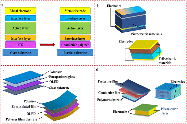
Flexible displays are expected to be thin, light and endure repeatable bending, folding, curling and even stretching. The current mainstream product is the flexible OLEDs.72 OLEDs are stacked on a glass substrate in a specific form and encapsulated with glass or metal plate as in the traditional LED display,73 and a diagram of their structure is shown in Fig. 2c. Compared with the traditional displays, the glass substrate is replaced by a thin and light plastic film in a flexible OLED screen, as shown in Fig. 2c. Currently, flexible OLED screen technology is considered to be one of the most promising next-generation display technologies,74 which can be widely used in consumer electronics such as mobile phones, TVs, wearable devices and vehicle-mounted displays.The flexible plastic film used for the flexible display exhibits reasonable trade-offs in mechanical, optical, and chemical properties, which can be produced by a roll-to-roll process and adapt to high-temperature processing technology.75–77 Nevertheless, compared with inorganic glass, common plastic substrate materials have inferior transparency, high thermal expansion coefficient (CTE),78 permeability to water and oxygen, and easily deformed, which affect the service life of the display, and thus it is necessary to design the molecular structure to improve performance of the polymers and ameliorate technological processes to overcome the existing problems for meeting the increasing demands in society.
2.3 Flexible sensing
Flexible sensors are one of the main forms of flexible electronics, which have become a research hotspot due to their unique advantages such as high sensitivity, durability and biocompatibility.79–81 Strain sensors can be mainly divided into three types, i.e., resistive, capacitive and piezoelectric sensors. Among them, the typical structure of resistive strain sensors contains a conductive film coupled with a flexible substrate, as shown in Fig. 2d. Their basic working principle is that the resistance changes with the deformation of the sensing material, which is reflected as the corresponding change in electrical signal. The core structure of a capacitive sensor is the parallel plate capacitance, as shown in Fig. 2d, which is composed of a dielectric layer in the middle and two parallel electrodes on the two sides. Its basic working principle is that mechanical deformation induced by external stress causes a distance change between the two electrodes, resulting in a variation in capacitance. Compared with resistive and capacitive sensors, piezoelectric pressure sensors are mainly composed of upper and lower electrodes and a middle layer of piezoelectric materials, as illustrated in Fig. 2d, and their working principle is based on the piezoelectric effect.68 When a dielectric material is deformed by external pressure, it will generate internal polarization and an internal electric field, and then an electrical voltage is generated between the two electrodes. The charge is proportional to the applied pressure, which will disappear when the external force is removed.2.4 Flexible complementary circuits
Flexible complementary circuits are widely used in electronic fields, demanding energy supply/dissipation requirements. The typical structure of a flexible complementary circuit includes a P-type and N-type organic thin film transistor (OTFT). The basic working principle is to select the working gate input range to enable only one transistor to be “on”, while the other is “off”. Consequently, the complementary circuits have the advantage of reducing the power consumption by keeping one of the two devices off.44Polymers can play an incomparable role in flexible complementary circuits. Firstly, as the channel layer of OTFT, compared with inorganic and metal oxide semiconductors, conjugated polymers have great advantages in flexibility and solution-processability. Secondly, OTFTs are generally manufactured on polymer substrates because of their broad fabrication methods and excellent flexibility, and their performance is similar to that of devices on silicon substrates without significant attenuation. Lastly, some relatively high molecular weight polymers, such as polystyrene (PS), polymethyl methacrylate (PMMA), PI, and polyvinyl alcohol (PVA) have been used as an organic insulation layer on account of their advantages of solution processing and preparation of ultra-thin films.82
3 Non-functional polymer materials in flexible electronics
Non-functional polymer materials mainly include polymer substrates and adhesive materials. In flexible electronic devices, the active electronic components, whether made of organic, inorganic or hybrid materials, are usually constructed on polymer substrates. Polymer substrates with flexibility/malleability, suitable modulus and insulation not only can play a supporting role, but more importantly, directly determine the flexibility of electronic devices. In addition to polymer substrates, polymer adhesives have been widely used in flexible devices due to their advantages of low cost, simple preparation process, and outstanding bonding effect, which can significantly improve the operating stability and durability of flexible instruments.3.1 Flexible substrates
Plastic and elastomeric substrates are the two most widely used flexible substrates, in which plastic substrates such as PI, PET, and PEN are mainly used in the fields of flexible solar cells and flexible displays. As the supporting matrix, they are required to have good insulation, high strength, excellent bending property, good transparency and temperature resistance. However, in recent years, with the fast development of wearable strain sensors, electronic skins, flexible biomedical devices and flexible electronic devices, plastic substrates cannot satisfy the requirement of free movement.8,9,83 Consequently, elastomeric substrates with high stretchability and elasticity offer the opportunity to address this challenge, and they have become the preferred materials in the above-mentioned applications. The typical elastomers are PDMS and thermoplastic polyurethane (TPU). Table 1 presents a summary of the most common polymer substrates, including their thermal and mechanical properties.| Substrate | T g (°C) | Elongation at break (%) | Young's modulus (MPa) | T max (%) | Applications | Ref. |
|---|---|---|---|---|---|---|
| PET | 68–71 | 1.5–4.0 | 2000–5300 | 80–90 | Flexible displays, flexible organic solar cells, gas sensing | 50, 79, 84 |
| PI | >400 | 8.74 | 2800–4500 | 90 | Flexible organic solar cells, flexible displays | 78, 86 |
| PDMS | −128 to –123 | 200 | 0.5–3 | 87 | Strain sensors | 87, 88 |
| TPU | −32 to −71 | 500–900 | 17–27 | 80 | Strain sensors, capacitive sensors | 89 |
However, the low surface free energy of PET causes difficulty in wettability, adhesion and printability. Thus, various methods have been adopted for the surface modification of PET films, such as chemical modification, heat treatment and plasma treatment.94–96 For example, Chang et al.97 treated a PET film with oxygen plasma to generate active spots on its surface. Moreover, electronic and optoelectronic devices require ultra-clean and smooth surfaces. Zhang and co-authors85 modified the surface of PET using a mild treatment with a moderate acid concentration of a mixture of sulfuric acid and hydrogen peroxide at room temperature. The surface smoothness of PET was significantly improved after this treatment, as shown in Fig. 3a and b. Another challenge associated with PET substrates is their thermal instability. The glass-transition temperature (Tg) of PET is about 71 °C, and its CTE value is 20–80 ppm K−1, which is greater than that of inorganic glass.78 Consequently, they are vulnerable to damage during manufacturing.
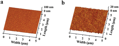 | ||
| Fig. 3 (a) AFM image of the pristine commercial PET substrate. (b) AFM image of PET substrate after smoothing treatment. Reproduced with permission ref. 85. Copyright 2021, The Royal Society of Chemistry. | ||
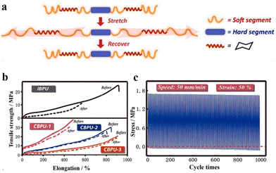 | ||
| Fig. 4 (a) Schematic of the conformational variation of the soft segment and cyclohexane ring under tensile stress. (b) Strain–stress curves of IBPU. (c) Anti-fungal tests and cyclic tensile test of CBPU-3 at 50% strain for 1000 cycles. Reproduced with permission from ref. 110. Copyright 2020, Elsevier. | ||
3.2 Polymeric adhesives
Tight bonding between functional components and flexible substrates is required to ensure device stability and long service life. However, different components have very different mechanical and surficial properties.114 Thus, finding polymeric adhesives that have excellent adhesion strength through chemical bonds is also crucial in flexible devices (covalent bonds, ionic bonds, action of hydrogen bonding, etc.).Polyurethane, PDMS, hydrogels, epoxy resins and polyacrylic esters are the main species of polymeric adhesives. Wong et al.115 developed a polyurethane-based conductive adhesive (PU-ECA) and tested its adhesive strength to paper, PET and PI substrates. The results showed that the PU-ECA layer strongly adhered to flexible substrates and could resist the easement of a commercial tape. Yu et al.116 reported the preparation of a printable tough hydrogel binder in one step using commercial chemicals, where its strong adhesion comes from three orthogonal photochemical reactions (Fig. 5a). It showed excellent adhesion and anti-fatigue capability on different surfaces, and was not sensitive to water, even when submerged under water. Jiang et al.117 developed a high-performance adhesive for combining rigid electronics and deformable circuits based on PDMS elastomer and carbon nanotube/liquid metal co-filler. This conformable adhesive exhibited strong adhesion to the polymer substrate and conductive stability. Compared with the above-mentioned polymer adhesives, epoxy resins and polyacrylic esters have rarely been used due to their rigidity and high hardness.
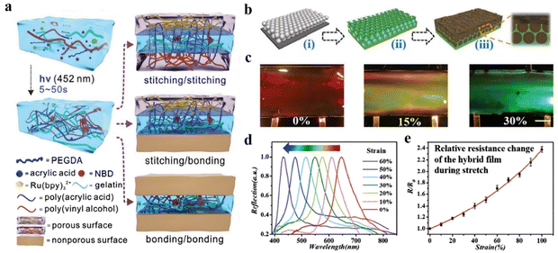 | ||
| Fig. 5 (a) Schematic of preparation of tough multinetwork PTA based on orthogonal Ru(II)/NBD photochemistry. Reproduced with permission from ref. 116. Copyright 2022, Wiley-VCH. (b) Scheme and microstructures of hybrid films. (c) Optical images of the structural color changes of hydrogel hybrid under different strains. (d) Relationship between the reflectance wavelength and stretching intensity. (e) Relative resistance changes of the stretched film. Reproduced with permission from ref. 119. Copyright 2020, Wiley-VCH. | ||
In recent years, inspired by the excellent adhesive properties of marine biological mussels, the study of mussel-inspired adhesives and their applications in flexible electronic devices has attracted wide attention. The foot protein in mussels contains abundant dopamine molecules, which can form thin polydopamine (PDA) coatings on a variety of inorganic and organic materials through polymerization reactions, including intermolecular polymerization and intramolecular polymerization. Fu et al.118 realized strong bonding between AgNW and hydrophobic substrates by adopting PDA-functionalized nanofiber (PDA@NFC) and successfully assembled a double-layer transparent and conductive cellulose-based nanopaper (TCCNP) with good mechanical and chemical stability. Even after 1000 bending cycles and 100 stripping tests, the changes in its photoelectric properties were negligible, implying the stability of the adhesive layer. To date, as a stable binder, PDA has attracted much attention due to its arbitrary deposition capacity and long-term stability. In addition, PDA is considered to be a promising candidate for the design of novel flexible bioelectronic devices with unique contributions both in structure and functionality. Li et al.119 prepared a novel color film with a stretchable, adherent and conductive structure by adding conductive carbon nanotubes/PDA filler to PU reverse opal scaffolds (Fig. 5b and c). The catechol groups on PDA endowed the film with high tissue adhesion and self-healing ability. Notably, due to its responsiveness, the synthesized film could change color in response to motion and be used as a dual-signal soft human motion sensor for real-time color perception and electrical signal monitoring (Fig. 5d).
4 Functional polymeric composites in flexible electronics
Functional polymeric composites in flexible electronics mainly include piezoelectric composites, conductive composites and dielectric composites. Piezoelectric composites can be used as piezoelectric sensors, energy collection and self-powered electron nanogenerators.2,33,120 Conductive composites are potential candidates as strain sensors, which can monitor the strain variation based on resistance change.121 Dielectric composites, incorporating inorganic/organic fillers in the micro/nanometer range with high dielectric constant or polarizability, possess cohesiveness, toughness and workability, as well as high dielectric properties.122–124Table 2 presents a summary of the methods for the preparation of functional polymer composites and their applications.| Polymer matrix | Functional filler | Processing technique | Application | Ref. |
|---|---|---|---|---|
| PDMS | MWCNT | Solution casting | Resistive sensor | 125 |
| PDMS | Graphene Oxide | Casting | Strain sensor | 126 |
| PDMS | BaTiO3/MWCNT | Solution casting | TENG | 127 |
| PDMS | Ag-CNTs-rGO | Template method | Resistive sensor | 128 |
| PDMS | Carbon black | Solution casting | Capacitive sensor | 129 |
| PDMS | ZnO | Solution casting | Piezoelectric sensor | 130 |
| TPU | Carbon black | 3D printing | Strain and tactile sensors | 131 |
| TPU | SWCNT/rGO | Dip-coating process | Strain sensor | 132 |
| TPU | AgNWs/rGO | Electrospinning and Spraying alternately | TENG | 133 |
| TPU | CNS/GNP | Melt processed | Capacitive sensor | 134 |
| SBS | MWCNT | Wet-spinning | Strain sensor | 135 |
| SBS | Graphene | Wet-spinning | Piezoresistive strain sensor | 136 |
| SBS | Ag–Au | Solution casting | Biosensing | 137 |
| SBS | Ag nanoparticles | Electrospinning and situ self-assembly | Electric circuits | 138 |
| PVDF | CNT | Solution mixed | PENG | 139 |
| PVDF | Graphene nanoplatelets | Solution casting | Strain sensor | 140 |
| PVDF | Layered double hydroxides | Spin coating | TENG | 141 |
| PVDF | CsPbBr3 | Electrospinning | PENG | 70 |
| PVDF-HFP | (BaCa)(ZrTi)O3 | Electrospinning | PTNG | 17 |
| PVDF-HFP | BaTiO3 | Solution casting | PENG | 1 |
| PVDF-HFP | ZnO | Electrospinning | Strain sensor | 142 |
| PVDF-TrFE | rGO | Solution mixed and situ polarization | PENG | 143 |
| PVDF-TrFE | Pb (Zr,Ti)O3 | Spin coating | PENG | 71 |
| PVDF-TrFE | MXene | Electrospinning | TENG | 144 |
4.1 Polymeric piezoelectrics
Polymeric piezoelectric materials have found wide application in energy collection devices and self-powered sensors. PVDF and its copolymer, poly(vinylidene fluoride-trifluoroethylene) (P(VDF-TrFE)) and poly(vinylidene fluoride-hexafluoropropylene) (P(VDF-HFP)) are the most commonly used polymers. However, it is difficult for single polymeric piezoelectric materials to meet the requirements of high piezoelectric properties, and thus the introduction of proper fillers becomes inevitable. Besides PVDF and its copolymer, PDMS, PVC, PU, etc. have also been used in the preparation of piezoelectric composites.PVDF-based piezoelectrics combine the advantages of high piezoelectric coefficient of inorganic fillers and the flexibility of PVDF. Generally, these piezoelectric composites can be prepared via melt blending and solution blending, and an external electric field can improve the piezoelectricity of PVDF films. For example, Zhu et al.146 prepared BTO-PVDF/GO core–shell piezoelectric nanofibers with PVDF/GO as the sheath and PVDF/BTO as the core via a coaxial electrostatic spinning process (Fig. 6a). Electron microscopy (Fig. 6b) showed that BTO nanoparticles (NPs) and GO nanosheets were introduced in the core shell of the composite nanofibers, which effectively enhanced the piezoelectric response and polarization effect. The resulting electronic skin (Fig. 6c) was sensitive in the pressure range of 80–230 kPa with sensitivity of up to 10.89 mV kPa−1 (Fig. 6d) and it could withstand 8500 consecutive operations. In another example, Asadi et al.67 prepared PVDF nanofibers via electrostatic spinning. The hybrid nanofillers were composed of ZnO and reduced graphene oxide (rGO), and the ZnO-modified rGO flakes were doped with PVDF nanofibers. Large rGO flakes are flexible and can be folded inside the fibers to form bead structures (Fig. 6e). By optimizing the amount of hybrid filler, only 0.1% wt% ZnO: rGO hybrid filler was added when the mass ratio was 90![[thin space (1/6-em)]](https://www.rsc.org/images/entities/char_2009.gif) :
:![[thin space (1/6-em)]](https://www.rsc.org/images/entities/char_2009.gif) 10. The output voltage of the nanogenerator prepared by the PVDF nanocomposite fiber was nearly 10-times (Fig. 6f) higher than that of previous PVDF nanocomposite fibers. The PVDF piezoelectric composite nanogenerator was applied to a battery-free cardiac pacemaker, which successfully collected 0.487 μJ (Fig. 6g) of energy per heartbeat, which is much higher than the pacing threshold of the human heart.
10. The output voltage of the nanogenerator prepared by the PVDF nanocomposite fiber was nearly 10-times (Fig. 6f) higher than that of previous PVDF nanocomposite fibers. The PVDF piezoelectric composite nanogenerator was applied to a battery-free cardiac pacemaker, which successfully collected 0.487 μJ (Fig. 6g) of energy per heartbeat, which is much higher than the pacing threshold of the human heart.
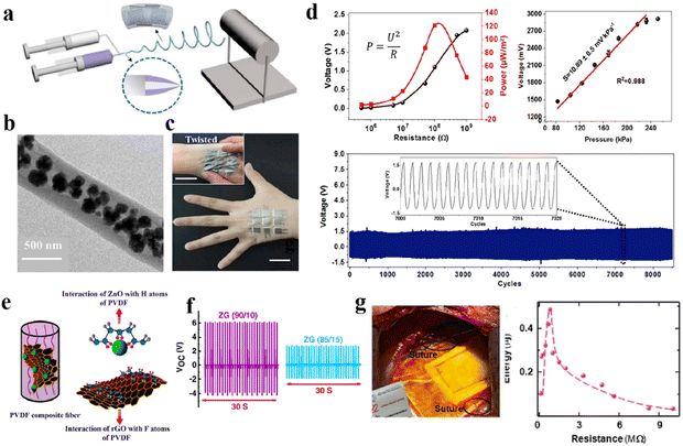 | ||
| Fig. 6 (a) Schematic of the experimental setup for the coaxial electrostatic spinning process. (b) TEM image of a core–shell piezoelectric nanofiber. (c) Optical photograph of electronic skin attached on the back of the hand. (d) Performances of output voltage and sensing stability test. Reproduced with permission from ref. 146. Copyright 2020, Elsevier. (e) Schematic representing dispersion of hybrid nanofillers inside PVDF NFs. (f) VOC values of PNGs. (g) PNG sutured on the epicardium facing the lateral wall of LV (left) and the generated energy of PNG measured across a range of load resistances (right). Reproduced with permission from ref. 67. Copyright 2021, Elsevier. | ||
P(VDF-TrFE) also has excellent spinning ability, where the heat generated in the electrostatic spinning process and the larger charge flow lead to polymer chain stretching, resulting in an α- to β-phase transformation, without any post-treatment.148 Shao et al.149 developed novel P(VDF-TrFE) based electrospinning nanofibers with rGO and loaded MWCNTs, which could be used to manufacture ultra-sensitive piezoelectric pressure sensors. When the content of RGO-MWCNTs as the dopant was 3.2%, the β phase increased to 92% (Fig. 7a). P(VDF-TrFE) nanofibers have high thermal stability due to the increase in their crystallinity. In the variable applied pressure range of 0.25–300 cN, the sensor response increased from 16.125 to 0.430 kPa−1, as shown in Fig. 7b, realizing the ultra-sensitive piezoelectric response of all-organic P(VDF-TrFE) nanofibers. In addition, P(VDF-TrFE) could achieve inherent β-phase crystallization and high piezoelectric properties through a low-temperature quenching process, which has huge energy collection potential. Yu150 employed P(VDF-TrFE) as the matrix, PANI as the conductive filler, and sodium carboxymethyl cellulose (SCMC) as the thickener to prepare a composite aerogel via the freeze-drying method. After thermal treatment, β-phase crystals grew during temperature quenching by liquid nitrogen. As shown in Fig. 7c, the freely moving electrons in PANI (Fig. 7d) could promote charge movement in the material through the conductive network formed between PANI and P(VDF-TrFE). The PTNG prepared using PANI/P (VDF-TrFE) exhibited a maximum output voltage of 246 V and short-circuit current of 122 μA, as shown in Fig. 7e, which could light up 119 blue LEDs in series with a size of 3 mm (Fig. 7f). These results lay the foundation for future research and open up new application prospects.
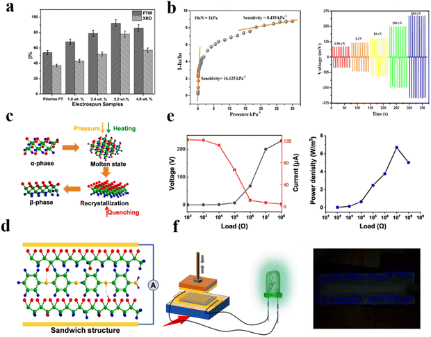 | ||
| Fig. 7 (a) β-phase content of e-spun nanofibrous mat. (b) Sensitivity of the nanocomposite as a sensor under pressure (left) and a voltage (mV) signal of the pressure sensor with varying pressure (right). Reproduced with permission from ref. 149. Copyright 2022, Springer. (c) Schematic of the phase transformation process of PVDF-TrFE. (d) Conductive network between PANI and PVDF-TrFE through hydrogen bonds and dipole interactions. (e) Voltage and current density of the PTNG with different resistances. (f) Load power density with different resistances and connection diagram of PANI/PVDF-TrFE PTNG (left) and 119 LED bulbs (right). Reproduced with permission from ref. 150. Copyright 2021, Elsevier. | ||
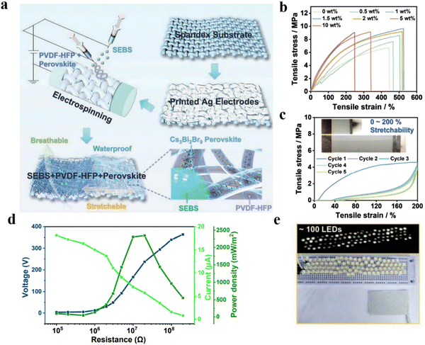 | ||
| Fig. 8 (a) Schematic demonstration of LPPS-NFC for energy harvesting. (b) Tensile stress–strain curves of the LPPS-NFC. (c) Cyclic tensile stress–strain curves. (d) Voltage, current and power density output of LPPS-NFC-based device. (e) LPPS-NFC-based TPENG drove ≈100 LEDs by tapping. Reproduced with permission from ref. 66. Copyright 2022, Wiley-VCH. | ||
Microstructural construction on P(VDF-HFP) could further improve the performances of the device. For example, Lu et al.151 prepared a PVDF-HFP sponge porous structure membrane via solvent-induced phase separation using polyethylene glycol (PEG) as the pore-forming agent and Fe3O4@KH550 as the filler. The device based on this PVDF-HFP nanocomposite membrane exhibited a superior piezoelectric coefficient d33 of 48.6 pC N−1, sensitivity of 294 mV N−1, power density of 5.3 μW cm−3, and power generation performance of more than 10![[thin space (1/6-em)]](https://www.rsc.org/images/entities/char_2009.gif) 000 cycles. The prepared nanogenerator is expected to develop multifunctional responses, high-performance flexible collectors and smart sensors.
000 cycles. The prepared nanogenerator is expected to develop multifunctional responses, high-performance flexible collectors and smart sensors.
4.2 Conductive polymers and polymeric composites
Conductive polymers include intrinsic polymers and complex types. The intrinsic conducting polymers can be further divided into polymeric semiconductors and polymeric conductors based on their conductivity. In the case of P-type polymer semiconductors such as polythiophene (PT), polysilane and pyrrolopyrrolidone (DPP), holes (positive charges) are mainly used as carriers to realize charge transfer between molecules. Alternatively, N-type polymer semiconductors use electrons (negative charges) as carriers to realize charge transfer, and the classical N-type polymers mainly include imide polymers. A polymeric conductor refers to a polymer that can provide carrier or have electrical conductivity after doping. PANI, polypyrrole (PPy), PT and their derivatives (such as PEDOT)154–156 based on the unique π–π conjugate structure are attracting wide interest.Conductive polymeric composites are prepared through various processing technologies (such as solution, melting mix, in situ polymerization, spray, spin coating and dip coating), which combines the flexibility of the polymer matrix and functionality of conductive fillers. PDMS, TPU and SBS are frequently used as the polymeric matrix,88,136,157 while the conductive fillers mainly consist of carbon-based materials (graphite, graphene, CNTs, etc.), metal conductors (silver nanowires/nanoparticles, gold nanosheets and copper nanowires) and conductive polymers (PANI, PPy, and PEDOT: PSS).6,138,158–160 However, although conductive composites have been used for several decades, interestingly there is no generally accepted conclusion about their conductive mechanism to date. Usually, the conducting mechanism is divided into two types, i.e., the tunnel effect and Ohmic conductive law.161 The tunneling effect theory applies quantum mechanics to understand the relationship between the resistivity of materials and the gap of conductive particles. When the content of conductive fillers is low, most of the conductive fillers separately disperse in the resin matrix and cannot form a conductive pathway. When they are isolated by a thin layer of resin, the adjacent conductive fillers will form an energy barrier after an electrical field is applied. Due to the tunneling effect, electrons can undergo a barrier transition and form a current pathway, as shown in Fig. 9. When the concentration of filler is high, the Ohmic conductive law12 will play the major role and conductive paths are formed (Fig. 9).
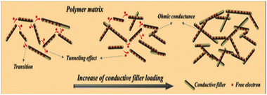 | ||
| Fig. 9 Schematic illustration of the conductive mechanism of polymer conductive composites. Reproduced with permission from ref. 161. Copyright 2018, The Royal Society of Chemistry. | ||
When P3HT is used as the active layer in flexible solar cells, its wide bandgap (∼1.9 eV) and absorption cut-off wavelength at 650 nm limit the overall efficiency. Thus, various acceptors have been designed to improve the photovoltaic performance of P3HT. For example, Sarah Holliday et al.162 presented a new non-fullerene acceptor that was specifically designed to improve the performance together with the wide bandgap of the donor P3HT, and the efficiency of device reached 6.4%, which was the highest value reported for a fullerene-free P3HT. Secondly, the P-type semiconductor P3HT can be used as the active layer of the OTFT by using holes as carriers under the combined action of the gate source voltage and drain–source voltage. P3HT films are usually deposited via the central spin coating method.163 Unfortunately, the resulting orientation of the π-conjugated plane usually shows a mixed state along the vertical and parallel directions, resulting in low crystallinity and current carrier transmission.164 To improve the carrier mobility of the P3HT film in the complementary circuit, Lee et al. fabricated an organic/inorganic hybrid complementary inverter operating at low voltage (1 V or less) by transferring pressed P-type P3HT and inorganic N-type ZnO electrolytic transistors (EGT). The device performance (transfer curves, carrier mobility, on–on voltage, and on/off ratio) clearly demonstrated the excellent reliability of the stamping method for implementing electronic circuits. Lastly, P3HT has been used as a hole injection layer (HIL) of OLEDs to significantly improve their performance.165 Recently, Kim and co-workers166 fabricated an OLED by spinning tris(pentafluorophenyl) borane (BCF)-doped P3HT (P3HT: BCF) nanolayers on ITO electrodes, and then depositing organic layers and top electrodes. The luminance increased dramatically to 26![[thin space (1/6-em)]](https://www.rsc.org/images/entities/char_2009.gif) 910 cd m−2, resulting in a high current efficiency of about 19 cd A−1. They demonstrated that the P3HT: BCF hole injection layer was successfully applied in a flexible OLED.
910 cd m−2, resulting in a high current efficiency of about 19 cd A−1. They demonstrated that the P3HT: BCF hole injection layer was successfully applied in a flexible OLED.
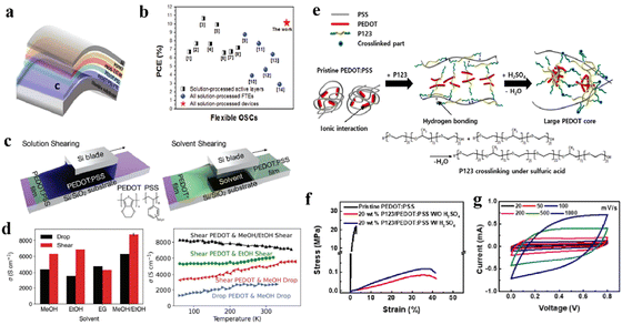 | ||
| Fig. 10 (a) Schematic architecture of all-solution-processed flexible OSCs. (b) Plotted values of PCEs of flexible OSCs reported recently. Reproduced with permission from ref. 63. Copyright 2018, Wiley-VCH. (c) Schematic of sheared deposition of PEDOT: PSS. (d) Typical conductivities of sheared PEDOT: PSS films with post-deposition treatments with different solvents. (d) Temperature dependence of the conductivity of individual deposited PEDOT: PSS films. Reproduced with permission from ref. 173. Copyright 2021, Wiley-VCH. (e) Schematic of the possible scenario in the modification of PEDOT: PSS. (f) Stress–strain curves of free-standing pristine PEDOT: PSS. (g) CV curves of the supercapacitor with a variation in scan rate. Reproduced with permission from ref. 62. Copyright 2018, the American Chemistry Society. | ||
However, an obvious disadvantage of the original PEDOT: PSS film is its low stretchability (<6%).174 It is difficult to maintain both high conductivity and stretchability, and its resistance can be seriously affected by strain. It has been reported that the conductivity of stretchable PEDOT: PSS films can be increased to 2890 S cm−1 using methanesulfonic acid post-treatment, but the resistance increased by 30 times under 30% tensile strain.164 Lee et al.62 modified PEDOT: PSS using the poly(ethylene glycol)-B-poly(propylene glycol)-B-poly(ethylene glycol) triblock copolymer (Fig. 10e), and then used sulfuric acid for post-treatment to prepare a transparent PEDOT: PSS film. The resulting blend showed conductivity of 1700 S cm−1 and good tensile properties (Fig. 10f). The resistance only changed by 4% after 1000 cycles of stretching (Fig. 10g), indicating that the resistance is hardly affected by the deformation. However, there is no intrinsic conductive polymer with high ductility that can be used as a flexible electrode. Thus, the low tensile limit and high manufacturing cost are problems that need to be further solved, and the choice of the composite conductive polymer may be a better choice to realize flexible active elements.
Given that PDMS elastomers are chemically crosslinked, their conductive composites are usually prepared via a simple solution pouring molding method. For example, Fu et al.161 prepared silanized cellulose nanocrystals (SCNC)/CNT nanocrystals via the solution casting method. The SCNC-CNT/PDMS-assembled strain sensor showed a high strain range of more than 100% and had good strain sensitivity, with a gauge factor (GF) of 37.11 at 50 °C, providing long-term stability and durability. To achieve high sensitivity and flexibility, researchers have adopted some special preparation methods to prepare PDMS conductive composites to obtain better comprehensive performances. Hu et al.178 let carbon black nanoparticles (nCB) diffuse in PDMS to form a gradient distribution, as illustrated in Fig. 11a. The mechanical properties of the PDMS/nCB composites obtained were observed to be close to that of pure PDMS, with elongation at break, tensile strength and modulus of 361%, 0.483 MPa and 0.55 MPa, respectively (Fig. 11b). When the nCB content was 6.2 wt%, the GF reached 343 and the strain reached 355%, which could be used as a high-performance flexible strain sensor to detect the finger or facial movements (Fig. 11c). Elizabeth et al.179 manufactured a vertically aligned carbon nanotube (VACNT)/PDMS thin film, and the preparation process is shown in Fig. 11d. A CNT thin film was obtained on an SiO2/Si substrate via the chemical vapor deposition (CVD) method and the PDMS seamlessly permeated in the adjacent VACNT gap. The final device showed attractive properties, with the detectable strain in the range of 0.004% to 30%, GF of 6436.8 (Fig. 11e) under 30% strain, ultra-fast response time of 12 ms, recovery time of 19 ms (Fig. 11f) and excellent reproducibility in 10![[thin space (1/6-em)]](https://www.rsc.org/images/entities/char_2009.gif) 000 cycles (Fig. 11g).
000 cycles (Fig. 11g).
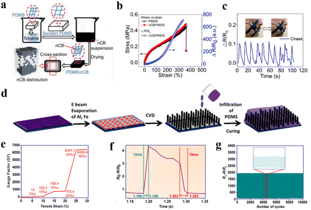 | ||
Fig. 11 (a) Schematic of the procedure for the preparation of PDMS/nCB nanocomposites. (b) Stress and relative resistance change versus strain. (c) Cycled electromechanical behaviors of PDMS/nCB at different speeds of air blowing on the cheek. Reproduced with permission from ref. 178. Copyright 2020, Elsevier. (d) Schematic diagram of the fabrication process of the VACNT/PDMS thin-film. (e) GF as a function of stretchability. (f) Dynamic response time of the VACNT/PDMS thin-film sensor. (g) Electromechanical stability of the VACNT/PDMS thin film for 10![[thin space (1/6-em)]](https://www.rsc.org/images/entities/char_2009.gif) 000 sequential tensile cycles. Reproduced with permission from ref. 179. Copyright 2021, the American Chemistry Society. 000 sequential tensile cycles. Reproduced with permission from ref. 179. Copyright 2021, the American Chemistry Society. | ||
![[thin space (1/6-em)]](https://www.rsc.org/images/entities/char_2009.gif) 000 stretch/release cycles (Fig. 12d).
000 stretch/release cycles (Fig. 12d).
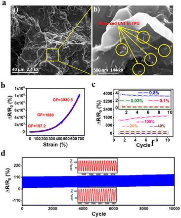 | ||
Fig. 12 (a) SEM images of TPUEM/CNTs/AgNPs. Reproduced with permission from ref. 180. Copyright 2019, Wiley-VCH. (b) ΔR/R0 of CPUF vs strain. (c) Maximum values of CPUF at the strain of 0.03% to 100%. (d) Long-term stability during 10![[thin space (1/6-em)]](https://www.rsc.org/images/entities/char_2009.gif) 000 cycles. Reproduced with permission from ref. 182. Copyright 2022, the American Chemistry Society. 000 cycles. Reproduced with permission from ref. 182. Copyright 2022, the American Chemistry Society. | ||
![[thin space (1/6-em)]](https://www.rsc.org/images/entities/char_2009.gif) 850 S cm−1 (Fig. 13a) and yielded an optimized stretchability of 266% (maximum of 840%) (Fig. 13b). They successfully prepared wearable (Fig. 13c) and implantable electrodes (Fig. 13d) for biosensing and stimulation of human skin and pig heart, respectively. Alternatively, coating, printing and even spinning techniques can be applied to SBS solution. Chen et al.172 prepared SBS/MWCNT cored sheath fibers (SSCCSF) via the coaxial wet spinning method. SEM (Fig. 13e) showed that SSCCSF has a bean-shaped cross-section with SBS as the core and SBS/MWCNTs as the sheath. The SSCCSF sensor exhibited a high sensitivity of 25
850 S cm−1 (Fig. 13a) and yielded an optimized stretchability of 266% (maximum of 840%) (Fig. 13b). They successfully prepared wearable (Fig. 13c) and implantable electrodes (Fig. 13d) for biosensing and stimulation of human skin and pig heart, respectively. Alternatively, coating, printing and even spinning techniques can be applied to SBS solution. Chen et al.172 prepared SBS/MWCNT cored sheath fibers (SSCCSF) via the coaxial wet spinning method. SEM (Fig. 13e) showed that SSCCSF has a bean-shaped cross-section with SBS as the core and SBS/MWCNTs as the sheath. The SSCCSF sensor exhibited a high sensitivity of 25![[thin space (1/6-em)]](https://www.rsc.org/images/entities/char_2009.gif) 832.77 at 41.5% strain, which was capable of detecting large movements in the human body (Fig. 13f) and subtle physiological activities (Fig. 13g). Nevertheless, similar to TPU, the residual strain after large deformation is a significant disadvantage of the SBS conductive composite. Alternatively, the adhesion of SBS has also been utilized. Jeong et al.184 found that the SBS/Au composite could adhere to a chemically crosslinked substrate with good conformability.
832.77 at 41.5% strain, which was capable of detecting large movements in the human body (Fig. 13f) and subtle physiological activities (Fig. 13g). Nevertheless, similar to TPU, the residual strain after large deformation is a significant disadvantage of the SBS conductive composite. Alternatively, the adhesion of SBS has also been utilized. Jeong et al.184 found that the SBS/Au composite could adhere to a chemically crosslinked substrate with good conformability.
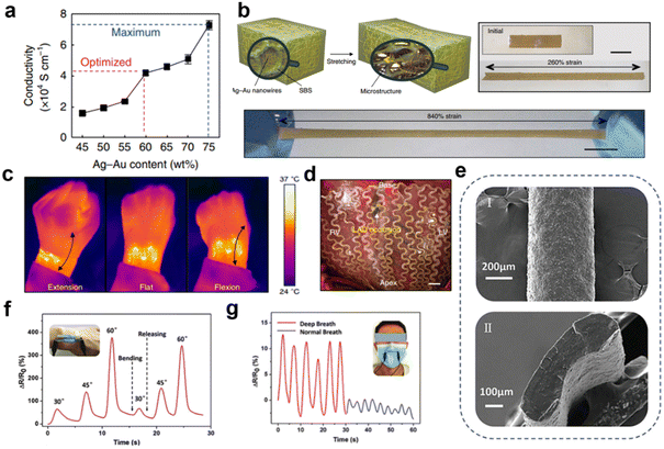 | ||
| Fig. 13 (a)Schematic illustration of the microstructured Ag–Au nanocomposite before and after stretching. (b) Optical image of the Ag–Au nanocomposite. (c) Infrared camera images showing reliable heating performance of the wearable device on a wrist. (d) Optical camera image of implanted cardiac mesh on a swine heart. Reproduced with permission from ref. 137. Copyright 2018, the Author(s). (e) SEM of SBS/MWCNTs core-sheath fiber. (f) Interphalangeal joint bending test. (g) Breathing test. Reproduced with permission from ref. 172. Copyright 2020, Wiley-VCH. | ||
4.3 Polymeric dielectric composites
Polymeric elastomers usually have a low dielectric constant (<10), and the study on polymeric dielectrics with high dielectric constant, low dielectric loss and good flexibility are of great significance.93,185 Similar to the common preparation of composites, dielectric composites are prepared by blending inorganic particles or conductive particles with elastomers.185–187 Currently, the most widely used elastomers are PDMS and TPU, with high dielectric fillers including ferroelectric ceramic fillers such as BTO,124 barium strontium titanate (BST),188 and titanium dioxide (TiO2)189 and conductive fillers including metal nanoparticles and carbon nanomaterials.134,187,190PDMS is the most frequently used dielectric elastomer material for the fabrication of flexible devices due to its excellent elastic properties and biomedical compatibility. For example, Fu et al.190 prepared a flexible capacitive tactile sensor, employing a CNT/PDMS composite film as the dielectric layer, and deposited gold on PI film as the electrode. The sensitivity reached 1.61% kPa−1 at pressures below 1 MPa. The prepared tactile sensor exhibited an ultra-wide pressure operating range of 0.9 kPa–2.55 MPa and excellent stability and fast response time. Alternatively, PDMS can capture negative charge and be decorated with various microstructures, making it a candidate material for the friction layer of triboelectric nanogenerators. Wang et al.30 filled the PDMS matrix with silver nanoparticles and embedded microcapacitors (MCs) and variable microcapacitors (VMCs) in PDMS. Then, a TENG was prepared based on the VMC@PDMS film, which effectively improved the output current. Under 20 m resistance load, the output power density was up to 6 W m−2. This unit could be used to illuminate about 100 green LED in series and exhibited good stability after thousands of cycles.
TPU has also been frequently used. Wang et al.191 incorporated AgNW as a dielectric filler in a TPU nanofiber membrane to construct a composite dielectric layer. The micro-network structure of TPU and AgNW had a synergistic effect and the sensitivity of the capacitive pressure sensor reached 7.24 kPa−1 in the low-pressure range (9.0 × 10⁻³ to 0.98 kPa). TPU foams have also been adopted due to their high porosity, good mechanical flexibility and low compression modulus. Park et al.192 used perovskite derivative oxide (CCTO) to wrap PU sponge with low modulus. The porous PU scaffold reduced the compression modulus and the dielectric constant of the composite was significantly improved. They produced a highly sensitive, stretchable and flexible capacitive sensor with sensitivity of 0.73 kPa−1 (<1.6 kPa), response time of 84 ms, and stability over 7600 cycles.
5 Conclusions and outlook
This review was prepared at a time in which flexible electronics are the focus of both academic research and industry. The purpose of this work is to illustrate the useful polymers for the fabrication of these devices, and, more importantly, to illuminate the features of key materials that are needed for future flexible electronics, which can continuously support their own activities. Based on this consideration, we divided flexible electronics into three parts, including self-sustainable energy power devices, displays and sensors (interaction). Employing these three components, flexible devices can collect data and communicate information. The polymers used in these components can be basically classified into two types based on their functionality, including non-functional polymers (substrates and adhesives) and functional polymeric composites.In the case of non-functional polymers, they are mostly used as substrates and adhesives. Although most polymeric matrices can be feasibly manufactured by traditional techniques, which significantly reduce the cost, their major disadvantages include low heat-resistance capability and anti-fatigue behaviour. Other specific challenges include transparency, gas barrier property, self-healing and biodegradability. One of the most effective ways to meet one or several demands is the molecular design of polymer chains and condensed structures. Nevertheless, this may not be the most economical way. Alternatively, polymeric adhesives have versatile molecular architectures in both industry and academia.
In the case of functional polymeric composites, which act as the key components of power supply, sensor, etc., they can be mostly prepared by solution or melt blending. Not only the species of fillers and polymers can be optimized, but also the processing technique is crucial in increasing the capability of these key materials. Crystallization, microphase separation, dispersion of fillers, and the construction of gradual or pore structures can all be controlled to optimize the overall behaviour of the final device. Together with the above-mentioned limitations originating from the nature of functional polymeric composites.
Among the above-discussed polymers, obviously, PDMS, TPU, PI, PVDF and their derivatives and composites are very important candidates for the preparation of flexible electronics. Nevertheless, in the future, specific polymers with modified or customized properties toward specific applications should be developed. This is because the mechanical properties, sensor range, sensitivity, sustainable power supply, etc. always require better behaviours. Nevertheless, we have sufficient reason to believe that toward long-term flexible electronics, polymers can always find value and irreplaceable roles.
In the case of polymeric substrates, plastic substrates have the disadvantages of low processing temperature, insufficient sealing, poor thermal stability, deformation, etc., and elastomer substrates need further improvement of their fatigue resistance and interface adhesion with functional elements. Their properties should be improved by re-designing the molecular chain structure and microstructure of polymer substrates. Another effective method is to explore new polymers with excellent comprehensive performances to meet higher requirements. In addition, as the requirements of flexible electronics gradually increase, biodegradable substrates, stimuli-responsive substrates, self-healing substrates, and substrates with shape-memory functions have been reported widely, and substrates integrated into multifunctional devices or used in extreme environments also need to be further studied. In the case of polymer adhesive materials, such as mussels-inspired hydrogel adhesives, they have excellent adhesion properties, biocompatibility and self-healing performances, but they are limited to soft systems. Therefore, it is urgent to invest more efforts to extending the current scope to high-hardness and dry systems, such as elastomer adhesives. In addition, novel adhesion enhancement mechanisms and strategies need to be explored to solve the mechanical mismatch problem caused by the different thermal expansion coefficients of different adhesives.
Polymeric composites as functional materials are used in flexible electronic devices including piezoelectric composites, conductive composites and dielectric composites. Firstly, the ferroelectric fatigue of piezoelectric composites is a problem that cannot ignored, and the mechanism of fatigue is not clear at present. Future work should focus on intelligent electronics and biocompatible devices and research on PVDF-based polymer devices may shift attention from basic functions to complex applications. Due to the biocompatibility of PVDF-based polymers, more and more researchers will use them in implantable devices and artificial prosthetics. Secondly, in the case of conductive composites, it is well known that effective conductive networks need a high filler content, which will further reduce the flexibility of the elastic matrix, and thus it is necessary to carry out modifications to optimize the compatibility between the filler and matrix. Alternatively, it is essential to explore new conductive composites through the optimization of molecular design and novel preparation technology to modulate the micro and macro structures. Recently, researchers have started to explore conductive composites by 3D printing, selective laser sintering, two-photon polymerization printing and other new technologies. In addition, it is worth noting that some polymeric semiconductors, such as poly(p-phenylene vinyl) (PPV), poly(furan) (PF) and PT composites have not been explored to date, and it is expected that the development of these materials will yield great application prospects. Lastly, dielectric composites require a high amount of ceramic fillers for improving their dielectric constant, but this is at the cost of mechanical properties. Besides, the dielectric constant is significantly increased at a lower amount of conductive fillers, resulting in high dielectric loss. Therefore, it is necessary to reasonably design the microstructure of composite materials to achieve a reasonable balance of properties and actively explore and develop new dielectric materials and conductive fillers to meet the new demands for flexible electronic products.
Conflicts of interest
There are no conflicts to declare.Acknowledgements
This work was financially supported by The Key Research and Development Program of Zhejiang Province (2019C03074), Ningbo Technological Innovation of 2025 (2020Z086, 2021Z070, 2022Z150), Zhejiang Health Technology Program (2022514106), Ningbo Public Benefit Project (2022S136).References
- A. Bouhamed, Q. Binyu, B. Böhm, N. Jöhrmann, N. Behme, W. A. Goedel, B. Wunderle, O. Hellwig and O. Kanoun, Compos. Sci. Technol., 2021, 208, 108769 CrossRef CAS.
- X. Cao, Y. Xiong, J. Sun, X. Zhu, Q. Sun and Z. L. Wang, Adv. Funct. Mater., 2021, 31, 2102983 CrossRef CAS.
- D. Koo, S. Jung, J. Seo, G. Jeong, Y. Choi, J. Lee, S. M. Lee, Y. Cho, M. Jeong, J. Lee, J. Oh, C. Yang and H. Park, Joule, 2020, 4, 1021–1034 CrossRef CAS.
- Y. Xue, L. Wang, Y. Zhang, G. Liang, J. Chu, B. Han, W. Cao, C. Liao and S. Zhang, IEEE Electron Device Lett., 2021, 42, 188–191 CAS.
- X. Zhao and Z. Ounaies, Nano Energy, 2022, 94, 106908 CrossRef CAS.
- S. Zheng, Y. Jiang, X. Wu, Z. Xu, Z. Liu, W. Yang and M. Yang, Compos. Sci. Technol., 2021, 201, 108546 CrossRef CAS.
- F. De Rossi, G. Renno, B. Taheri, N. Yaghoobi Nia, V. Ilieva, A. Fin, A. Di Carlo, M. Bonomo, C. Barolo and F. Brunetti, J. Power Sources, 2021, 494, 229735 CrossRef CAS.
- K. Sim, Z. Rao, F. Ershad and C. Yu, Adv. Mater., 2020, 32, e1902417 CrossRef.
- I. You, M. Kong and U. Jeong, Acc. Chem. Res., 2019, 52, 63–72 CrossRef CAS.
- W. Kong, Y. Yang, Y. Wang, H. Cheng, P. Yan, L. Huang, J. Ning, F. Zeng, X. Cai and M. Wang, J. Mater. Chem. A, 2022, 10, 2012–2020 RSC.
- S. Li, Y. Cong and J. Fu, J. Mater. Chem. B, 2021, 9, 4423–4443 RSC.
- H. Liu, Q. Li, S. Zhang, R. Yin, X. Liu, Y. He, K. Dai, C. Shan, J. Guo, C. Liu, C. Shen, X. Wang, N. Wang, Z. Wang, R. Wei and Z. Guo, J. Mater. Chem. C, 2018, 6, 12121–12141 RSC.
- X. Xu, K. Fukuda, A. Karki, S. Park, H. Kimura, H. Jinno, N. Watanabe, S. Yamamoto, S. Shimomura, D. Kitazawa, T. Yokota, S. Umezu, T. Q. Nguyen and T. Someya, Proc. Natl. Acad. Sci. U. S. A., 2018, 115, 4589–4594 CrossRef CAS.
- F. R. Fan, Z. Q. Tian and Z. Lin Wang, Nano Energy, 2012, 1, 328–334 CrossRef CAS.
- S. D. Mahapatra, P. C. Mohapatra, A. I. Aria, G. Christie, Y. K. Mishra, S. Hofmann and V. K. Thakur, Adv. Sci., 2021, 8, e2100864 CrossRef PubMed.
- Z. L. W. J. H. Song, Science, 2006, 312, 242–246 CrossRef.
- R. Sahoo, S. Mishra, A. Ramadoss, S. Mohanty, S. Mahapatra and S. K. Nayak, Polymer, 2020, 205, 122869 CrossRef CAS.
- X. Liang, T. Zhao, W. Jiang, X. Yu, Y. Hu, P. Zhu, H. Zheng, R. Sun and C.-P. Wong, Nano Energy, 2019, 59, 508–516 CrossRef CAS.
- S. Sinha, R. Daniels, O. Yassin, M. Baczkowski, M. Tefferi, A. Deshmukh, Y. Cao and G. Sotzing, Adv. Mater. Technol., 2021, 7, 2100548 CrossRef.
- H. Kim, J. Park, T. Khim, S. Bak, J. Song and B. Choi, Sci. Rep., 2021, 11, 8387 CrossRef CAS PubMed.
- H. Wang, X. Yang, S. Zhang, Z. Liu, L. Liu, B. Cai, S. Shi and D. Wang, Chin. J. Liq. Cryst. Disp., 2022, 37, 451–458 Search PubMed.
- Z. H. Yang, C. Q. Kang, H. Q. Guo and L. X. Gao, Acta Polym. Sin., 2021, 52, 1308–1315 Search PubMed.
- L. Beker, N. Matsuhisa, I. You, S. R. A. Ruth, S. Niu, A. Foudeh, J. B. Tok, X. Chen and Z. Bao, Proc. Natl. Acad. Sci. U. S. A., 2020, 117, 11314–11320 CrossRef CAS.
- J. Kang, D. Son, G. N. Wang, Y. Liu, J. Lopez, Y. Kim, J. Y. Oh, T. Katsumata, J. Mun, Y. Lee, L. Jin, J. B. Tok and Z. Bao, Adv. Mater., 2018, 30, e1706846 CrossRef PubMed.
- Y. Khan and Z. Bao, Proc. Natl. Acad. Sci. U. S. A., 2021, 118 Search PubMed.
- I. You, D. G. Mackanic, N. Matsuhisa, J. Kang, J. Kwon, L. Beker, J. Mun, W. Suh, T. Y. Kim, J. B. H. Tok, Z. N. Bao and U. Jeong, Science, 2020, 370, 961 CrossRef CAS PubMed.
- J. A. Rogers, Z. Bao, A. Dodabalapur and A. Makhija, IEEE Elctron Devices Lett., 2000, 21, 100–103 CAS.
- H. Klauk, U. Zschieschang, J. Pflaum and M. Halik, Nature, 2007, 445, 745–748 CrossRef CAS PubMed.
- K. Huang, Y. Peng, Y. Gao, J. Shi, H. Li, X. Mo, H. Huang, Y. Gao, L. Ding and J. Yang, Adv. Energy Mater., 2019, 9, 1901419 CrossRef CAS.
- Afrasiab, A. D. Khan, F. E. Subhan, A. D. Khan, S. D. Khan, M. S. Ahmad, M. S. Rehan and M. Noman, Optik, 2020, 208, 164573 CrossRef CAS.
- Q. Dong, Y. Xue, S. Wang, L. Wang, F. Chen, S. Zhang, R. Chi, L. Zhao and Y. Shi, Sci. China Mater., 2017, 60, 963–976 CrossRef CAS.
- X. Xia, J. Chen, H. Guo, G. Liu, D. Wei, Y. Xi, X. Wang and C. Hu, Nano Res., 2016, 10, 320–330 CrossRef.
- S. Sukumaran, S. Chatbouri, D. Rouxel, E. Tisserand, F. Thiebaud and T. Ben Zineb, J. Intell. Mater. Syst. Struct., 2020, 32, 746–780 CrossRef.
- Y. Wang, L. Zhu and C. Du, Micromachines, 2021, 12, 1278 CrossRef PubMed.
- L. Wang, H. Wang, X.-W. Huang, X. Song, M. Hu, L. Tang, H. Xue and J. Gao, J. Mater. Chem. A, 2018, 6, 24523–24533 RSC.
- S. Wang, P. Xiao, Y. Liang, J. Zhang, Y. Huang, S. Wu, S.-W. Kuo and T. Chen, J. Mater. Chem. C, 2018, 6, 5140–5147 RSC.
- Y. Zhao, M. Ren, Y. Shang, J. Li, S. Wang, W. Zhai, G. Zheng, K. Dai, C. Liu and C. Shen, Compos. Sci. Technol., 2020, 200, 108448 CrossRef CAS.
- Y. Lin, S. Q. Liu, S. Chen, Y. Wei, X. C. Dong and L. Liu, J. Mater. Chem. C, 2016, 4, 6345–6352 RSC.
- M. Wang, K. Zhang, X. X. Dai, Y. Li, J. Guo, H. Liu, G. H. Li, Y. J. Tan, J. B. Zeng and Z. Guo, Nanoscale, 2017, 9, 11017–11026 RSC.
- J. Shen, Y. Guo, S. Zuo, F. Shi, J. Jiang and J. Chu, Nanoscale, 2021, 13, 19155–19164 RSC.
- F. X. Wang, S. H. Zhang, L. J. Wang, Y. L. Zhang, J. Lin, X. H. Zhang, T. Chen, Y. K. Lai, G. B. Pan and L. N. Sun, J. Mater. Chem. C, 2018, 6, 12575–12583 RSC.
- Z. Jin, L. Yang, S. Shi, T. Wang, G. Duan, X. Liu and Y. Li, Adv. Funct. Mater., 2021, 31, 2103391 CrossRef CAS.
- Y. Yang, M. Zhou, J. Peng, X. Wang, Y. Liu, W. Wang and D. Wu, Carbohydr. Polym., 2022, 276, 118753 CrossRef CAS PubMed.
- L. Travaglini, A. P. Micolich, C. Cazorla, E. Zeglio, A. Lauto and D. Mawad, Adv. Funct. Mater., 2020, 31, 2007205 CrossRef.
- Y. Yao, W. Huang, J. Chen, G. Wang, H. Chen, X. Zhuang, Y. Ying, J. Ping, T. J. Marks and A. Facchetti, Proc. Natl. Acad. Sci. U. S. A., 2021, 118, e2111790118 CrossRef CAS.
- G. Cantarella, J. Costa, T. Meister, K. Ishida, C. Carta, F. Ellinger, P. Lugli, N. Münzenrieder and L. Petti, Flexible Printed Electron., 2020, 5, 033001 CrossRef CAS.
- X. Chen, G. Xu, G. Zeng, H. Gu, H. Chen, H. Xu, H. Yao, Y. Li, J. Hou and Y. Li, Adv. Mater., 2020, 32, e1908478 CrossRef.
- J. Kim, D. Ouyang, H. Lu, F. Ye, Y. Guo, N. Zhao and W. C. H. Choy, Adv. Energy Mater., 2020, 10, 1903919 CrossRef CAS.
- Y. Wang, Q. Chen, G. Zhang, C. Xiao, Y. Wei and W. Li, ACS Appl. Mater. Interfaces, 2022, 14, 5699–5708 CrossRef CAS PubMed.
- P. Wen, R. Peng, W. Song, J. Ge, X. Yin, X. Chen, C. Liu, X. Zhang and Z. Ge, Org. Electron., 2021, 94, 106172 CrossRef CAS.
- S. Kim, H. Oh, I. Jeong, G. Kang and M. Park, ACS Appl. Electron. Mater., 2021, 3, 3207–3217 CrossRef CAS.
- J. A. Spechler, T.-W. Koh, J. T. Herb, B. P. Rand and C. B. Arnold, Adv. Funct. Mater., 2015, 25, 7428–7434 CrossRef.
- D. Y. Cho, Y. H. Shin and H. K. Kim, Surf. Coat. Technol., 2014, 259, 109–112 CrossRef CAS.
- X. Dong, P. Shi, L. Sun, J. Li, F. Qin, S. Xiong, T. Liu, X. Jiang and Y. Zhou, J. Mater. Chem. A, 2019, 7, 1989–1995 RSC.
- S. B. Kang, H. J. Kim, Y. J. Noh, S. I. Na and H. K. Kim, Nano Energy, 2015, 11, 179–188 CrossRef CAS.
- H. C. Weerasinghe, P. M. Sirimanne, G. P. Simon and Y. B. Cheng, Prog. Photovoltaics Res. Appl., 2012, 20, 321–332 CrossRef CAS.
- J. Yoon, H. Sung, G. Lee, W. Cho, N. Ahn, H. S. Jung and M. Choi, Energy Environ. Sci., 2017, 10, 337–345 RSC.
- I. Jeon, K. Cui, T. Chiba, A. Anisimov, A. G. Nasibulin, E. I. Kauppinen, S. Maruyama and Y. Matsuo, J. Am. Chem. Soc., 2015, 137, 7982–7985 CrossRef CAS PubMed.
- X. Meng, L. Zhang, Y. Xie, X. Hu, Z. Xing, Z. Huang, C. Liu, L. Tan, W. Zhou, Y. Sun, W. Ma and Y. Chen, Adv. Mater., 2019, 31, e1903649 CrossRef PubMed.
- D. H. Shin, S. W. Seo, J. M. Kim, H. S. Lee and S. H. Choi, J. Alloys Compd., 2018, 744, 1–6 CrossRef CAS.
- H. H. Tang, H. R. Feng, H. K. Wang, X. J. Wang, J. J. Liang and Y. Chen, ACS Appl. Mater. Interfaces, 2019, 11, 25330–25337 CrossRef CAS.
- J. H. Lee, Y. R. Jeong, G. Lee, S. W. Jin, Y. H. Lee, S. Y. Hong, H. Park, J. W. Kim, S. S. Lee and J. S. Ha, ACS Appl. Mater. Interfaces, 2018, 10, 28027–28035 CrossRef CAS PubMed.
- W. Song, X. Fan, B. Xu, F. Yan, H. Cui, Q. Wei, R. Peng, L. Hong, J. Huang and Z. Ge, Adv. Mater., 2018, 30, e1800075 CrossRef PubMed.
- X. Li, C. Jiang, F. Zhao, L. Lan, Y. Yao, Y. Yu, J. Ping and Y. Ying, Nano Energy, 2019, 61, 78–85 CrossRef CAS.
- M. Zhu, M. Lou, J. Yu, Z. Li and B. Ding, Nano Energy, 2020, 78, 105208 CrossRef CAS.
- F. Jiang, X. Zhou, J. Lv, J. Chen, J. Chen, H. Kongcharoen, Y. Zhang and P. S. Lee, Adv. Mater., 2022, 34, e2200042 CrossRef PubMed.
- S. Azimi, A. Golabchi, A. Nekookar, S. Rabbani, M. H. Amiri, K. Asadi and M. M. Abolhasani, Nano Energy, 2021, 83, 105781 CrossRef CAS.
- S. Duan, J. Wu, J. Xia and W. Lei, Sensors, 2020, 20, 2820 CrossRef CAS PubMed.
- Z. Li, M. Zhu, Q. Qiu, J. Yu and B. Ding, Nano Energy, 2018, 53, 726–733 CrossRef CAS.
- H. Chen, L. Zhou, Z. Fang, S. Wang, T. Yang, L. Zhu, X. Hou, H. Wang and Z. L. Wang, Adv. Funct. Mater., 2021, 31, 2011073 CrossRef CAS.
- S. Gupta, R. Bhunia, B. Fatma, D. Maurya, D. Singh, Prateek, R. Gupta, S. Priya, R. K. Gupta and A. Garg, ACS Appl. Energy Mater., 2019, 2, 6364–6374 CrossRef CAS.
- T. Wang, K. Lu, Z. Xu, Z. Lin, H. Ning, T. Qiu, Z. Yang, H. Zheng, R. Yao and J. Peng, Crystals, 2021, 11, 511 CrossRef CAS.
- L. Lee, K. H. Yoon, J. W. Jung, H. R. Yoon, H. Kim, S. H. Kim, S. Y. Song, K. S. Park and M. M. Sung, Nano Lett., 2018, 18, 5461–5466 CrossRef CAS PubMed.
- N. Sun, C. Jiang, Q. Li, D. Tan, S. Bi and J. Song, J. Mater. Sci.: Mater. Electron., 2020, 31, 20688–20729 CrossRef CAS.
- H. Kim, J. Park, S. Bak, J. Park, C. Byun, C. Oh, B. S. Kim, C. Han, J. Yoo, D. Kim, J. Song, P. Choi and B. Choi, Sci. Rep., 2021, 11, 21805 CrossRef CAS.
- F. Qiao, H. Chu, Y. Xie and Z. Weng, Int. J. Energy Res., 2021, 46, 4071–4087 CrossRef.
- J. Tao, R. Wang, H. Yu, L. Chen, D. Fang, Y. Tian, J. Xie, D. Jia, H. Liu, J. Wang, F. Tang, L. Song and H. Li, ACS Appl. Mater. Interfaces, 2020, 12, 9701–9709 CrossRef CAS PubMed.
- Y. Liu, L. Wang, L. Zhao, K. Yao, Z. Xie, Y. Zi and X. Yu, Adv. Electron. Mater., 2020, 6, 1901174 CrossRef CAS.
- W. Li, C. Li, G. Zhang, L. Li, K. Huang, X. Gong, C. Zhang, A. Zheng, Y. Tang, Z. Wang, Q. Tong, W. Dong, S. Jiang, S. Zhang and Q. Wang, Adv. Mater., 2021, 33, e2104107 CrossRef PubMed.
- Z. Zhang, L. Weng, K. Guo, L. Guan, X. Wang and Z. Wu, Ceram. Int., 2022, 48, 4977–4985 CrossRef CAS.
- X. Zhou, L. Zhu, L. Fan, H. Deng and Q. Fu, ACS Appl. Mater. Interfaces, 2018, 10, 31655–31663 CrossRef CAS.
- C. Lu, Z. Ji, G. Xu, W. Wang, L. Wang, Z. Han, L. Li and M. Liu, Sci. Bull., 2016, 61, 1081–1096 CrossRef CAS.
- A. Malik and B. Kandasubramanian, Polym. Rev., 2018, 58, 630–667 CrossRef CAS.
- B. Lu, Y. Wang, B.-R. Hyun, H.-C. Kuo and Z. Liu, IEEE Electron Device Lett., 2020, 1040–1043, DOI:10.1109/led.2020.2994143.
- Z. Zhang, L. Xia, L. Liu, Y. Chen, Z. Wang, W. Wang, D. Ma and Z. Liu, J. Mater. Chem. C, 2021, 9, 2106–2114 RSC.
- M. Qian, X. Mao, M. Wu, Z. Cao, Q. Liu, L. Sun, Y. Gao, X. Xuan, Y. Pan, Y. Niu and S. Gong, Adv. Mater. Technol., 2021, 6, 2100603 CrossRef CAS.
- B. Nie, X. Li, J. Shao, X. Li, H. Tian, D. Wang, Q. Zhang and B. Lu, ACS Appl. Mater. Interfaces, 2017, 9, 40681–40689 CrossRef CAS.
- D. Qi, K. Zhang, G. Tian, B. Jiang and Y. Huang, Adv. Mater., 2021, 33, e2003155 CrossRef.
- F. Li, Z. Xu, H. Hu, Z. Kong, C. Chen, Y. Tian, W. Zhang, W. Bin Ying, R. Zhang and J. Zhu, Chem. Eng. J., 2021, 410, 128363 CrossRef CAS.
- M. Chason, P. W. Brazis, Z. Jie, K. Kalyanasundaram and D. R. Gamota, Proc. IEEE, 2005, 93, 1348–1356 CAS.
- Q. Q. Afzal, K. Jaffar, M. Ans, J. Rafique, J. Iqbal, R. A. Shehzad and M. S. Mahr, Polymer, 2022, 238, 18 CrossRef.
- M. Song, D. S. You, K. Lim, S. Park, S. Jung, C. S. Kim, D. H. Kim, D. G. Kim, J. K. Kim, J. Park, Y. C. Kang, J. Heo, S. H. Jin, J. H. Park and J. W. Kang, Adv. Funct. Mater., 2013, 23, 4177–4184 CrossRef CAS.
- G. Zeng, J. W. Zhang, X. B. Chen, H. W. Gu, Y. W. Li and Y. F. Li, Sci. China: Chem., 2019, 62, 851–858 CrossRef CAS.
- K.-S. Choi, W. A. Braganca Jr, L. Jeong, K.-S. Jang, S. H. Moon, H. C. Bae, Y. S. Eom, M. K. Cho and S. I. Chang, Presented in part at the 2018 IEEE 68th Electronic Components and Technology Conference (ECTC), 2018 Search PubMed.
- R. Get, S. M. Islam, S. Singh and P. Mahala, Microelectron. Eng., 2020, 222, 111200 CrossRef CAS.
- P. Wan, X. Wen, C. Sun, B. K. Chandran, H. Zhang, X. Sun and X. Chen, Small, 2015, 11, 5409–5415 CrossRef CAS PubMed.
- W. S. Chang, T. S. Chang, C. M. Wang and W. S. Liao, ACS Appl. Mater. Interfaces, 2022, 22826–22837, DOI:10.1021/acsami.1c20931.
- Y. Liu, J. Guo, J. Wang, X. Zhu, D. Qi, W. Li and K. Shen, Eur. Polym. J., 2020, 125, 109526 CrossRef.
- X. Wu, C. Shu, X. He, S. Wang, X. Fan, Z. Yu, D. Yan and W. Huang, Macromol. Chem. Phys., 2020, 221, 1900506 CrossRef CAS.
- C. K. Chen, Y. C. Lin, L. C. Hsu, J. C. Ho, M. Ueda and W.-C. Chen, ACS Sustainable Chem. Eng., 2021, 9, 3278–3288 CrossRef CAS.
- S. Miyane, C. K. Chen, Y. C. Lin, M. Ueda and W. C. Chen, ACS Appl. Polym. Mater., 2021, 3, 3153–3163 CrossRef CAS.
- V. Khayrudinov, M. Remennyi, V. Raj, P. Alekseev, B. Matveev, H. Lipsanen and T. Haggren, ACS Nano, 2020, 14, 7484–7491 CrossRef CAS PubMed.
- X. Wang, J. Li, H. Song, H. Huang and J. Gou, ACS Appl. Mater. Interfaces, 2018, 10, 7371–7380 CrossRef CAS PubMed.
- B. You, C. J. Han, Y. Kim, B.-K. Ju and J.-W. Kim, J. Mater. Chem. A, 2016, 4, 10435–10443 RSC.
- C. Wu, X. Tang, L. Gan, W. Li, J. Zhang, H. Wang, Z. Qin, T. Zhang, T. Zhou, J. Huang, C. Xie and D. Zeng, ACS Appl. Mater. Interfaces, 2019, 11, 20535–20544 CrossRef CAS.
- A. Lamberti, S. L. Marasso and M. Cocuzza, RSC Adv., 2014, 4, 61415–61419 RSC.
- Q. Gao, Y. Pan, G. Zheng, C. Liu, C. Shen and X. Liu, Adv. Compos. Hybrid Mater., 2021, 4, 274–285 CrossRef CAS.
- X. Li, J. Yang, W. Yuan, P. Ji, Z. Xu, S. Shi, X. Han, W. Niu and F. Yin, Compos. Commun., 2021, 23, 100586 CrossRef.
- M. H. Behfar, D. D. Vito, A. Korhonen, D. Nguyen, B. M. Amin, T. Kurkela, M. Tuomikoski and M. Mantysalo, IEEE Trans. Compon., Packag., Manuf. Technol., 2021, 11, 1022–1027 CAS.
- W. B. Ying, H. Liu, P. Gao, Z. Kong, H. Hu, K. Wang, A. Shen, Z. Jin, L. Zheng, H. Guo, R. Zhang and J. Zhu, Chem. Eng. J., 2021, 420, 127691 CrossRef CAS.
- C. Ge, G. Wang, X. Li, J. Chai, B. Li, G. Wan, G. Zhao and G. Wang, Compos. Sci. Technol., 2020, 197, 108247 CrossRef CAS.
- S. Li, M. Liu, X. Zhou, Y. Dong and J. Li, Macromol. Mater. Eng., 2021, 306, 2000684 CrossRef CAS.
- S. Yoon, Y. J. Kim, Y. R. Lee, N.-E. Lee, Y. Won, S. Gandla, S. Kim and H.-K. Kim, NPG Asia Mater., 2021, 13, 13–14 CrossRef.
- Y. Xiao, M. Wang, Y. Li, Z. Sun, Z. Liu, L. He and R. Liu, Micromachines, 2021, 12, 1505 CrossRef PubMed.
- Z. Li, R. Zhang, K.-S. Moon, Y. Liu, K. Hansen, T. Le and C. P. Wong, Adv. Funct. Mater., 2013, 23, 1459–1465 CrossRef CAS.
- J. Liu, P. Zhang, H. Wei, Z. Lu and Y. Yu, Adv. Funct. Mater., 2021, 32, 2107732 CrossRef.
- J. Dou, L. Tang, L. Mou, R. Zhang and X. Jiang, Compos. Sci. Technol., 2020, 197, 108237 CrossRef CAS.
- Y. Su, Y. Zhao, H. Zhang, X. Feng, L. Shi and J. Fang, J. Mater. Chem. C, 2017, 5, 573–581 RSC.
- Y. Wang, Y. Yu, J. Guo, Z. Zhang, X. Zhang and Y. Zhao, Adv. Funct. Mater., 2020, 30, 2000151 CrossRef CAS.
- K. Batra, N. Sinha and B. Kumar, Vacuum, 2021, 191, 110385 CrossRef CAS.
- J. Chen, Q. Yu, X. Cui, M. Dong, J. Zhang, C. Wang, J. Fan, Y. Zhu and Z. Guo, J. Mater. Chem. C, 2019, 7, 11710–11730 RSC.
- D. P. Jena, S. Anwar, R. K. Parida, B. N. Parida and N. C. Nayak, J. Appl. Polym. Sci., 2021, 139, 51743 CrossRef.
- L. Ling, F. Liu, J. Li, G. Zhang, R. Sun and C.-P. Wong, Macromol. Chem. Phys., 2018, 219, 1800369 CrossRef.
- F. Wang, Y. Tan, H. Peng, F. Meng and X. Yao, Mater. Lett., 2021, 303, 130512 CrossRef CAS.
- P. Ghahramani, K. Behdinan, R. Moradi-Dastjerdi and H. E. Naguib, Nanotechnol. Rev., 2021, 11, 55–64 CrossRef.
- Y. Tang, Z. Zhao, H. Hu, Y. Liu, X. Wang, S. Zhou and J. Qiu, ACS Appl. Mater. Interfaces, 2015, 7, 27432–27439 CrossRef CAS PubMed.
- S. Feng, H. Zhang, D. He, Y. Xu, A. Zhang, Y. Liu and J. Bai, Energy Technol., 2019, 7, 1900101 CrossRef.
- X. Zhao, F. Meng and Y. Peng, Composites, Part B, 2022, 229, 109466 CrossRef CAS.
- Y. Zhu, X. Chen, K. Chu, X. Wang, Z. Hu and H. Su, Sensors, 2022, 22, 628 CrossRef CAS PubMed.
- K. Jeronimo, V. Koutsos, R. Cheung and E. Mastropaolo, Sensors, 2021, 21, 5873 CrossRef CAS PubMed.
- I. Bozyel, Y. I. Keser and D. Gokcen, Sens. Actuators, A, 2021, 332, 113056 CrossRef CAS.
- Y. Xu, X. Xie, H. Huang, Y. Wang, J. Yu and Z. Hu, J. Mater. Sci., 2020, 56, 2296–2310 CrossRef.
- K. Zhou, Y. Zhao, X. Sun, Z. Yuan, G. Zheng, K. Dai, L. Mi, C. Pan, C. Liu and C. Shen, Nano Energy, 2020, 70, 104546 CrossRef CAS.
- K. Ke, M. McMaster, W. Christopherson, K. D. Singer and I. Manas-Zloczower, Composites, Part A, 2019, 126, 105614 CrossRef CAS.
- W. Li, Y. Zhou, Y. Wang, L. Jiang, J. Ma, S. Chen and F. L. Zhou, Adv. Electron. Mater., 2020, 7, 2000865 CrossRef.
- X. Wang, S. Meng, M. Tebyetekerwa, Y. Li, J. Pionteck, B. Sun, Z. Qin and M. Zhu, Composites, Part A, 2018, 105, 291–299 CrossRef CAS.
- S. Choi, S. I. Han, D. Jung, H. J. Hwang, C. Lim, S. Bae, O. K. Park, C. M. Tschabrunn, M. Lee, S. Y. Bae, J. W. Yu, J. H. Ryu, S. W. Lee, K. Park, P. M. Kang, W. B. Lee, R. Nezafat, T. Hyeon and D. H. Kim, Nat. Nanotechnol., 2018, 13, 1048–1056 CrossRef CAS PubMed.
- M. Park, J. Im, M. Shin, Y. Min, J. Park, H. Cho, S. Park, M. B. Shim, S. Jeon, D. Y. Chung, J. Bae, J. Park, U. Jeong and K. Kim, Nat. Nanotechnol., 2012, 7, 803–809 CrossRef CAS PubMed.
- S. Badatya, D. K. Bharti, N. Sathish, A. K. Srivastava and M. K. Gupta, ACS Appl. Mater. Interfaces, 2021, 13, 27245–27254 CrossRef CAS PubMed.
- H. Cheraghi Bidsorkhi, A. G. D’Aloia, A. Tamburrano, G. De Bellis and M. S. Sarto, Sensors, 2021, 21, 5277 CrossRef CAS PubMed.
- S. Ippili, V. Jella, A. M. Thomas, C. Yoon, J.-S. Jung and S.-G. Yoon, J. Mater. Chem. A, 2021, 9, 15993–16005 RSC.
- G. Y. Li, J. Li, Z. J. Li, Y. P. Zhang, X. Zhang, Z. J. Wang, W. P. Han, B. Sun, Y. Z. Long and H. D. Zhang, Adv. Compos. Hybrid Mater., 2021, 5, 766–775 CrossRef.
- X. Hu, Z. Ding, L. Fei, Y. Xiang and Y. lin, J. Mater. Sci., 2019, 54, 6401–6409 CrossRef CAS.
- S. M. S. Rana, M. T. Rahman, M. Salauddin, S. Sharma, P. Maharjan, T. Bhatta, H. Cho, C. Park and J. Y. Park, ACS Appl. Mater. Interfaces, 2021, 13, 4955–4967 CrossRef CAS PubMed.
- K. Shi, B. Sun, X. Huang and P. Jiang, Nano Energy, 2018, 52, 153–162 CrossRef CAS.
- M. Zhu, M. Lou, I. Abdalla, J. Yu, Z. Li and B. Ding, Nano Energy, 2020, 69, 104429 CrossRef CAS.
- R. Sahoo, S. Mishra, A. Ramadoss, S. Mohanty, S. Mahapatra and S. K. Nayak, Polymer, 2020, 205, 122869 CrossRef CAS.
- Y. Kim, X. Wu, C. Lee and J. H. Oh, ACS Appl. Mater. Interfaces, 2021, 13, 36967–36975 CrossRef CAS PubMed.
- A. Ahmed, Y. Jia, H. Deb, M. F. Arain, H. Memon, K. Pasha, Y. Huang, Q. Fan and J. Shao, J. Mater. Sci.: Mater. Electron., 2022, 33, 3965–3981 CrossRef CAS.
- S. Yu, Y. Zhang, Z. Yu, J. Zheng, Y. Wang and H. Zhou, Nano Energy, 2021, 80, 105519 CrossRef CAS.
- H. Li, W. Lian, T. Cheng, W. Zhang, B. Lu, K. Tan, C. Liu and C. Shen, ACS Sustainable Chem. Eng., 2021, 9, 17128–17141 CrossRef CAS.
- X. Gao, M. Zheng, X. Yan, J. Fu, M. Zhu and Y. Hou, J. Mater. Chem. C, 2019, 7, 961–967 RSC.
- P. Snapp, C. Cho, D. Lee, M. F. Haque, S. Nam and C. Park, Adv. Mater., 2020, 32, e2004607 CrossRef PubMed.
- H. J. Kim, M. Y. Lee, J. S. Kim, J. H. Kim, H. Yu, H. Yun, K. Liao, T. S. Kim, J. H. Oh and B. J. Kim, ACS Appl. Mater. Interfaces, 2017, 9, 14120–14128 CrossRef CAS PubMed.
- I. A. Rashid, M. S. Irfan, Y. Q. Gill, R. Nazar, F. Saeed, A. Afzal, H. Ehsan, A. A. Qaiser and A. Shakoor, Polym. Bull., 2019, 77, 1081–1093 CrossRef.
- M. Wang, P. Baek, A. Akbarinejad, D. Barker and J. Travas-Sejdic, J. Mater. Chem. C, 2019, 7, 5534–5552 RSC.
- M. Amirkhosravi, L. Yue and I. Manas-Zloczower, ACS Appl. Polym. Mater., 2020, 2, 4037–4044 CrossRef CAS.
- Y. Ding, W. Xu, W. Wang, H. Fong and Z. Zhu, ACS Appl. Mater. Interfaces, 2017, 9, 30014–30023 CrossRef CAS PubMed.
- Y. Wang, Z. Yu, G. Mao, Y. Liu, G. Liu, J. Shang, S. Qu, Q. Chen and R.-W. Li, Adv. Mater. Technol., 2019, 4, 1800435 CrossRef.
- S. Zhu, H. Sun, Y. Lu, S. Wang, Y. Yue, X. Xu, C. Mei, H. Xiao, Q. Fu and J. Han, ACS Appl. Mater. Interfaces, 2021, 13, 59142–59153 CrossRef CAS PubMed.
- N. Johner, C. Grimaldi, I. Balberg and P. Ryser, Phys. Rev. B: Condens. Matter Mater. Phys., 2008, 77, 11 CrossRef.
- S. Holliday, R. S. Ashraf, A. Wadsworth, D. Baran, S. A. Yousaf, C. B. Nielsen, C. H. Tan, S. D. Dimitrov, Z. Shang, N. Gasparini, M. Alamoudi, F. Laquai, C. J. Brabec, A. Salleo, J. R. Durrant and I. McCulloch, Nat. Commun., 2016, 7, 11585 CrossRef CAS PubMed.
- K. G. Cho, H. J. Kim, H. M. Yang, K. H. Seol, S. J. Lee and K. H. Lee, ACS Appl. Mater. Interfaces, 2018, 10, 40672–40680 CrossRef CAS PubMed.
- F. De Rossi, G. Renno, B. Taheri, N. Yaghoobi Nia, V. Ilieva, A. Fin, A. Di Carlo, M. Bonomo, C. Barolo and F. Brunetti, J. Power Sources, 2021, 494, 229735 CrossRef CAS.
- S. Lee, H. Kim and Y. Kim, Electronics, 2021, 10, 2283 CrossRef CAS.
- S. Lee, H. Kim and Y. Kim, ACS Appl. Polym. Mater., 2022, 4, 6817–6824 CrossRef CAS.
- Y. H. Kim, C. Sachse, M. L. Machala, C. May, L. Müller-Meskamp and K. Leo, Adv. Funct. Mater., 2011, 21, 1076–1081 CrossRef CAS.
- H. Xu, X. Zhao, G. Yang, X. Ji, X. Zhang, L. Li, B. Wu, X. Ouyang, Y. Ni, L. Chen and H.-C. Hu, Chem. Eng. J., 2022, 430, 133014 CrossRef CAS.
- X. Fan, B. Xu, N. Wang, J. Wang, S. Liu, H. Wang and F. Yan, Adv. Electron. Mater., 2017, 3, 1600471 CrossRef.
- Y. Song, T.-Y. Liu, X.-X. Xu, D.-Y. Feng, Y. Li and X.-X. Liu, Adv. Funct. Mater., 2015, 25, 4626–4632 CrossRef CAS.
- M. Vosgueritchian, D. J. Lipomi and Z. Bao, Adv. Funct. Mater., 2012, 22, 421–428 CrossRef CAS.
- W. Li, Y. Zhou, Y. Wang, L. Jiang, J. Ma, S. Chen and F. L. Zhou, Adv. Electron. Mater., 2020, 7, 2000865 CrossRef.
- A. C. Hinckley, S. C. Andrews, M. T. Dunham, A. Sood, M. T. Barako, S. Schneider, M. F. Toney, K. E. Goodson and Z. Bao, Adv. Electron. Mater., 2021, 7, 2001190 CrossRef CAS.
- U. Lang, N. Naujoks and J. Dual, Synth. Met., 2009, 159, 473–479 CrossRef CAS.
- X. Jing, Z. Ma, M. F. Antwi-Afari, L. Wang, H. Li, H.-Y. Mi, P.-Y. Feng and Y. Liu, Ind. Eng. Chem. Res., 2021, 60, 10419–10430 CrossRef CAS.
- S. M. Mirmohammadi, S. Hoshian, V. P. Jokinen and S. Franssila, Sci. Rep., 2021, 11, 12646 CrossRef CAS PubMed.
- L. Wang, J. Luo, Y. Chen, L. Lin, X. Huang, H. Xue and J. Gao, ACS Appl. Mater. Interfaces, 2019, 11, 17774–17783 CrossRef CAS PubMed.
- R. Zhang, S. Li, C. Ying, Z. Hu, A. Lv, H. Hu, X. Fu, S. Hu, Q. Liu and C.-P. Wong, Compos. Sci. Technol., 2020, 200, 108319 CrossRef CAS.
- S. J. Paul, I. Elizabeth and B. K. Gupta, ACS Appl. Mater. Interfaces, 2021, 13, 8871–8879 CrossRef CAS PubMed.
- S. Kumar, T. K. Gupta and K. M. Varadarajan, Composites, Part B, 2019, 177, 107285 CrossRef CAS.
- Y. Wang, J. Hao, Z. Huang, G. Zheng, K. Dai, C. Liu and C. Shen, Carbon, 2018, 126, 360–371 CrossRef CAS.
- W. Zhai, J. Zhu, Z. Wang, Y. Zhao, P. Zhan, S. Wang, G. Zheng, C. Shao, K. Dai, C. Liu and C. Shen, ACS Appl. Mater. Interfaces, 2022, 14, 4562–4570 CrossRef CAS PubMed.
- X. W. Wang, Y. Gu, Z. P. Xiong, Z. Cui and T. Zhang, Adv. Mater., 2014, 26, 1336–1342 CrossRef CAS PubMed.
- S. Cho, J. H. Song, M. Kong, S. Shin, Y. T. Kim, G. Park, C. G. Park, T. J. Shin, J. Myoung and U. Jeong, ACS Appl. Mater. Interfaces, 2017, 9, 44096–44105 CrossRef CAS PubMed.
- S. Luo, X. Zhou, X. Tang, J. Li, D. Wei, G. Tai, Z. Chen, T. Liao, J. Fu, D. Wei and J. Yang, Nano Energy, 2021, 80, 105580 CrossRef CAS.
- S. Zhao, W. Ran, D. Wang, R. Yin, Y. Yan, K. Jiang, Z. Lou and G. Shen, ACS Appl. Mater. Interfaces, 2020, 12, 32023–32030 CrossRef CAS PubMed.
- J. Hwang, Y. Kim, H. Yang and J. H. Oh, Composites, Part B, 2021, 211, 108607 CrossRef CAS.
- Q. Zhang, F. Gao, C. Zhang, L. Wang, M. Wang, M. Qin, G. Hu and J. Kong, Compos. Sci. Technol., 2016, 129, 93–100 CrossRef CAS.
- M. N. Tchoul, S. P. Fillery, H. Koerner, L. F. Drummy, F. T. Oyerokun, P. A. Mirau, M. F. Durstock and R. A. Vaia, Chem. Mater., 2010, 22, 1749–1759 CrossRef CAS.
- X. Fu, J. Zhang, J. Xiao, Y. Kang, L. Yu, C. Jiang, Y. Pan, H. Dong, S. Gao and Y. Wang, Nanoscale, 2021, 13, 18780–18788 RSC.
- J. Wang, Y. Lou, B. Wang, Q. Sun, M. Zhou and X. Li, Sensors, 2020, 20, 2459 CrossRef CAS PubMed.
- A. Chhetry, S. Sharma, H. Yoon, S. Ko and J. Y. Park, Adv. Funct. Mater., 2020, 30, 1910020 CrossRef CAS.
| This journal is © The Royal Society of Chemistry 2023 |


