 Open Access Article
Facile synthesis of dual-morphological MgCo2O4 with remarkable performance for pseudosupercapacitors†
Hang
Ni
,
Zunjie
Ke
,
Tanwei
Hu
,
Wanneng
Liu
,
Yu
Tian
 *,
Xiaolong
Zhu
and
Guang
Zheng
Key Laboratory of Optoelectronic Chemical Materials and Devices of Ministry Education, Jianghan University, Wuhan 430056, Hubei, People's Republic of China. E-mail: ytian@jhun.edu.cn
First published on 21st November 2022
Abstract
The facile preparation of electrode materials with superior capacitance can be rationally regarded as a fast and efficient strategy to improve the electrochemical properties of supercapacitors. In this work, dual-morphological MgCo2O4 (DMCO) was successfully synthesized on Ni foam (NF) through a simple hydrothermal route. Honeycomb-like and urchin-like MgCo2O4 was clearly observed by scanning electron microscopy (SEM) characterization of DMCO, which exhibited an excellent specific surface area of 100.62 m2 g−1. The as-prepared DMCO was tested in 2 M KOH electrolyte solution using a standard three-electrode system, and the results showed that DMCO exhibited a superior specific capacitance of 1552.34 F g−1 at the current density of 1 A g−1. After 5500 cycles under the condition of 15 A g−1, 110% of the initial capacitance was retained when it is used as a binder-free electrode material for supercapacitors. Additionally, a DMCO//AC asymmetric supercapacitor (DMCO//AC ASC) was assembled with DMCO as the binder-free positive electrode and active carbon (AC) as the negative electrode, which displayed a high energy density of 27.46 W h kg−1 at a power density of 825.9 W kg−1, and a yellow light-emitting diode could remain lit for 24 min. The cycling performance of DMCO//AC ASC was investigated at the current density of 8 A g−1, where 98.8% of its initial capacitance was retained after 11![[thin space (1/6-em)]](https://www.rsc.org/images/entities/char_2009.gif) 000 cycles, which undoubtedly demonstrates its outstanding and prolonged cycle stability. These remarkable electrochemical performances strongly verify that DMCO possesses great potential as a promising material for energy storage.
000 cycles, which undoubtedly demonstrates its outstanding and prolonged cycle stability. These remarkable electrochemical performances strongly verify that DMCO possesses great potential as a promising material for energy storage.
1. Introduction
With the fast development of the global economy, energy sources are severely being depleted, and traditional energy storage devices cannot satisfy the present development trend due to their distinct disadvantages, and hence they should be replaced by sustainable and green energy storage devices.1–4 To date, enormous progress has been achieved in the search for potential devices. Nowadays, supercapacitors, also called electrochemical capacitors,5 are a new type of green energy storage device with the features of conventional capacitors and batteries, which can perfectly satisfy the demand for storing energy. They not only possess a higher energy density than conventional capacitors and higher power density than batteries,5,6 but have numerous attractive advantages of small size, fast charge–discharge rate, high safety, long lifespan, and high efficiency.6–10 According to these novel merits, supercapacitors are widely used in daily life, such as small-size electric vehicles.11 Based on the mechanism of charge storage, supercapacitors can be classified into two types, namely electrostatic double-layer capacitors and pseudo-capacitors (also known as faradaic pseudo-capacitors).5,12–15 In terms of electrostatic double-layer capacitors, their capacitance mainly comes from the separation of electric charge at the interface between the electrode and electrolyte, whereas the capacitance of faradaic pseudo-capacitors is created by the high-reversible faradaic redox reaction at the electrode surface.5,16–19 Carbon-based materials such as carbon nanotubes20,21 and graphene22 have been frequently used as electrodes for electrostatic double-layer capacitors because they have a high specific area and electrical conductivity. Moreover, metal oxides are always used as the electrodes for faradaic pseudocapacitors given that they are redox-active materials. A reversible faradaic process will occur when metal oxides contact the electrolyte in alkaline solution, which offer a higher capacitance than electrostatic double-layer capacitors. Therefore, it is worthwhile to develop electrode materials for pseudocapacitors.Metal oxides include single8,11,23,24 and ternary transition metal oxides,1,2,25–28 where ternary transition metal oxides not only have multiple oxidation states but have diverse benefits such as low toxicity and low cost.5 Moreover, they can provide better electrochemical performances than single transition metal oxides, and thus they are more suitable as the electrode materials of faradaic pseudocapacitors. Among them, cobalt-based transition metal oxides (MCo2O4, where M = Mg, Cu, Ni, Zn, Mn, Fe, etc.) are representative materials because of their high capacitance. MgCo2O4 has a theoretical specific capacitance of 3122 F g−1, which is higher than that of other cobalt-based transition metal oxides, such as NiCo2O4 (2682 F g−1), CuCo2O4 (2620 F g−1), and ZnCo2O4 (2604 F g−1),5,29,30 making it the best candidate for faradaic pseudocapacitors. Although a series of MgCo2O4 materials has been reported in recent years, the as-synthesized MgCo2O4 shows a low specific capacitance. Haiwei Gao et al. reported the preparation of an MgCo2O4@ppy composite via a two-step method, and the specific capacitance of this composite was 1079.6 F g−1 at a current density of 1 A g−1.5 The specific capacitance of MgCo2O4 twinned-hemispheres was 626.5 F g−1 at a current density of 1 A g−1,31 while the specific capacitance of flower-like MgCo2O4 was 749.2 F g−1 under the condition of 1 A g−1.32 Huiyu Chen et al. reported the synthesis of an MgCo2O4 nanoflake electrode material with a specific capacitance of 734.1 F g−1 at 1 A g−1.33 Generally, a low specific capacitance is caused by a small specific area, porous structure, poor conductivity, high resistance, poor redox-active sites, and use of binder reagents, resulting in mass powder accumulation in the traditional preparation process. Hence, it is our goal to effectively solve these complex problems and improve the specific capacitance. To overcome these flaws perfectly, Yifeng Teng et al. prepared MgCo2O4 nanosheets directly grown on NF via the hydrothermal route using ethanol, and consequently these MgCo2O4 nanosheets showed an outstanding specific capacitance of 1706 F g−1 under the condition of 1 mA cm−1.34 Yanan Meng et al. fabricated a ZnCo2O4@NiMoO4 composite on NF, possessing a superior specific capacitance of 2316 F g−1 under the current density of 10 mA cm−1.35
Greatly inspired by the above-mentioned experiments, MgCo2O4 with two distinct morphologies (honeycomb-like MgCo2O4 and urchin-like MgCo2O4) grown on NF was successfully prepared, where the dual morphologies possess the merits of accessible surface area and substantial mesopores, resulting in an excellent electrochemical performance. In addition, the as-assembled asymmetric supercapacitor showed high potential as an energy storage device.
2. Experimental
2.1. Materials and methods
The six main chemical reagents including magnesium nitrate hexahydrate (Mg(NO3)2·6H2O), cobalt nitrate hexahydrate (Co(NO3)2·6H2O), urea (CO(NH2)2), ammonium fluoride (NH4F), potassium hydroxide (KOH), and AC were purchased from Sinopharm Chemical Reagent Co., Ltd (China). All chemical reagents were of analytical grade and used as received without further purification. DMCO grown on 3D NF was fabricated via a simple hydrothermal method. The NF (2 cm × 3 cm) was ultrasonicated and treated with 3 M HCl solution for 15 min to remove NiO on its surface, and subsequently with acetone, ethanol and de-ionized (DI) water for 15 min respectively, and then dried at 40 °C in an oven. In a typical synthesis, 3 mmol Mg(NO3)2·6H2O, 6 mmol Co(NO3)2·6H2O, 30 mmol CO(NH2)2 and 10 mmol NH4F were dissolved in 70 mL of deionized (DI) water and stirred for at least 1 h to form a pink solution. This solution, coupled with the clear NF, was transferred to a 25 mL Teflon-lined stainless steel autoclave. The autoclave was sealed and heated to 120 °C for 10 h. After it was cooled to room temperature, the sample was taken out and washed many times with DI water and ethanol, respectively. Next, the sample was dried at 60 °C for 5 h. Finally, it was annealed via chemical vapor deposition (CVD) at 350 °C for 2 h in air at a ramping rate of 5 °C min−1.2.2. Characterization
The crystal structure of the as-synthesized product was investigated by powder X-ray diffraction (XRD). The morphology and structures of the product were observed via field-emission scanning electron microscopy (SEM, SU8000) with an acceleration voltage of 3 kV and high-resolution transmission electron microscopy (HRTEM, JEM 2100F). The composition and oxidation state of the product were investigated using X-ray photoelectron (XPS, Thermo Fisher Scientific K-Alpha).2.3. Electrochemical test
The electrochemical performance of the obtained product was conducted on a CHI660E electrochemical workstation (made in Shanghai, China) at room temperature using a three-electrode system composed of a working electrode (DMCO), counter electrode (platinum plate), and reference electrode (saturated calomel electrode) in 2 M KOH electrolyte. The mass loading of active material was about 5 mg. The mass loading was equal to the weight of the annealed NF minus pure NF. Cyclic voltammetry (CV) tests were performed at various scan rates from 1 to 10 mV s−1 in the potential range of 0–0.55 V. Galvanostatic charge–discharge (GCD) tests were carried out at a current density of 1–15 A g−1 in the range of 0–0.5 V. Electrochemical impedance spectroscopy (EIS) was conducted in the frequency range of 0.01 Hz–100 kHz. The specific capacitance (C, F g−1) of the as-synthesized DMCO was calculated using the GCD curve, as follows:| C = IΔt/mΔV | (1) |
2.4. Assembly of an asymmetric supercapacitor
DMCO//AC ASC was assembled with DMCO as the binder-free positive electrode and AC as the negative electrode in 2 M KOH electrolyte using a two-electrode system. The AC electrode was prepared by mixing AC, acetylene black and polyvinylidene (PVDF) in N-methyl pyrrolidone (NMP) with mass ratio of 8![[thin space (1/6-em)]](https://www.rsc.org/images/entities/char_2009.gif) :
:![[thin space (1/6-em)]](https://www.rsc.org/images/entities/char_2009.gif) 1
1![[thin space (1/6-em)]](https://www.rsc.org/images/entities/char_2009.gif) :
:![[thin space (1/6-em)]](https://www.rsc.org/images/entities/char_2009.gif) 1. The uniform mixed slurry was finally coated on nickel foam and dried at 80 °C for 12 h. To obtain the best mass ratio of positive and negative electrode, the charge balancing theory equation was used, as follows:
1. The uniform mixed slurry was finally coated on nickel foam and dried at 80 °C for 12 h. To obtain the best mass ratio of positive and negative electrode, the charge balancing theory equation was used, as follows:| m+/m− = C−ΔV−/C+ΔV+ | (2) |
| E = CΔV2/7.2 | (3) |
| P = 3600E/Δt | (4) |
3. Results and discussion
3.1. Morphological and structural characterization
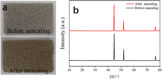
Fig. 1 shows the process for the preparation of the dual-morphological MgCo2O4. Initially, the NF was treated in a chemical bath for 15 min to remove its oxide layers and impurities, making its surface clear. Subsequently, in the first step, the Mg–Co precursor was formed on the surface of the NF via the hydrothermal method (step 1). In the second step, the MgCo2O4 crystal was formed in an air environment (step 2). Additionally, there was direct contract between the MgCo2O4 active material and NF, which effectively avoided the use of a conductive and binder agent as in the traditional process, consequently ensuring the utilization of the active material in the electrolyte.To gain a good understanding of the stability of the NF, its XRD pattern was analysed. Fig. 2a shows photographs of NF, which appeared silvery white before annealing, and then golden yellow after annealing. Subsequently, Fig. 2b exhibits the corresponding XRD patterns, where it can be found that the NF was not greatly different before and after annealing. Undoubtedly, the results suggest that the NF was very stable after annealing.
Fig. 3a shows the XRD pattern of DMCO, confirming its crystal structure and phase purity, where it can be seen that there are 6 main diffraction peaks corresponding to the crystalline planes of (111), (220), (311), (422), (511), and (440) according to the standard card of spinel MgCo2O4 (JCPDS No. 81-0667). Additionally, no other peaks can be observed, suggesting the high purity of the as-prepared DMCO. Meanwhile, Fig. 3b shows the unit cell of MgCo2O4, where the Mg ions occupy the tetrahedral sites and the Co ions occupy the octahedral sites.34Fig. 3c–f display the information on the surface chemical element composition and oxidation state of DMCO obtained from the in-depth XPS analysis. Specifically, five elements, i.e., Mg, Co, O, C, and F, appear in the full survey spectrum (Fig. 3c), where the element F comes from the NH4F in the solution, and the peak of C 1s at 284.8 eV (Fig. 3d) was used to calibrate all the binding energies. In addition, Mg 1s at the binding energy of 1304.4 eV and 1306.6 eV was split into two peaks, which indicates the presence of magnesium oxide.37,38 The Co 2p spectrum in Fig. 3e exhibits two strong peaks, which correspond to Co 2p3/2 and Co 2p1/2 and can be split into four peaks. The fitted peaks at binding energies of 781.6 eV and 796.9 eV are related to Co2+, while the fitted peaks at binding energies of 780. 3 eV and 795.6 eV are related to Co3+, which suggest the coexistence of Co2+ and Co3+. The O 1s spectrum is displayed in Fig. 3f, distinctly revealing two peaks at the binding energies of 530.8 eV and 529.8 eV.
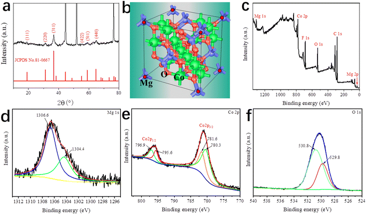 | ||
| Fig. 3 (a) XRD pattern of DMCO. (b) Unit cell of MgCo2O4. XPS (c) full survey spectrum, (d) Mg 1s, (e) Co 2p, and (f) O 1s spectra of DMCO. | ||
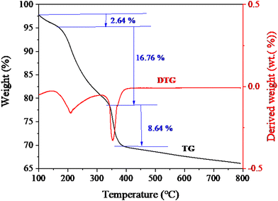
To investigate the thermal stability and components of the as-prepared material, thermogravimetric (TG) and derivative TG (DTG) measurements were further performed. Fig. 4 shows the TG and DTG curves of DMCO. The test was carried out from room temperature to 800 °C at a heating ramp of 10 °C min−1. As depicted in Fig. 4, DMCO has a weight loss process with three steps. The first step of weight loss (2.64%) below 200 °C is due to the dehydration (the absorbed water and crystalline water) of the material.5 The second and third weight loss steps (16.76% and 8.64%) below 387 °C are due to the decomposition of the metal salt.5 Additionally, distinct peaks appeared at about 208 °C and 350 °C. Meanwhile, no apparent peaks were observed above 350 °C, indicating that material structure was formed and no additional phases existed. Thus, the above-mentioned results prove that DMCO with high purity was synthesized.
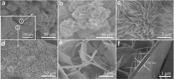
The surface morphologies of DMCO were observed by SEM for its physical characterization (Fig. 5a–f). The low- magnification SEM image in the inset of Fig. 5a shows that DMCO possesses the feature of dual morphology (marked as “①” and “②”). According to Fig. 5a (corresponding to “①”), there are plentiful urchin-like MgCo2O4 whose shapes show a uniform distribution and excellent morphology features. According to the side-magnification SEM image in Fig. 5b, their diameters are about 11 μm. Fig. 5c suggests that the urchin-like MgCo2O4 is made up of substantial thin and dense nanowires, which possess the characteristics of different angles and sufficient interval space between nanowires, where a great number of OH− ions can be filtered and electrons transported for redox reactions according to their overall angle. As shown in Fig. 5d (corresponding to “②”), numerous MgCo2O4 sheets are densely interwoven to a honeycomb-like structure on the NF, by which numerous pores can be formed, which can fully contact with OH−, greatly favoring an improvement in electrochemical performance. Fig. 5e shows that the honeycomb-like MgCo2O4 is composed of sheets on which a small quantity of needle-like MgCo2O4 grew. Meanwhile, the abundant space between the sheets, which allow the entry of large OH− ions, increases the access for their surface to contact the alkaline solution when used as an electrode. The high-magnification SEM image in Fig. 5f obviously shows that the thickness of a sheet is about 325 nm. According to SEM, the characteristics of urchin and sheet structures were observed on the electrode, which can be considered a unique morphology, and therefore the value of the electrode is obvious in the electrolyte.
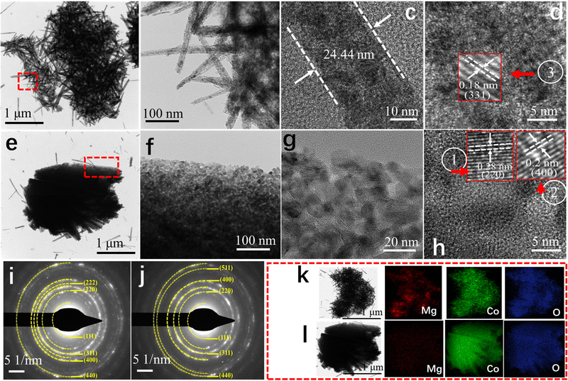
To further explore the microstructure of the as-fabricated DMCO, TEM and high-resolution TEM (HRTEM) were also performed, as important methods for observation. As depicted in Fig. 6a, it can be found that several urchins are interconnected. The TEM image shows that the urchins are comprised of disorderly nanowires interwoven with each other, which is well consistent with Fig. 6e. Furthermore, abundant mesopores were observed on their surface, fully facilitating the transport of ions in the electrolyte. The area marked with a red dotted line in Fig. 6a is enlarged in Fig. 6b, which shows that the nanowires with ultrastructural feature are composed of numerous MgCo2O4 nanoparticles, and Fig. 6c depicts that the thickness of a nanowire is around 24.44 nm. As shown in Fig. 6d, the HRTEM image exhibits that the interplanar distance of about 0.18 nm can be indexed well to the (331) crystalline planes of MgCo2O4. As shown in Fig. 6e, a single MgCo2O4 sheet can be clearly observed and the area with a blue dotted line suggests that needle-like MgCo2O4 grew on the edge of it, which is consistent with Fig. 5e and f. Fig. 6f is a magnified view of the area with a red dotted line in Fig. 6e, and coupled with Fig. 6g, it can seen that the sheet is also comprised of MgCo2O4 nanoparticles and possesses several mesopores. This microstructure can absorb substantial OH− ions in alkaline solution to improve the electrochemical performance. The HRTEM image in Fig. 6h shows the interlayer spacings of 0.20 and 0.28 nm, which are assigned to the (400) and (220) planes of spinel MgCo2O4. To get in-depth information of the material structure, selected-area electron diffraction (SAED) characterization was performed. As exhibited in Fig. 6i and j, the diffraction rings are very clear, which suggests that DMCO possesses high crystallinity.34 In addition, though calculation, there are six crystalline planes from the urchin (Fig. 6i) and sheet (Fig. 6j), corresponding to spinel MgCo2O4. Thus, the results from the HRTEM and SAED analyses agree well with the XRD results. Fig. 6k and l display the element mapping images of the urchin and sheet, respectively, where the Mg, Co, and O elements show uniform distribution on their surface. Based on this, DMCO has the merits of ultrathin structure and mesopores.
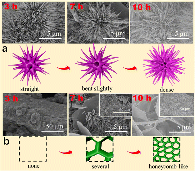
To determine the growth mechanism of DMCO in this work, as shown in Fig. 7a and b, different reaction times were used to observe their surface morphologies. As shown in Fig. 7a, the urchin-like MgCo2O4 composed of straight and thin nanowires looked undamaged when the reaction time was up to 3 h. Upon close observation, it was apparently found that nanowires varied from straight to bent slightly at 7 h and the urchin-like MgCo2O4 was made up of numerous dense nanowires with a round feature with the reaction reaching 10 h. In the case of the honeycomb-like MgCo2O4, it can be seen it was not formed when the reaction time was 3 h, as shown in Fig. 7b. Interestingly, several sheets began to connect with each other (the inset) with a smooth surface and edge, as shown in the enlarged SEM image, at 7 h. Subsequently, the MgCo2O4 sheets became greatly interpretated to form a honeycomb-like structure (the inset) and the sheets had a smooth surface and edge with needle-like MgCo2O4 at 10 h, as shown in the enlarged SEM image. Based on the results, it can be seen that the urchin-like MgCo2O4 has the growth process of “straight → bent slightly → dense”, and the honeycomb-like MgCo2O4 possesses that of “none → several → honeycomb-like”. Meanwhile, Fig. 7 also illustrate the growth mechanism.
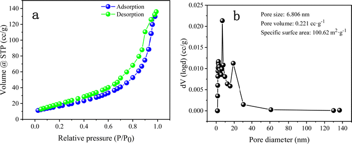
The BET test plays an indispensable role in analysing the microstructure of materials. Fig. 8 shows the N2 sorption isotherm and pore size distribution of DMCO. It is obvious that there are hysteresis loops in Fig. 8a ranging from 0.2 to 1.0 P/P0 and the specific surface area of DMCO in the Fig. 8b exhibits a superior result of 100.62 m2 g−1, which shows that the urchin-like MgCo2O4 and honeycomb-like MgCo2O4 have a significant contribution to the outstanding specific surface area and is superior to that of 63.832 and 65.25 m2 g−1 reported in the literature.36 Generally, a larger specific surface area indicates that the electrode exposes large accessible electrochemically active sites, where the chemical redox reaction occurrs.36 With an increase in the number of electrochemical reaction sites, the chemical effect of the reversible redox reaction enhanced between the electrolyte and active materials on the electrode surface. Meanwhile, a large specific surface area can also improve the electrochemical performance by accelerating the insertion and extraction of ions in the electrolyte.36 The pore size distributions are shown in Fig. 8b. The pore size of DMCO is 6.806 nm, which belongs to the range of mesopores (2–50 nm) and the pore volume of DMCO is 0.221 cc g−1, which far exceeds that of the NiCo2O4@MnMoO4 composite (0.1372 cc g−1).36 Therefore, the large specific surface area, substantial mesopores and suitable pore size to absorb large ions are obviously beneficial for enhancing the specific capacitance of the material.
3.2. Electrochemical performance of DMCO
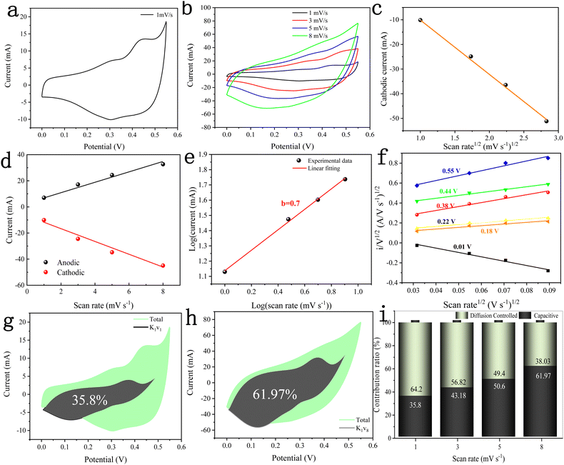
The electrochemical performance of the DMCO electrode material was investigated in 2 M KOH using the standard three-electrode system, including CV, GCD, EIS and cycle performance. Fig. 9a–i show the information from the CV curves of the DMCO electrode, which is an extremely efficient method to observe the electrochemical behavior of the material in the electrolyte. Fig. 9a shows the CV curve of the DMCO electrode at a scan rate of 1 mV s−1 in the potential range of 0 to 0.55 V. It can obviously be found that the sharp of CV curve exhibits an irregular rectangular, which means a typical pseudocapacitive characteristic. The redox peak observed in the range of 0–0.55 V originates from the faradaic redox reactions related to M–O/M–O–O–H with the alkaline electrolyte,39 where M represents Mg or Co ions. The CV curves at different scan rates of 1, 3, 5, and 8 mV s−1 are presented in Fig. 9b, where the redox peaks of all the CV curves are distinct. Furthermore, the pair of redox peaks gradually shifts towards the positive potential and negative potential with an increase in the scan rate, leading an increase in the peak currents. This is due to the ohmic resistance and polarization effect in the electrode.32 Meanwhile, Fig. 9c shows the square root of the scan rate vs. cathodic peak current curve, directly reflecting their linear relationship, which suggests that DMCO shows battery-type behavior in KOH solution.40Fig. 9d shows the linear relationship between the anodic and cathodic current and scan rate at 0.3 V from the CV test, which suggests that DMCO possesses excellent conductivity.41 To represent the electrochemical behavior of the DMCO electrode as a specific value, eqn (5) was employed, as follows:| i = avb | (5) |
log![[thin space (1/6-em)]](https://www.rsc.org/images/entities/char_2009.gif) i = b i = b![[thin space (1/6-em)]](https://www.rsc.org/images/entities/char_2009.gif) log log![[thin space (1/6-em)]](https://www.rsc.org/images/entities/char_2009.gif) v + log v + log![[thin space (1/6-em)]](https://www.rsc.org/images/entities/char_2009.gif) a a | (6) |
To further explore the pseudocapacitive behavior of the DMCO electrode, the CV curves in Fig. 9b were considered. The CV curve usually includes two types of energy storage modes,43 namely a faradaic process (also called faradaic contribution) arising from redox reactions, and a non-faradaic process (also called non-faradaic contribution) from the electric double layer. The so-called faradaic contribution includes a diffusion-controlled OH− insertion process and a redox pseudocapacitive process occurring at the surface atoms, even possibly, with atoms located in the interlayer lattice planes of the active materials.44 Besides, the non-faradaic contribution comes from double-layer capacitance.44 According to the research by Dunn and co-workers, the contribution from surface pseudocapacitance and double-layer capacitance (capacitive contribution, marked as “cap”), as well as diffusion-controlled OH− insertion contribution (diffusion-controlled contribution, marked as “diff”) can be calculated using the CV curves in Fig. 9b according to the following equation:
| i(V) = icap + idiff = k1v + k2v0.5 | (7) |
| i(V)/v0.5 = k1v0.5 + k2 | (8) |
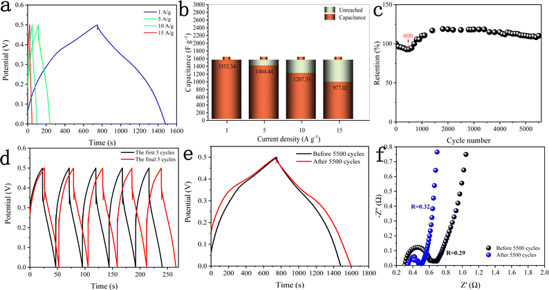
Fig. 10a shows the GCD curves of the DMCO electrode measured at different current densities in the potential window of 0 and 0.5 V, where it can be seen that the charging time of all the GCD curves is basically equal to the discharge time, showing that it exhibits high coulomb efficiency.45 Besides, all the curves are symmetric, demonstrating its good electrochemical reversibility. The specific capacitance (Cs) of the DMCO electrode was calculated using eqn (1). As shown in Fig. 10b, the DMCO electrode exhibited a specific capacitance of 1552.34, 1404.44, 1207.31, and 977.02 F g−1 at the current density of 1, 5, 10, and 15 A g−1, respectively. This notable change is because the smaller current density, the slower the contact between the DMCO active material and OH−, and thus the higher utilization of the DMCO active material.46 Cycle stability is a vital measurement for electrode materials used for supercapacitors. Thus, as revealed in Fig. 10c, it can be seen that the capacitance increased at the beginning of the 600th cycle and the cycling test was performed at a current density of 15 A g−1 for 5500 cycles. Consequently, it retained 110% of its initial specific capacitance, which indicates its remarkable electrochemical stability. Moreover, Fig. 10d and e show a comparison of the curves between the first and final 5 cycles, as well as at 1 A g−1, where it can be directly seen that they greatly differ, revealing that DMCO has great long-life cyclic stability. To evaluate the internal resistance and diffusion effect of the DMCO electrode, EIS in the frequency range of 0.001–100 kHz for before and after 5500 cycles was performed. The EIS curve is composed of a semicircle in the high frequency region and a straight line in the low frequency region. The diameter of the semicircle is controlled by electrochemical polarization, characterizing the faradaic reactions,47 which corresponds to the charge contact, i.e., the transfer resistance (Rct) between the electrode material and the electrolyte. Specifically, the bigger the semicircle, the larger resistance. The linear slope of a straight line is controlled by physical diffusion, corresponding to the resistance of electrolyte migration in the electrode material (the Warburg resistance), where the larger the linear slope, the smaller the impedance, which is inversely proportional. Besides, the intersection formed by the EIS curve and the real axis Z′ reflects the internal resistance (Rs) of the electrode, representing the sum of the ionic resistance of the electrolyte, the intrinsic resistance of the active material and the contact resistance at interface between active material and collector.47Fig. 10f presents the EIS curves of DMCO, showing a straight line in the low frequency region, and the inset illustrates a semicircle in the high frequency region, from which DMCO electrode exhibits a low Rs of 0.29 and 0.32 Ω before and after 5500 cycles, respectively. In the low frequency region, the two straight lines are parallel to the imaginary axis Z′′, revealing the excellent diffusion effect and the capacitive behavior of the electrode.48 The value of Rct is related to the diameter of the semicircle. For the high frequency region, it can obviously be seen that the diameter after 5500 cycles is smaller than that before, suggesting that the DMCO electrode possesses a relatively low resistance after long-term cycling. Furthermore, the electrochemical performance of DMCO prepared in this work is much more remarkable than that of some relevant reports in the literature, the detailed data of which is presented in Table 1. The detailed data comparison in Table 1 fully shows that the as-fabricated DMCO possesses the feature of excellent electrochemical stability, making it suitable for application in pseudosupercapacitors. Thus, the discussion above suggests that DMCO possesses the characteristic of low resistance and high specific capacitance.
| Material | Q | Stability | Potential (V) | Ref. |
|---|---|---|---|---|
| Double-urchin like MgCo2O4 | 508 F g−1@2 A g−1 | 95.9%@2000 cycles | 0.5 | 1 |
| MgCo2O4@ppy | 1079.6 F g−1@1 A g−1 | 97.4%@1000 cycles | 0.45 | 5 |
| MgCo2O4@MnO2 | 968.98 F g−1@1 mA cm−2 | 91.45%@5000 cycles | 0.5 | 29 |
| MgCo2O4@MnO2 | 887.3 F g−1@1 A g−1 | 86.0%@3000 cycles | 0.4 | 30 |
| MgCo2O4 twinned hemispheres | 626.5 F g−1@1 A g−1 | 68.9%@5000 cycles | 0.45 | 31 |
| Flower-like MgCo2O4 | 749.2 F g−1@1 A g−1 | 67.8%@5000 cycles | 0.45 | 32 |
| MgCo2O4 nanoflakes | 743.1 F g−1@1 A g−1 | 94.2%@5000 cycles | 0.43 | 33 |
| MgCo2O4 nanosheet arrays | 1706 F g−1@1 mA cm−2 | 94.65%@3000 cycles | 0.5 | 34 |
| MgCo2O4 nanosheet arrays | 1721.8 F g−1@2 A g−1 | 96%@5000 cycles | 0.55 | 40 |
| MgCo2O4@NiMoO4 | 1775 F g−1@1 A g−1 | 74.7%@5000 cycles | 0.5 | 49 |
| MgCo2O4 nanosheets | 1431.2 F g−1@1 A g−1 | 97.65%@10![[thin space (1/6-em)]](https://www.rsc.org/images/entities/char_2009.gif) 000 cycles 000 cycles |
0.35 | 50 |
| MgCo2O4@CoFe | 2007 F g−1@1 A g−1 | 80.2%@5000 | 0.45 | 51 |
| MgCo2O4@NiMn | 3757.2 F g−1@1 A g−1 | 86.9%@5000 | 0.5 | 52 |
| MgCo2O4 nanoflakes | 772.7 F g−1@1 A g−1 | Not reported | 0.55 | 53 |
| MgCo2O4 nanowires | 638.5 F g−1@1 A g−1 | Not reported | 0.55 | 53 |
| MgCo2O4@NiCo | 5701.2 F g−1@1 A g−1 | 83.7%@5000 | 0.5 | 54 |
| DMCO | 1552.34 F g−1@1 A g−1 | 110%@5500 cycles | 0.5 | This work |
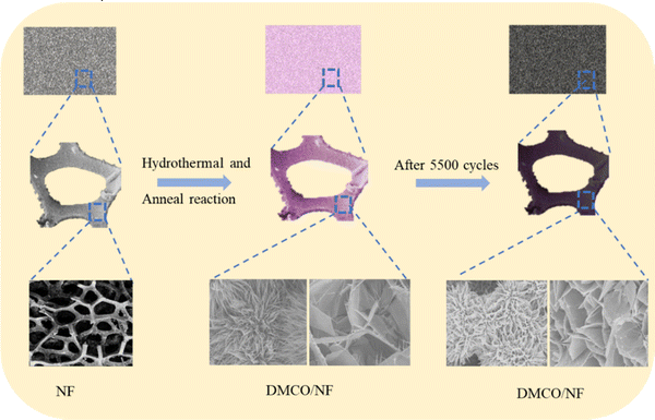
To gain a further understanding of the stability of DMCO, XRD and SEM were used to investigate its crystal structure and observe its morphologies and structure after prolonged cycling, respectively. Fig. 11a shows a photograph of NF and Fig. 11b reveals the XRD pattern before and after 5500 cycles, where it can seen that the former and the latter barely differ; meanwhile, they possess the same 6 main peaks. The results suggest that the crystal microstructure of DMCO was considerably stable after the long-term durability test. Fig. 11c and e distinctly show that the morphologies of the honeycomb-like MgCo2O4 and urchin-like MgCo2O4 remained basically flawless. Fig. 11d and f suggest that the crystal lattice of the honeycomb-like MgCo2O4 and urchin-like MgCo2O4 is the same as before, which highlights the outstanding stable performance of DMCO and agrees well with the result in Fig. 10c. Therefore, these results further prove that DMCO can be highly used as an advanced electrode material. Meanwhile, a schematic illustration of the morphological evolution of DMCO is presented in Fig. 12.
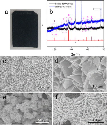 | ||
| Fig. 11 (a) Photograph of NF after 5500 cycles, (b) XRD patterns before and after 5500 cycles, and SEM images of (c) and (d) honey-comb MgCo2O4 and (c) and (f) urchin-like MgCo2O4 after 5500 cycles. | ||
3.2. Electrochemical performance of DMCO//AC ASC
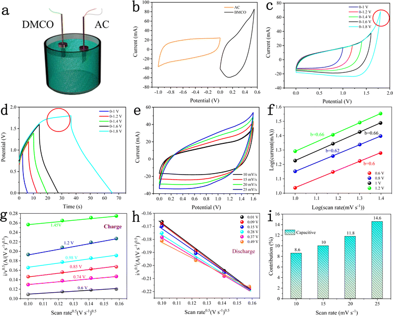
To test the practical value and application potential of the DMCO electrode, as shown in Fig. 13a, a two-electrode device was assembled with DMCO and AC as the binder-free positive and negative electrode, respectively, in the electrolyte of 2 M KOH. Fig. 13b displays the CV curves of the AC electrode (−1.0 to 0.0 V) and DMCO electrode (0.0 to 0.5 V) measured at scan rate of 10 mV s−1 in a three-electrode system. Fig. 13c shows the CV curves at various potential windows ranging from 0–1.0 V to 0–1.8 V at the scan rate of 10 mV s−1. It is obvious that the stable potential window can be extended by up to 1.6 V, which was also further confirmed by the GCD curves. When the potential window was further increased to 1.8 V, a clear sharp peak, as circled in red, was observed, which may be due to the electrolyte degradation/water splitting.55Fig. 13d presents the GCD curves varying from 0–1 V to 0–1.8 V at a current density of 5.75 mA cm−2, where the GCD curves in the potential range of 0–1.6 V are greatly symmetric, suggesting that the stable potential window can reach 1.6 V, agreeing well with the CV result. Fig. 13e illustrates the CV curves of the DMCO//AC asymmetric supercapacitor with a 1.6 V potential window at different scan rates. It can obviously be seen that the closed CV curve shows non-rectangular shape, which indicates that electric double-layer capacitance and pseudo-capacitance co-exist. As shown in Fig. 13f, the slopes of the four straight lines composed of different anodic currents are around 0.6, indicating that the reaction in the whole system is determined by diffusion and surface capacitance according to eqn (7). To get more clear information, through calculation using eqn (9), Fig. 13g and h are finally illustrated, where approximate straight lines were obtained by plotting i/v0.5vs. v0.5 at different potentials during the charge and the discharge. The capacitive contribution rate was determined based on the proportion of two areas in the CV area. Fig. 13i shows that capacitive contribution ratio increased with an increase in the scan rate.
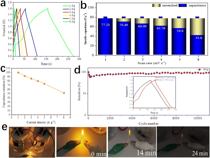
Fig. 14a depicts the GCD curves of the DMCO//AC ASC at various current densities in the potential window from 0 to 1.6 V. The specific capacitance was calculated according to eqn (1). As presented in Fig. 14b, the DMCO//AC ASC exhibited the capacitance of 77.23, 70.49, 66.09, 61.76, 56.6 F g−1 and 41.6 F g−1 at a current density of 1, 2, 3, 4, 5 A g−1 and 8 A g−1, respectively. Besides, the ASC showed 51.8% of its initial specific capacitance at a current density of 8 A g−1, as shown in Fig. 14c, demonstrating that the DMCO//AC ASC can be safely used at a large current density of 8 A g−1.36 When the current density was 8 A g−1, as shown in Fig. 14d, the DMCO//AC ASC maintained about 98.8% of its initial capacitance after 11![[thin space (1/6-em)]](https://www.rsc.org/images/entities/char_2009.gif) 000 cycles, suggesting its remarkable cycle stability. The inset displays the GCD curves before and after 11
000 cycles, suggesting its remarkable cycle stability. The inset displays the GCD curves before and after 11![[thin space (1/6-em)]](https://www.rsc.org/images/entities/char_2009.gif) 000 cycles, where they are similar, which is in agreement with Fig. 14d. Based on eqn (3), (4), and (5), the DMCO//AC ASC has a maximum energy density of 27.46 W h kg−1 at a power density of 825.9 W kg−1, and even a maximum power density of 10
000 cycles, where they are similar, which is in agreement with Fig. 14d. Based on eqn (3), (4), and (5), the DMCO//AC ASC has a maximum energy density of 27.46 W h kg−1 at a power density of 825.9 W kg−1, and even a maximum power density of 10![[thin space (1/6-em)]](https://www.rsc.org/images/entities/char_2009.gif) 240 W kg−1 at a power density of 14.79 W h kg−1. Besides, the maximum energy density of the DMCO//AC ASC shows its excellent electrochemical property according to Table 2. It is worthwhile to notice that the cycle stability of the DMCO//AC ASC is much more outstanding compared with other ASCs, as shown in Table 3. Consequently, these results demonstrate that the DMCO//AC ASC can be favorable for energy storage and possesses great potential for practical application. Fig. 14e shows the application of two tandem DMCO//AC ASCs effortlessly lighting a yellow light-emitting diode (LED) for 24 min and the variation in brightness at different times, undoubtedly indicating that the large specific surface of DMCO contributes to this result, apparently revealing its great commercial value for practical use.
240 W kg−1 at a power density of 14.79 W h kg−1. Besides, the maximum energy density of the DMCO//AC ASC shows its excellent electrochemical property according to Table 2. It is worthwhile to notice that the cycle stability of the DMCO//AC ASC is much more outstanding compared with other ASCs, as shown in Table 3. Consequently, these results demonstrate that the DMCO//AC ASC can be favorable for energy storage and possesses great potential for practical application. Fig. 14e shows the application of two tandem DMCO//AC ASCs effortlessly lighting a yellow light-emitting diode (LED) for 24 min and the variation in brightness at different times, undoubtedly indicating that the large specific surface of DMCO contributes to this result, apparently revealing its great commercial value for practical use.
| ASC | Maximum energy density | Power density | Ref. |
|---|---|---|---|
| Remark: AG denotes as activated graphene. | |||
| MgCo2O4 @MnO2//AC | 26.44 | 289.9 | 29 |
| ZnCo2O4@NiMoO4//AC | 25.3 | 787.9 | 35 |
| MgCo2O4//AC | 12.99 | 448.7 | 40 |
| NiCoSe2//AC | 24 | 800 | 56 |
| CuCo2O4@Co(OH)2//AG | 19.2 | 350 | 57 |
| MnO2@NiCo2O4/AC | 26.6 | 800 | 58 |
| CoSe2@NiSe2//AC | 20.4 | 798 | 59 |
| NiSe2@CNT//AC | 25.61 | 810 | 60 |
| NiCo2O4@MnMoO4//AC | 15 | 336 | 61 |
| DMCO//AC | 27.46 | 825.9 | This work |
Fig. 15 shows a schematic illustration of the electrochemical mechanism of DMCO, where Fig. 15a and b exhibit honeycomb-like and urchin-like MgCo2O4, respectively. In Fig. 15a, the numerous interval spaces are irregularly formed by the edge of sheets connected with each other, while the 3D structural urchins in Fig. 15b will be in total contact with OH−. On one hand, these two unique features can effectively “filter” OH−, which is conducive to increasing the contact area between the electrode material and OH−, providing more redox active sites. On the other hand, it can shorten the OH− diffusion distance, greatly reducing the Ohm resistance of the electrode. Therefore, a fast and highly reversible Faraday redox storage charge process can occur.
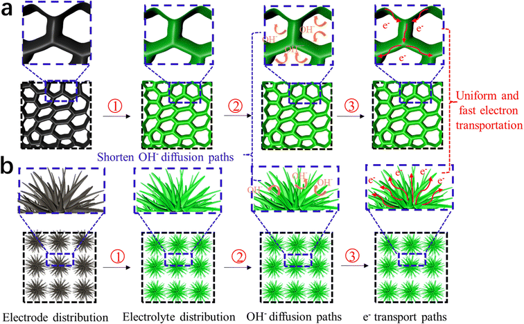 | ||
| Fig. 15 Schematic illustration of the performance mechanism of DMCO. (a) Honeycomb-like MgCo2O4 and (b) urchin-like MgCo2O4. | ||
4. Conclusions
In summary, to improve the specific capacitance and structural stability of the active materials used for supercapacitors, we designed and successfully synthesized a dual-morphological MgCo2O4 electrode material grown on NF via hydrothermal reaction at 120 °C. The as-prepared dual-morphological electrode material under SEM observation included urchin-like MgCo2O4 and honeycomb-like MgCo2O4. It showed a large specific surface area of 100 m2 g−1 and possessed abundant pores and interval spaces, fully allowing it to exhibit a superior specific capacitance of 1552.34 F g−1 at a current density of 1 A g−1 and low resistance, as well as first-class cycle stability of 110% retention when used as a binder-free electrode for a pseudocapacitor after 5500 cycles in 2 M KOH. These remarkable results suggest that the as-prepared electrode material can offer available paths, which are favorable for electrolyte penetration and transportation. Furthermore, the DMCO//AC ASC based on DMCO as the positive and AC as the negative electrode also had a high specific capacitance of 77.23 F g−1 under the condition of 1 A g−1 with a potential range of 1.6 V. Meanwhile, this ASC displayed a maximum energy density of 27.46 W h kg−1 at a power density of 825.9 W kg−1, and even an energy density of 14.79 W h kg−1 at the power density of 10240 W kg−1. Additionally, it maintained 98.8% of its original capacitance after 11![[thin space (1/6-em)]](https://www.rsc.org/images/entities/char_2009.gif) 000 cycles, showing great potential for stable electrochemical performance. Therefore, we firmly believe that MgCo2O4 is an extremely promising electrode material with considerable value for market application in supercapacitors.
000 cycles, showing great potential for stable electrochemical performance. Therefore, we firmly believe that MgCo2O4 is an extremely promising electrode material with considerable value for market application in supercapacitors.
Conflicts of interest
There are no conflicts to declare.Acknowledgements
This work was supported by Jianghan University school-level Program (2021yb021).References
- J. S. Xu, L. Wang, J. Zhang, J. H. Qian, J. Liu, Z. Q. Zhang, H. D. Zhang and X. Y. Liu, Fabrication of porous double-urchin-like MgCo2O4 hierarchical architectures for high-rate super-capacitor, J. Alloys Compd., 2016, 688, 933–938 CrossRef CAS.
- J. Zhou, Y. Huang, X. Cao, B. Ouyang, W. P. Sun, C. L. Tan, Y. Zhang, Q. L. Ma, S. Q. Liang, Q. Y. Yan and H. Zhang, Two-dimensional NiCo2O4 nanosheet-coated three-dimensional graphene networks for high-rate, long-cycle life supercapacitors, Nanoscale, 2015, 7, 7035–7039 RSC.
- R. Wang, X. Xue, W. Lu, H. W. Liu, C. Lai, K. Xi, Y. K. Che, J. Q. Liu, S. J. Guo and D. J. Yang, Tuning and understanding the phase interface of TiO2 nanoparticles for more efficient lithum ion storage, Nanoscale, 2015, 7, 12833–12838 RSC.
- A. Laleh and A. Majid, Engineering hierarchical ultrathin CuCo2O4 nanosheets array on Ni foam by rapid electrodeposition meyhod toward high-performance binder-free supercapacitors, Appl. Surf. Sci., 2018, 445, 272–280 CrossRef.
- H. W. Gao, X. H. Wang, G. H. Wang, C. Hao, S. S. Zhou and C. X. Huang, Urchin-like MgCo2O4@ppy core-shell composite grown on ni foam for a high-performance all-solid-state asymmetric supercapacitor, Nanoscale, 2018, 10, 10190–10202 RSC.
- S. K. Kaverlavani, S. E. Moosavifard and A. Bakouei, Designing graphene-wrapped nanoporous CuCo2O4 hollow spheres electrodes for high performance asymmetric supercapacitors, J. Mater. Chem. A, 2017, 5, 14301–14309 RSC.
- C. Chen, S. Wang, X. Luo, W. J. Gao, G. J. Huang, Y. Zeng and Z. H. Zhu, Reduced ZnCo2O4@NiMoO4·H2O heterostructure electrodes with modulating oxygrn vacancies for enhanced aqueous asymmetric, J. Power Sources, 2019, 409, 112–122 CrossRef CAS.
- Y. Lu, L. Li, D. Chen and G. Z. Chen, Nanowires-assembled Co3O4@NiCo2O4 architectures for high performance all-solid-state asymmetric supercapacitor, J. Mater. Chem. A, 2017, 5, 24981–24988 RSC.
- S. Y. Zhao, B. Wu and Y. Gao, Synthesis and characterization of NiCo2O4 and its super capacitor properties, Chem. Eng., 2016, 5, 13–15 Search PubMed.
- J. R. Millr and P. Simon, Electrochemical capacitors for energy management, Scince, 2008, 321, 651–652 CrossRef.
- Q. F. Wu, Y. H. Zhao, J. Yu, D. L. Song, R. R. Chen, Q. Liu, R. M. Li and M. Q. Fan, Controled growth of hierarchical FeCo2O4 ultrathin nanosheets and Co3O4 nanowires on nickel foam for supercapacitors, Int. J. Hydrogen Energy, 2019, 60, 31780–31789 CrossRef.
- Y. Q. Qiao, Q. J. Sun, O. Sha, X. Y. Zhang, Y. F. Tang, T. D. Shen, L. X. Kong and W. M. Gao, Synthesis of Mn3O4 nano-materials via CTAB/SDS vesicle templating for high performance supercapacitors, Mater. Lett., 2017, 210, 128–132 CrossRef.
- T. F. Huang, C. H. Zhao, R. J. Zheng, Y. Zhao and Z. B. Hu, Facilely synthesized porous ZnCo2O4 rodlike nanostructure for high-rate supercapacitors, Ionics, 2015, 21, 3109–3115 CrossRef CAS.
- S. B. Wang, J. Pu, Y. Tong, Y. Y. Chen, Y. Gao and Z. H. Wang, ZnCo2O4 nanowire arrays grown on nickel foam for high-performance pseudocapacitors, J. Mater. Chem. A, 2014, 2, 5434–5440 RSC.
- H. Y. Chen, J. P. Wang, X. R. Han, F. Liao, Y. F. Zhang, L. Gao and C. J. Xu, Facile synthesis of mesoporous ZnCo2O4 hierarchical microspheres and their excellent supercapacitor performance, Ceram. Int., 2019, 45, 8577–8584 CrossRef CAS.
- L. X. Zheng, Y. J. Zhao, P. H. Xu, Y. L. Pan, P. J. Yang, H. E. Wang, N. Li, Y. W. Shi and H. J. Zheng, Copper doped CoSx@Co(OH)2 hierarchical mesoporous nanosheet arrays as binder-free electrodes for superior supercapacitors, J. Alloys Compd., 2022, 911, 165115 CrossRef CAS.
- J. Ren, M. Shen, Z. L. Li, C. M. Yang, Y. Liang, H. E. Wang, J. H. Li, N. Li and D. Qian, Towards high-performance all-solid-state asymmetric supercapacitors: A hierarchical doughnut-like Ni3S2@ppy core-shell heterostructure on nickel foam electrode and density functional theory calculations, J. Power Sources, 2021, 501, 230003 CrossRef CAS.
- C. X. Miao, C. L. Zhao, H. E. Wang, K. Zhu, K. Ye, Q. Wang, J. Yan, D. X. Cao, N. Li and G. L. Wang, Hollow Co-Mo-Se nanosheet arrays derived from metal-organic framework for high-performance supercapacitors, J. Power Sources, 2021, 490, 229532 CrossRef CAS.
- P. Wang, X. Ding, R. Zhe, T. Zhu, C. Qing, Y. Liu and H. E. Wang, Synchronous defect and interface engineering of NiMoO4 nanowire arrays for high-performance supercapacitors, Nanomater, 2022, 7, 1094 CrossRef PubMed.
- G. B. Pour, L. F. Aval and M. Mirzaee, CNTs supercapacitor based on the PVDF/PVA gel electrolytes, Recent Pat. Nanotechnol., 2020, 2, 163–170 CrossRef.
- C. J. Zhang, H. Li, A. M. Huang, Q. Zhang, K. Rui, H. J. Lin, G. Z. Sun, J. X. Zhu, H. S. Peng and W. Huang, Rational design of a flexible CNTs@PDMS film patterned by bioinspired templates as a strain sensor and supercapacitor, Small, 2019, 18, 1805493 CrossRef PubMed.
- S. Q. Lin, J. Tang, K. Zhang, T. S. Suzuki, Q. S. Wei, M. K. Mukaida, Y. C. Zhang, H. Mamiya, X. L. Yu and L. C. Qin, High-rate supercapacitor using magnetically aligned graphene, J. Power Sources, 2021, 482, 228995 CrossRef CAS.
- Y. Kumar, S. Chopra, A. Gupta, Y. Kumar, S. J. Uke and S. P. Mardikar, Low temperature synthesis of MnO2 nanostructures for supercapacitor application, Mater. Sci. Energy Technol., 2020, 3, 556–574 Search PubMed.
- F. Raza, X. P. Ni, J. Q. Wang, S. F. Liu, Z. Jiang, C. L. Liu, H. F. Chen, A. Farooq and A. Ju, Ultrathin honeycomb-like MnO2 on hollow carbon nanofiber networks as binder-free electrode for flexible symmetric all-solid-state supercapacitors, J. Energy Storage Convers., 2020, 30, 101467 CrossRef.
- S. G. Krishnan, M. V. Reddy, M. Harilal, B. Vidyadharan, I. I. Misnon, M. Hasbi, A. Rahim, J. Ismail and R. Jose, Characterization of MgCo2O4 as an electrode for high performance supercapacitor, Electrochim., 2015, 161, 312–321 CrossRef CAS.
- V. Venkatachalam, A. Alsalme, A. Alswieleh and R. Jayavel, Double hydroxide mediated synthesis of nanostructured ZnCo2O4 as high performance electrode material for supercapacitor applications, Chem. Eng. J., 2017, 321, 474–483 CrossRef CAS.
- S. M. Chen, S. Q. Cui, S. Chandrasekaran, C. Ke, Z. F. Li, P. H. Chen, C. H. Zhang and Y. D. Jiang, Growth of CuCo2O4@MnMoO4 core/shell nanosheet arrays for high energy density asymmetric supercapacitors, Electrochim., 2020, 341, 135893 CrossRef CAS.
- F. G. Ji, X. X. Pan, J. H. Qin, X. M. Chen and Q. B. Zha, Facile Synthesis of NiMoO4 Nanorod Electrode for Aqueous Hybrid Supercapacitor with High Energy Density, J. Electron. Mater., 2020, 49, 4010–4017 CrossRef CAS.
- Y. F. Teng, D. Y. Yu, Y. D. Li, Y. N. Meng, Y. P. Wu, Y. Feng, Y. J. Hua, C. T. Wang, X. D. Zhao and X. Y. Liu, Facile synthesis of hierarchical MgCo2O4@MnO2 core-shell nanosheet on nickel foam as an advanced electrode for asymmetric suercapacitors, J. Electrochem. Soc., 2020, 167, 020510 CrossRef CAS.
- X. F. Guan, P. H. Luo, X. Y. Li, Y. L. Yu, Y. J. Wang, L. Zhuo and D. G. Chen, Magnesium cobaltate nanowires@magnanese dioxide nanoflakes core-Shell arrays on graphene-decorated nickel foam for high-performance supercapacitors, Int. J. Electrochem. Sci., 2018, 13, 5016–5036 CrossRef CAS.
- Y. Wang, X. Y. Ma, S. S. Li, J. L. Sun, Y. F. Zhang, H. Y. Chen and C. J. Xu, Facile solvothermal synthesis of novel MgCo2O4 twinned-hemispheres for high performance asymmetric supercapacitors, J. Alloys Compd., 2020, 818, 152905 CrossRef CAS.
- Y. Wang, J. L. Sun, S. S. Li, Y. F. Zhang, C. J. Xu and H. Y. Chen, Hydrothermal synthesis of flower-like MgCo2O4 porous microstructures as high-performance electrode material for asymmetric supercapacitor, J. Alloys Compd., 2020, 824, 153939 CrossRef CAS.
- H. Y. Chen, X. M. Du, R. Z. Wu, Y. Wang, J. L. Sun, Y. L. Zhang and C. J. Xu, facile hydrothermal synthesis of porous MgCo2O4 nanoflakes as an electrode material for high-performance asymmetric supercapacitors, Nanoscale Adv., 2020, 2, 3263–3275 RSC.
- Y. F. Teng, Y. D. Li, Z. Q. Zhang, D. Y. Yu, Y. Feng, Y. N. Meng, W. M. Meng, Y. P. Wu, X. D. Zhao and X. Y. Liu, One-step controllable synthesis of mesoporous MgCo2O4 nanosheet arrays with ethanol on nickel foam as an advanced electrode material for high performance suercapacitors, Chem. – Eur. J., 2018, 24, 14982–14988 CrossRef CAS.
- Y. N. Meng, D. Y. Yu and Y. F. Teng., Coating of the NiMoO4 nanosheets on different-morphology ZnCo2O4 nanoarrays on Ni foam and their application in battery-supercapacitor hybrid devices, J. Energy Storage Convers., 2020, 29, 101195 CrossRef.
- Y. Chen, Y. F. Li, Z. Y. Hai, Y. K. Li, S. H. Kan, J. M. Chen, X. Chen, S. Zhuiykov, D. F. Cui and C. Y. Xue, Facile-synthesized NiCo2O4@MnMoO4 with novel and functional structure for superior performance supercapacitors, Appl. Surf. Sci., 2018, 452, 413–422 CrossRef CAS.
- S. G. Krishnan, M. Harilal, I. I. Misnon, M. V. Reddy, S. Adams and R. Jose, Effect of processing parameters on the charge storage properties of MgCo2O4 electrodes, Ceram. Int., 2017, 43, 12270–12279 CrossRef CAS.
- J. S. Corneile, J. W. He and D. W. Goodman., XPS characterization of ultra-thin MgO films on a Mo (100) surface, Surf. Sci., 1994, 306, 118–124 CrossRef.
- M. Silambarasan, P. S. Ramesh, D. Geetha and V. Venkatachalam, A report on 1D MgCo2O4 with enhanced structural, morphological and electrochemical properties, J. Mater. Sci.: Mater. Electron., 2017, 28, 6880–6888 CrossRef CAS.
- S. Vijayakumar, S. Naganmuthu and K. S. Ryu, In-situ preparation of MgCo2O4 nanosheets on Ni-foam as binder-free electrode for high performance hybrid supercappacitors, Dalton Trans., 2018, 47, 6722–6728 RSC.
- Z. Chen, V. Augustyn, X. Jai, Q. F. Xiao, B. Dunn and Y. F. Lu, High-performance sodium-ion pseudocapacitors based on hierarchically porous nanowire composites, ACS Nano, 2012, 6, 4319–4327 CrossRef CAS PubMed.
- D. L. Chao, P. Liang, Z. Chen, L. Y. Bai, H. Shen, X. X. Liu, X. H. Xiao, Y. L. Zhao, S. V. Sovilov, J. Y. Lin and Z. X. Shen, Pseudocapacitive Na-ion storage boosts high-rate and areal capacity of self-branched 2D layered metal chalcogenide nanoarrays, ACS Nano, 2016, 10, 10211–10219 CrossRef CAS PubMed.
- X. H. Xia, D. L. Chao, Y. Q. Zhang, J. Y. Zhan, Y. Zhong, X. L. Wang, Y. D. Wang, Z. X. Shen, J. P. Tu and H. J. Fan, Generic synthesis of carbon nanotube branches on metal oxide arrays exhibiting stable high-rate and long-cycle sodium-ion storage, Small, 2016, 12, 3048–3058 CrossRef CAS PubMed.
- T. Brezesinski, J. Wang, S. H. Tolbert and B. Dunn, Ordered mesoporous α-MoO3 with iso-oriented nanocrystalline walls for thin-film pseudocapacitors, Nat. Mater., 2010, 9, 146–151 CrossRef CAS.
- J. S. Xu, L. Wang, Y. D. Sun, J. Zhang, C. Zhang and M. Z. Zhang, Fabrication of porous MgCo2O4 nanoneedle arrays/Ni foam as an advanced electrode material for asymmetric supercapacitors, J. Alloys Compd., 2019, 779, 100–107 CrossRef CAS.
- J. Zhang, J. P. Cheng, M. Li, L. Liu, F. Liu and X. B. Zhang, Flower-like nickel-cobalt binary hydroxides with high specific capacitance: Tuning the composition and asymmetric capacitor application, J. Electroanal. Chem., 2015, 743, 38–45 CrossRef CAS.
- L. F. Cui, L. H. Huang, M. Ji, Y. G. Wang, H. C. Shi, Y. H. Zuo and S. F. Kang, High-performance MgCo2O4 nanocone arrays grown on three-dimensional nickel foams: preparation and application as binder-free electrode for pseudo-supercapacitor, J. Power Sources, 2016, 333, 118–124 CrossRef CAS.
- V. Venkatachalam, A. Alsalme, A. Alswieleh and R. Jayavel, Double hydroxide mediated synthesis of nanostructured ZnCo2O4 as high performance electrode material for supercapacitor applications, Chem. Eng. J., 2017, 321, 474–483 CrossRef CAS.
- H. W. Gao, X. H. Wang, G. H. Wang, C. Hao, C. X. Huang and C. L. Jiang, Facile construction of a MgCo2O4@NiMoO4/NF core-shell nanocomposite for high-performance asymmetric supercapacitors, J. Mater. Chem. C, 2019, 7, 13267–13278 RSC.
- C. L. Zhao, J. K. Zhu, Y. Q. Jiang, F. Gao, L. Xie and L. Y. Chen, Facile synthesis of spinel MgCo2O4 nanosheets for high-performance asymmetric supercapacitors, Mater. Lett., 2020, 271, 127799 CrossRef CAS.
- Z. Q. Liu, Y. Liu and Y. X. Zhong, et al., Facile construction of MgCo2O4@CoFe layered double hydroxide core-shell nanocomposites on nickel foam for high-performance asymmetric supercapacitors, J. Power Sources, 2021, 484, 229288 CrossRef CAS.
- Z. Q. Liu, A. H. Li and Y. L. Qiu, et al., MgCo2O4@NiMn layered double hydroxide core-shell nanocomposites on nickel foam as superior electrode for all-solid-state asymmetric supercapacitors, J. Colloid Interface Sci., 2021, 592, 455–467 CrossRef CAS PubMed.
- R. Z. Wu, J. L. Sun and X. Y. Ma, et al., Uniform MgCo2O4 porous nanoflakes and nanowires with superior electrochemical performance for asymmetric supercapacitors, J. Alloys Compd., 2021, 884, 161087 CrossRef CAS.
- Z. Q. Liu, Y. X. Zhong and Y. L. Qiu, et al., Multilayered and hierarchical structured NiCo double hydroxide nanosheets generated on porous MgCo2O4 nanowire arrays for high performance supercapacitors, Appl. Surf. Sci., 2021, 546, 149133 CrossRef CAS.
- J. J. Fu, L. Li, J. M. Yun, D. M. Lee, B. K. Ryu and K. H. Kim, Two-dimensional titanium carbide (MXene)-wrapped sisal-like NiCo2S4 as positive electrode for high-performance hybrid pouch-type asymmetric supercapacitor, Chem. Eng. J., 2019, 375, 121939 CrossRef CAS.
- S. X. Zhou, H. L. Fan, F. He, Z. B. Fu, G. M. Gao, S. Zhang and X. Hu, Role of selenium on the pseudocapacitance of nickel-cobalt selenide, J. Energy Storage, 2022, 52, 104832 CrossRef.
- Y. Zhang, H. Liu, M. Huang, J. M. Zhang, W. Zhang, F. Dong and Y. X. Zhang, Engineering Ultrathin Co(OH)2 Nanosheets on Dandelion–like CuCo2O4 Microspheres for Binder-Free Supercapacitors, ChemElectroChem, 2017, 4, 721–727 CrossRef CAS.
- Y. Zhou, L. Ma, M. Y. Gan, M. H. Ye, X. R. Li, Y. F. Zhai, F. B. Yan and F. F. Cao, Monodisperse MnO2@NiCo2O4 core/shell nanospheres with highly opened structures as electrode materials for good-performance supercapacitors, Appl. Surf. Sci., 2018, 444, 1–9 CrossRef CAS.
- J. Y. Wang, S. Sarwar, J. Song, L. J. Du, T. B. Li, Y. D. Zhang, B. B. Li, Q. Q. Guo, J. J. Luo and X. Y. Zhang, One-step microwave synthesis of self-supported CoSe2@ NiSe2 nanoflowers on 3D nickel foam for high performance supercapacitors, J. Alloys Compd., 2022, 892, 162079 CrossRef CAS.
- Y. Y. Zheng, Y. R. Tian, S. Sarwar, J. J. Luo and X. Y. Zhang, Carbon nanotubes decorated NiSe2 nanosheets for high-performance supercapacitors, J. Power Sources, 2020, 452, 227793 CrossRef CAS.
- Y. L. Yuan, W. C. Wang, J. Yang, H. C. Tang, Z. Z. Ye, Y. J. Zeng and J. G. Lu, Three-dimensional NiCo2O4@MnMoO4 core-shell nanoarrays for high-performance asymmetric supercapacitors, ACS, 2017, 40, 10446–10454 Search PubMed.
- P. Zhang, H. He and Q. Li, Ni–Co–S nanosheets supported by CuCo2O4 nanowires for ultra-high capacitance hybrid supercapacitor electrode, Int. J. Hydrogen Energy, 2020, 45, 4784–4792 CrossRef CAS.
- M. Li, Z. Y. Meng, R. C. Feng, K. L. Zhu, F. F. Zhao, C. R. Wang, J. L. Wang and P. K. Chu, F, Fabrication of Bimetallic Oxides (MCo2O4: M = Cu, Mn) on Ordered Microchannel Electro-Conductive Plate for High-Performance Hybrid Supercapacitors, Sustainability, 2021, 17, 9896 CrossRef.
Footnote |
| † Electronic supplementary information (ESI) available. See DOI: https://doi.org/10.1039/d2ma00889k |
| This journal is © The Royal Society of Chemistry 2023 |


