 Open Access Article
Creative Commons Attribution 3.0 Unported Licence
Alignment-free construction of double emulsion droplet generation devices incorporating surface wettability contrast†
Yunus
Aslan
 ,
Olivia
McGleish
 ,
Julien
Reboud
 and
Jonathan M.
Cooper
 *
*
Division of Biomedical Engineering, University of Glasgow, Glasgow G12 8LT, UK. E-mail: jon.cooper@glasgow.ac.uk
First published on 6th October 2023
Abstract
Although polydimethylsiloxane (PDMS) is a versatile and easy-to-use material for microfluidics, its inherent hydrophobicity often necessitates specific hydrophilic treatment to fabricate microchip architectures for generating double emulsions. These additional processing steps frequently lead to increased complexity, potentially creating barriers to the wider use of promising microfluidic techniques. Here we describe an alignment-free spatial hydrophilic PDMS patterning technique to produce devices for the creation of double emulsions using combinations of PDMS and PDMS/surfactant bilayers. The technique enables us to achieve selective patterning and alignment-free bonding, producing reliable and reproducible water-in-oil-in-water W/O/W droplet emulsions. Our method involves processing devices in a vertical orientation, with the wetting transition contrast being achieved simply by imaging whilst adjusting the PDMS pouring speed (using a mobile phone, for example). We successfully obtain hydrophilic surfaces without distinguishable hydrophobic recovery using a range of surfactant concentrations. Droplet emulsions were produced with low coefficients of variation aligned with those generated with other, more complex, techniques (e.g. 3.8% and 3.1% for the inner and outer diameters, respectively). As a further example, the methods were also demonstrated for liposome production. In future we anticipate that the technique may be applied to other fields, including e.g. reagent delivery, DNA amplification, and encapsulated cell studies.
Introduction
Double emulsions, such as water-in-oil-in-water (W/O/W) and oil-in-water-in-oil (O/W/O), can be created by the microfluidic partitioning of two miscible liquids by an immiscible one.1 The presence of the immiscible liquid between inner and outer liquids enables water or oil soluble substances to be entrapped, leading to a range of diverse microfluidics applications, including reagent delivery for (bio)chemical reactions,2 artificial cell generation,3 fluorescence-activated cell sorting,4 enzyme screening,5 single cell genomic analysis,6 and real-time digital PCR/cell culture monitoring.7Double emulsion production in planar microfluidic devices, such as T-junction and flow-focusing, generally requires channels possessing opposite (hydrophobic and hydrophilic) wetting properties.8 Polydimethylsiloxane (PDMS) is the most commonly used material for such devices due to its convenience in fabrication as well as its physical and chemical properties (e.g., cheap, transparent, and with processing advantages).9 However, the hydrophobic nature of PDMS requires selective and spatial hydrophilic treatment to create appropriate fluidic arrangements.
Previously, several solutions to engineer the wettability of PDMS for double emulsion generation have been shown in either pre- or post-chip sealing layers, including those created with plasma oxidation,10–13 sol–gel deposition,14–16 layer-by-layer deposition,17 polymer coating,18,19 and surfactant use.20 For example, the selective plasma oxidation creates silanol groups altering surface properties from hydrophobic to hydrophilic.21 Oxidation is blocked by masking or covering regions of PDMS channel patterns resulting in specific regions having different wetting affinities when the full device is aligned and bonded.10 Alternatively, inlet blocking can be used to prevent plasma entering specific areas allowing blocked channels to remain hydrophobic while unblocked channels turn hydrophilic.11 The hydrophilic state of plasma treated PDMS can also be readily recovered by infusing PFDTES (1H,1H,2H,2H-perfluorodecyltriethoxysilane) while using compressed air to prevent liquid flow to undesired paths.12 Both methods are complex to implement, given the requirement for temporary gas sealing. In a similar process, but using sol–gel materials,16 fluid confinement for regional treatment can be achieved by flushing two liquids simultaneously into a channel generating a sharp affinity interface. However, these processes are linked to the fluidic design of the microchips and thus have limited flexibility. Other sol–gel coatings use photoreactive molecules to provide spatial hydrophilicity by grafting polyacrylic patches and exposing to ultraviolet (UV) light, allowing tailoring to different geometries. In these methods, molecules are attached covalently to the surface to modify the original properties, which can lead to limitations in stability.
Layer-by-layer deposition of polyelectrolytes17 can also be used for hydrophilic modification with polyallylamine hydrochloride (positively charged polyelectrolyte), NaCl (washing solution), and polysodium 4-styrenesulfonate (negatively charged) being flushed sequentially through the channel to obtain spatial wetting control.
Hydrophilic surfaces can be further obtained by deposition of the hydrophilic polymer polyvinyl alcohol (PVA).19 Flowing PVA solution into channels after plasma oxidation, with opposite airflow preventing flow in specific regions, can generate spatially selective wetting. Finally, bulk modification has been shown by embedding Pluronic surfactant into PDMS,20 with spatial modification being achieved by injecting oil or water into channel sections to maintain hydrophobicity or achieve hydrophilicity respectively.
Many of these methods require optimisation and care in fabrication. For example, plasma treatment is temporary and results in PDMS recovering its hydrophobicity,22 whilst careful spatial plasma exposure and alignment are needed as the device is irreversibly bonded once contact is made. For other methods, changes in surface chemistries are generally modified after filling sections of the device with solutions requiring the use of fluid control systems, demanding careful pressure or flow rate control. Some of these strategies contain labour intensive procedures (e.g., those using sol–gel). Furthermore, device damage may occur if coating solutions such as PVA reach undesired channel locations after plasma oxidation.
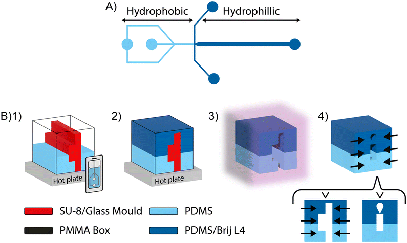
Here we present a process with minimal equipment that negates alignment issues and allows stable, spatial patterning. Our new method is based on the addition of a surfactant to tune the wettability of PDMS from bulk. We demonstrate the concept using non-ionic surfactant Brij L4 (polyoxyethylene (4) lauryl ether) to combine basic spatial wettability from a 2-layer PDMS and PDMS/Brij L4 replicate for selective hydrophilicity with an alignment-free bonding strategy, as shown in Fig. 1.
In detail, an SU-8 mould containing two flow-focusing designs Fig. 1(A), as commonly used for double emulsion formation,23 was oriented vertically and fixed at the centre of a plastic container (e.g., a hydrophobically coated PMMA box) using double-sided tape. PDMS was poured into the plastic container until the desired hydrophobic path length was achieved (for simplicity with verification using a mobile phone camera). The PDMS was then hardened on a hot plate after which the PDMS/Brij L4 mix was poured into the container filling to the mould height, completing the second layer. The mix was baked again until solid and the replicate and mould were removed with a blade, without damaging the channel structures, from the hydrophobically coated PMMA container. The top hardened joint layer was not cut, and the two layers are held together with a clip until bonded. Plasma treatment was applied to bond the layers, which can then be pressed together without requiring alignment. The device was placed in an oven overnight to achieve hydrophobic recovery of the plasma treated PDMS initial layer, creating a robust and stable device.
Experimental
Mould fabrication
Standard soft lithography with glass coverslips as a replication master was used.24 The substrate was initially immersed in acetone, methanol, and isopropyl alcohol, and subsequently dried in a stream of nitrogen gas prior to baking for 15 minutes in an oven at 120 °C. Following surface preparation, samples were spin-coated with SU-3550 photoresist (30 s at 3000 rpm) and baked on a hot plate at 95 °C for 20 minutes. The pattern on the mask was transferred into the photoresist layer by UV exposure for 75 s (MA-6, SUSS MicroTec) after which the samples were post-exposure baked, 120 °C for 5 minutes, and then soaked in Microposit developer. To achieve hydrophobicity, silanisation of the mould was performed in a vacuum desiccator. One drop of trichloro(1H,1H-2H,2H perfluorooctyl)silane (Sigma Aldrich) was deposited onto a glass slide which was placed within the desiccator with the samples for 30 minutes. A similar process is applied to the PMMA container which enabled easy release of the replicate.PDMS (Sylgard 184) was prepared by mixing base polymer using the manufacturer's ratio of 10![[thin space (1/6-em)]](https://www.rsc.org/images/entities/char_2009.gif) :
:![[thin space (1/6-em)]](https://www.rsc.org/images/entities/char_2009.gif) 1. Non-ionic Brij(R) L4 (product no.: 235989-Sigma) was blended into prepared PDMS in desired % w/w ratios. PDMS was poured into a laser cut and glued PPMA container until a vertical height equal to the hydrophilic side junctions was achieved. Following curing on a hot plate (100 °C for 2 hours), PDMS blended with Brij L4 was poured until the PMMA cuboid was filled and cured again. A Diener oxygen plasma system was used to bond the PDMS and PDMS/Brij L4 layers together (90 W for 30 s) irreversibly. No sign of leakage was observed during experiments indicating successful bonding. Fluid access holes were created using a 1 mm biopsy punch. The device was cured overnight at 80 °C to drive hydrophobic uncured PDMS chains to migrate to the surface.25 Before use the device was flushed with water (30 minutes).
1. Non-ionic Brij(R) L4 (product no.: 235989-Sigma) was blended into prepared PDMS in desired % w/w ratios. PDMS was poured into a laser cut and glued PPMA container until a vertical height equal to the hydrophilic side junctions was achieved. Following curing on a hot plate (100 °C for 2 hours), PDMS blended with Brij L4 was poured until the PMMA cuboid was filled and cured again. A Diener oxygen plasma system was used to bond the PDMS and PDMS/Brij L4 layers together (90 W for 30 s) irreversibly. No sign of leakage was observed during experiments indicating successful bonding. Fluid access holes were created using a 1 mm biopsy punch. The device was cured overnight at 80 °C to drive hydrophobic uncured PDMS chains to migrate to the surface.25 Before use the device was flushed with water (30 minutes).
The developed device had a main microfluidic channel width of 100 μm. The smallest channel in the device was 65 μm. The creation of smaller channels may prove challenging to achieve due to increased difficulty in the vertical arrangement, if the vertical height of the mould is not maintained.
Contact angle measurement
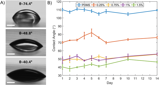
The effect of mixed surfactants (0.25, 0.75, 1, and 1.5% w/w) on the contact angle was measured using the sessile drop method.26 Measurements were made over two weeks at different locations on the surface using a drop shape analysis system (DSA100 from KRÜSS Scientific) after 30 minutes water treatment and drying in a stream of nitrogen gas, Fig. 2.Droplet and liposome generation
Hexadecane (product no.: 296317-Sigma) and Span 80 (product no.: S6760-Sigma) were used as the continuous oil phase. Inner and outer phases were DI water and DI water–glycerol–Tween 20 (product no.: G5516-Sigma and P1379-Sigma) mix respectively. Liposomes were formed using 1,2-dioleoyl-sn-glycero-3-phosphocholine (DOPC, Avanti Polar Lipids) in chloroform solution (3 mg mL−1), including 1,2-dioleoyl-sn-glycero-3-phosphoethanolamine-N-(lissamine rhodamine B sulfonyl) (Rh-PE) in a 0.1% molar ratio. Chloroform was first evaporated by a nitrogen gas stream and dried under vacuum (1 hour). The lipids were diluted in oil (and sonicated) prior to use. The liquids were transferred to the PDMS device via syringes connected to fluid pumps. Droplet videos were recorded by a Zeiss Axio.A2 microscope equipped with a Phantom V1611 high-speed camera.Results and discussion
Contact angle change
PDMS modification with surfactants has been shown to render PDMS hydrophilic.27–29 The fabrication methods using surfactants enable simple hydrophilic replicate preparation as diffusion of molecules in the polymer matrix starts only when the surface interacts with water.27 Here non-ionic Brij L4 was chosen to create hydrophilic PDMS. Serial contact angle measurements were carried out for different mixtures of PDMS and Brij L4. Fig. 2(A) illustrates the static contact angle of three concentrations (0.25%, 1%, and 1.5%) on the initial day. A distinguishable change for hydrophobic recovery was not identified over 2 weeks, Fig. 2(B). The maximum contact angle difference for the 0.25% concentration was θ ≈ 10.44°. The 1.5% concentration exhibited the lowest mean value of measured contact angle of θ ≈ 42.2°. No distinct differences between 0.75% and 1% could be seen. The maximum transmittance percentage difference was 7.3% across the visible light and near infrared range (400 to 800 nm) (Fig. S1†); greater opacity occurred for increased concentrations. Additionally, the degassing process was insufficient at higher Brij L4 concentrations since the PDMS jellified. Assuming future applications require optical transparency and minimal swelling characteristics due to surfactant addition (Fig. S3†), double emulsion formation was performed using the 0.25% Brij L4 concentration even though hydrophilicity is reduced.W/O/W generation
The W/O/W emulsions were generated using DI-water as the inner phase, hexadecane with Span80 (2% w/v) as the middle phase, and DI water/glycerol (10% v/v) with Tween-20 (2% w/v) mix as the outer phase. Droplet generation was achieved with two connected flow focusing channels. Both the inner water and the oil phase were supplied from the first junction, Fig. S2,† to form W/O droplets. The second junction was also supplied a water phase for generating W/O/W droplets. To ensure stable droplet formation, we began by forming W/O droplets initially and then converted these droplets to W/O/W by feeding the second junction inlets with water, since oil can wet the hydrophilic section of the channel regularly during emulsion formation. Fig. 3 shows a formed double droplet emulsion at the second junction, a W/O/W droplet from a W/O. The water phase was encapsulated in oil at the first junction due to the hydrophobicity of the channel. At the second junction, which was hydrophilic, the oil stream cannot wet the walls of the channel and was therefore enclosed by the outer water stream and detached. The formation times, in milliseconds, are given in each image, with a white asterisk placed left of the droplet formed. In Fig. 3, the formed water droplets are approximately 15% of the area of the pinched oil droplet emulsion.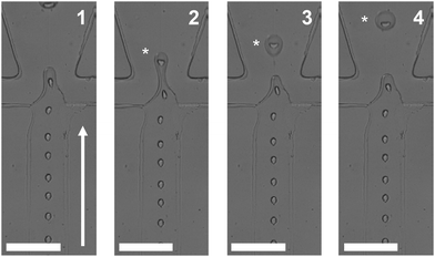 | ||
| Fig. 3 W/O/W emulsion generation. The fabricated multiple emulsion device consisted of two connected flow focusing designs (see Fig. 1(A) and S2† for full design). The oil phase was supplied from the side channels of the first junction with the water phase supplied from the middle channel. At the second junction, the water phase is supplied from the two side channels. Flow direction is depicted by the solid white arrow. A flowing W/O droplet is shown at different time intervals (the number in each image indicates the time in milliseconds, 1–4). White asterisks track a pinched W/O/W emulsion droplet. Scale bars = 100 μm. | ||
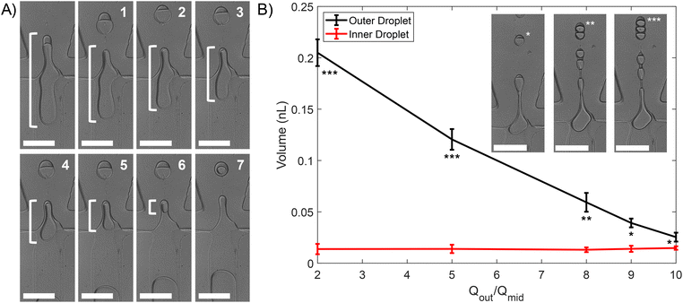
Core and outer droplet sizes can be varied by changing the flow rate.30 The inner flow rate (Qin) was varied between 0.5 μl min−1 to 5 μl min−1, the middle flow rate (Qmid) between 2.5 μl min−1 and 15 μl min−1, and the outer flow rate (Qout) between 12 μl min−1 and 80 μl min−1. In general, a low Qmid increases W/O size but reduces generation frequency at the first junction and thus encapsulation efficiency. By changing the encapsulated water volume and oil layer volume, we demonstrated control over the final size of the droplet. Fig. 4(A) shows the oil phase cannot engulf the whole water volume as it undergoes detachment (white bracket) from the outer phase allowing the remaining W/O droplet to transfer its volume into a subsequent droplet by breaking 7 times.
In addition, increasing Qmid and Qout enabled liquids to extend into the channel (forming a jet) as shown in the leftmost inset of Fig. 4(B) image of a “single” core W/O/W emulsion. The core number (e.g., single, double, and triple) was changed by varying Qout, controlling the inner/outer volume relationship. Fig. 4(B) shows that the variations in Qout impact mainly the outer volume and do not have a significant effect on the inner droplet volume, where flow rates were Qin = 2 μl min−1 and 2 μl min−1 < Qout/Qmid < 10 μl min−1. This result is consistent with a previous study.11
To determine the size variance of generated droplets, consecutive droplets were analysed, recording the mean diameters following pinching off at a distance approximately equal to 200 μm from the second junction. This was performed for two given experimental cases: one by one encapsulation in Fig. 3 and split mode encapsulation in Fig. 4(A). The size distribution of the droplets is expressed in the form of coefficient of variation (CV), 100 × σ/d, where σ is the standard deviation and d is average droplet diameter where a CV < 10% can be considered monodisperse.31,32 The histogram provided in Fig. 5(A) shows one-by-one encapsulated droplets are monodisperse (CVs were 3.8% and 3.1% for the inner and outer diameter respectively). The histogram of split mode emulsions, Fig. 5(B), exhibits polydispersity with CV ≈ 13.8% for the inner diameter and the outer diameter CV ≈ 5.6% which has a thinner oil layer. Initial polydispersity is likely to come from the extended tip of oil during initial pinching off, which has less prominence on the CV, as well as from the last splitting, since a lower water volume can only be transferred then. A significant difference between the CVs of the inner and outer diameter could have arisen from the small volume of water. A similar case can be seen in Fig. S2,† with emulsions undergoing two splits, resulting in two emulsion populations.
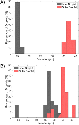 | ||
| Fig. 5 Histogram of inner and outer droplet diameters of one by one and split mode encapsulated W/O/W emulsions of Fig. 3 and 4(A). A) One-by-one encapsulated droplets are monodisperse, where CVs are 3.8% and 3.1% for the inner and outer diameter respectively, N = 25. B) Split mode emulsions, Fig. 4(A), exhibits polydispersity, CV ≈ 13.8% (inner diameter) and CV ≈ 5.6% (outer diameter), N = 25. | ||
Liposome production
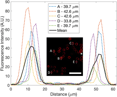
The technique can also be expanded to other multiphase systems, including liposome production. After collecting the produced emulsions, after ceasing flow, from the device in a tube and transferring a small volume to a glass slide, fluorescence imaging can be performed, Fig. 6, opening possibilities in a wide range of applications.The inset image in Fig. 6 demonstrates an example of successful emulsion transfer from the inner channels to the outlet and onto a glass slide. Across the image, emulsion droplets generally do not touch. However, two emulsion droplets do touch (indicated by the asterisk) and sustain their shape, showing that the surfactant protects against merging and thus indicates emulsion droplet stability. Fluorescence intensity across five arbitrarily chosen droplets at various locations are shown. Peaks in the graph provide the oil layer thickness while the non-fluorescing region between the peaks measures the inner diameter. CVs were 6.8% and 6.3% for the inner and outer droplets respectively (N = 25), since the droplet split number varied via flow rate arrangement.
Even though the fabrication presented is of benefit, presence of surfactants can increase the swelling characteristics of PDMS in water. Soaking the modified PDMS surfaces can lead to polymer chain rearrangement with the increase in hydrophilicity, which could lead to changes in the swelling characteristics.29 We measured the swelling characteristics of the device (see ESI†) and found no significant increase over 96 hours. However higher concentrations of the surfactant did lead to a higher percentage weight change, Fig. S3.† We note that the oligomer inside PDMS can reduce upon contact with the water phase as the surfactant can dissolve in water. In our experiments, we were able to form droplets over a period of weeks, in agreement with previous studies.20 Successful droplet formation over longer periods may depend on how long the device is exposed to water. The diffusion of surfactants into bare PDMS might also impact device performance over longer periods. We have estimated the diffusivity (see ESI†) based on contact angle changes over time and found that diffusion was slow in solidified PDMS.33–35 We further expect that any diffusion would not generate a significant initial impact on the production of droplets as the oil phase is constantly wetting the initial section of the device allowing the surface to adapt to the liquid phase properties.
Conclusion
We have shown a simple alignment-free and selective hydrophilic patterning method using surfactant added to PDMS for double emulsion generation. The processing can be performed without a fluid dispensing system. The selective patterning is achieved by casting PDMS/Brij L4 mixture on hardened PDMS within a mould. Spatial control is achieved using a mobile phone camera and the standard alignment requirement is resolved by a paperclip like hardened PDMS/Brij layer. We demonstrate that the fabrication process allows formation of several different forms of W/O/W. A similar strategy can be used for formation of O/W/O droplets if the mould or liquid pouring process is reversed. We believe this process offers an opportunity for reliable production of multiple emulsions.Author contributions
Yunus Aslan: conceptualisation, methodology, formal analysis, investigation, data curation, visualisation, writing – original draft, writing – review & editing. Olivia McGleish: methodology, formal analysis, investigation, data curation, visualisation, writing – original draft, writing – review & editing. Julien Reboud: supervision, writing – review & editing. Jonathan M. Cooper: supervision, writing – review & editing.Conflicts of interest
There are no conflicts to declare.Acknowledgements
We are grateful to Dr Fan Gao for training on fabrication techniques. This work was supported by the Republic of Turkey Ministry of National Education (MoNE-1416/YLSY) and the United Kingdom Research and Innovation Engineering and Physical Sciences Research Council (EP/P001114/1 and EP/T021020/1). All data associated with this work is available open access within the University of Glasgow's repository Enlighten at https://dx.doi.org/10.5525/gla.researchdata.1505.References
- G. T. Vladisavljević, R. Al Nuumani and S. A. Nabavi, Micromachines, 2017, 8(75) DOI:10.3390/mi8030075.
- A. Stucki, P. Jusková, N. Nuti, S. Schmitt and P. S. Dittrich, Small Methods, 2021, 5(8), 2100331, DOI:10.1002/smtd.202100331.
- C. Martino and A. J. deMello, Interface Focus, 2016, 6(4), 20160011, DOI:10.1098/rsfs.2016.0011.
- K. K. Brower, C. Carswell-Crumpton, S. Klemm, B. Cruz, G. Kim, S. G. K. Calhoun, L. Nichols and P. M. Fordyce, Lab Chip, 2020, 20(12), 2062–2074, 10.1039/d0lc00261e.
- J. Vallapurackal, A. Stucki, A. D. Liang, J. Klehr, P. S. Dittrich and T. R. Ward, Angew. Chem., Int. Ed., 2022, 61, e202207328, DOI:10.1101/2021.09.20.460989.
- T. W. Cowell, A. Dobria and H. S. Han, ACS Appl. Mater. Interfaces, 2022, 14(18), 20528–20537, DOI:10.1021/acsami.1c22692.
- W. Wu, S. Zhou, J. Hu, G. Wang, X. Ding, T. Gou, J. Sun, T. Zhang and Y. Mu, Adv. Funct. Mater., 2018, 28(39), 1803559, DOI:10.1002/adfm.201803559.
- P. Jankowski, D. Ogończyk, L. Derzsi, W. Lisowski and P. Garstecki, Microfluid. Nanofluid., 2013, 14, 597–604, DOI:10.1007/s10404-012-1078-4.
- E. Berthier, E. W. K. Young and D. Beebe, Lab Chip, 2012, 12(7), 1224–1237, 10.1039/c2lc20982a.
- S. Li, X. Gong, C. S. Mc Nally, M. Zeng, T. Gaule, C. Anduix-Canto, A. N. Kulak, L. A. Bawazer, M. J. McPherson and F. C. Meldrum, RSC Adv., 2016, 6(31), 25927–25933, 10.1039/c6ra03225g.
- S. C. Kim, D. J. Sukovich and A. R. Abate, Lab Chip, 2015, 15(15), 3163–3169, 10.1039/c5lc00626k.
- C. Feng, K. Takahashi and J. Zhu, Front. Bioeng. Biotechnol., 2022, 10, 891213, DOI:10.3389/fbioe.2022.891213.
- H. Liu, J. A. Piper and M. Li, Anal. Chem., 2021, 93(31), 10955–10965, DOI:10.1021/acs.analchem.1c01861.
- A. R. Abate, A. T. Krummel, D. Lee, M. Marquez, C. Holtze and D. A. Weitz, Lab Chip, 2008, 8(12), 2157–2160, 10.1039/b813405g.
- J. Thiele, A. R. Abate, H. C. Shum, S. Bachtler, S. Förster and D. A. Weitz, Small, 2010, 6(16), 1723–1727, DOI:10.1002/smll.201000798.
- A. R. Abate, J. Thiele, M. Weinhart and D. A. Weitz, Lab Chip, 2010, 10(14), 1774–1776, 10.1039/c004124f.
- W. A. C. Bauer, M. Fischlechner, C. Abell and W. T. S. Huck, Lab Chip, 2010, 10(14), 1814–1819, 10.1039/c004046k.
- L. Li, Z. Yan, M. Jin, X. You, S. Xie, Z. Liu, A. van den Berg, J. C. T. Eijkel and L. Shui, ACS Appl. Mater. Interfaces, 2019, 11(18), 16934–16943, DOI:10.1021/acsami.9b03160.
- T. Trantidou, Y. Elani, E. Parsons and O. Ces, Microsyst. Nanoeng., 2017, 3, 16091, DOI:10.1038/micronano.2016.91.
- A. Kamnerdsook, E. Juntasaro, N. Khemthongcharoen, M. Chanasakulniyom, W. Sripumkhai, P. Pattamang, C. Promptmas, N. Atthi and W. Jeamsaksiri, RSC Adv., 2021, 11(56), 35653–35662, 10.1039/d1ra06887c.
- S. H. Tan, N. T. Nguyen, Y. C. Chua and T. G. Kang, Biomicrofluidics, 2010, 4(3), 032204, DOI:10.1063/1.3466882.
- T. G. Oyama, K. Oyama and M. Taguchi, Lab Chip, 2020, 20(13), 2354–2363, 10.1039/d0lc00316f.
- D. T. Chong, X. S. Liu, H. J. Ma, G. Y. Huang, Y. L. Han, X. Y. Cui, J. J. Yan and F. Xu, Microfluid. Nanofluid., 2015, 19, 1071–1090, DOI:10.1007/s10404-015-1635-8.
- J. C. McDonald and G. M. Whitesides, Acc. Chem. Res., 2002, 35(7), 491–499, DOI:10.1021/ar010110q.
- M. Pascual, M. Kerdraon, Q. Rezard, M. C. Jullien and L. Champougny, Soft Matter, 2019, 15(45), 9253–9260, 10.1039/c9sm01792e.
- D. Y. Kwok and A. W. Neumann, Adv. Colloid Interface Sci., 1999, 81(3), 167–249, DOI:10.1016/S0001-8686(98)00087-6.
- E. Holczer and P. Fürjes, Microfluid. Nanofluid., 2017, 21, 81, DOI:10.1007/s10404-017-1916-5.
- M. Yao and J. Fang, J. Micromech. Microeng., 2012, 22(2), 25012, DOI:10.1088/0960-1317/22/2/025012.
- A. Fatona, Y. Chen, M. Reid, M. A. Brook and J. M. Moran-Mirabal, Lab Chip, 2015, 15(22), 4322–4330, 10.1039/c5lc00741k.
- A. Jans, J. Lölsberg, A. Omidinia-Anarkoli, R. Viermann, M. Möller, L. De Laporte, M. Wessling and A. J. C. Kuehne, Polymers, 2019, 11, 1887, DOI:10.3390/polym11111887.
- S. ten Klooster, S. Sahin and K. Schroën, Sci. Rep., 2019, 9, 7820, DOI:10.1038/s41598-019-44239-7.
- L. Nan, T. Mao and H. C. Shum, Microsyst. Nanoeng., 2023, 9, 24, DOI:10.1038/s41378-023-00502-6.
- D. J. O'Brien, A. J. Sedlack and M. Paranjape, in Proceedings of the IEEE International Conference on Micro ElectroMechanical Systems (MEMS), 2020, vol. 2020-January Search PubMed.
- D. J. O'Brien, A. J. H. Sedlack, P. Bhatia, C. J. Jensen, A. Quintana-Puebla and M. Paranjape, J. Microelectromech. Syst., 2020, 29(5), 1216–1224, DOI:10.1109/JMEMS.2020.3010087.
- T. Young, Philos. Trans. R. Soc., B, 1805, 95, 65–87, DOI:10.1098/rstl.1805.0005.
Footnote |
| † Electronic supplementary information (ESI) available: Transmittance change graph, image of double emulsion generation, PDMS and surfactant swelling graph, and diffusivity of surfactants. Video 1: one-by-one droplet encapsulation. Video 2: split droplet encapsulation. See DOI: https://doi.org/10.1039/d3lc00584d |
| This journal is © The Royal Society of Chemistry 2023 |

