 Open Access Article
Creative Commons Attribution 3.0 Unported Licence
Enabling batch and microfluidic non-thermal plasma chemistry: reactor design and testing†
P.
Roszkowska
 a,
A.
Dickenson
 b,
J. E.
Higham
c,
T. L.
Easun
 *de,
J. L.
Walsh
*bf and
A. G.
Slater
 *a
*a
aDepartment of Chemistry and Materials Innovation Factory, School of Environmental Sciences, University of Liverpool, Liverpool, UK. E-mail: anna.slater@liverpool.ac.uk
bDepartment of Electrical Engineering and Electronics, School of Environmental Sciences, University of Liverpool, Liverpool, UK
cDepartment of Geography and Planning, School of Environmental Sciences, University of Liverpool, Liverpool, UK
dSchool of Chemistry, Cardiff University, Main Building, Park Place, Cardiff CF10 3AT, UK
eSchool of Chemistry, University of Birmingham, Haworth Building, Birmingham B15 2TT, UK. E-mail: t.l.easun@bham.ac.uk
fYork Plasma Institute, School of Physics, Engineering & Technology, University of York, York YO10 5DQ, UK. E-mail: james.l.walsh@york.ac.uk
First published on 10th May 2023
Abstract
Non-thermal plasma (NTP) is a promising state of matter for carrying out chemical reactions. NTP offers high densities of reactive species, without the need for a catalyst, while operating at atmospheric pressure and remaining at moderate temperature. Despite its potential, NTP cannot be used comprehensively in reactions until the complex interactions of NTP and liquids are better understood. To achieve this, NTP reactors that can overcome challenges with solvent evaporation, enable inline data collection, and achieve high selectivity, high yield, and high throughput are required. Here, we detail the construction of i) a microfluidic reactor for chemical reactions using NTP in organic solvents and ii) a corresponding batch setup for control studies and scale-up. The use of microfluidics enables controlled generation of NTP and subsequent mixing with reaction media without loss of solvent. The construction of a low-cost custom mount enables inline optical emission spectroscopy using a fibre optic probe at points along the fluidic pathway, which is used to probe species arising from NTP interacting with solvents. We demonstrate the decomposition of methylene blue in both reactors, developing an underpinning framework for applications in NTP chemical synthesis.
Introduction
Plasma is recognised as the fourth state of matter and can be classed as either thermal or non-thermal depending on the thermal equilibrium between the electrons and the background gas particles in which it is generated.1 In non-thermal plasma (NTP) the electron temperature is much higher than that of the surrounding gas particles, which can be close to room temperature; this can be exploited to perform chemistry that is challenging to achieve using conventional methods, for example, CO2 conversion.2–5NTP can be generated by an application of a high voltage (HV) across a neutral gas. The addition of energy causes ionisation of the neutral gas molecules through collisions with charged particles resulting in the production of active species.6 Active species are the driving force for chemical changes; when generated with plasma they include electrons, ions, neutrals, and radicals as well as UV light and strong electric field(s).7 The type and concentration of active species produced from NTP is dependent on many factors, including the type of gas carrier and its flow rate, the humidity, the surrounding temperature and the electric field intensity.8–10 Many benefits can be envisaged if the flux and nature of active species could be controlled, including efficient reaction catalysis, bespoke modification of materials, sterilization of, e.g., catheters, and the discovery of new chemical transformations.11,12
Indeed, several approaches have been taken to exploit NTP. One of the most popular applications is the chemical and biological purification of water, air and surfaces.13–17 NTP has also been used for the modification and synthesis of polymers16,18,19 and metal–organic frameworks (MOFs)20–22 as well as in CO2 conversion3,23,24 and for a range of oxidation processes.12,25–28 However, several limitations such as lack of control over the plasma flux, selectivity or solvent evaporation still need to be addressed before NTP can become a mainstream synthetic technique.1,9,10,12,29
For example, to date, studies of NTP–liquid interactions have mostly been performed in water,30 which limits the scope of chemical reactions that can be studied.31 A further barrier is the difficulty of comparisons between studies: given the many parameters that affect the flux and composition of NTP, there is a need for standardization in reporting to improve reproducibility. NTP can be generated using a variety of different methods such as atmospheric pressure plasma jets (APPJ) excited with radio frequency (RF), corona discharges excited using direct current (DC), and dielectric barrier discharge (DBD) with an alternating current (AC) power supply.13,15,16,32 Each of these methods has a specifically selected type of reactor configuration (APPJ: plasma jet; corona discharge: parallel plate; DBD: pin electrode) and electrical excitation (RF, DC, AC), and the configurations in which they are used vary considerably. This flexibility does allow adjustment of the setup to the needs of a given experiment, but renders comparisons between studies challenging, thus limiting general understanding of NTP activity.33
Another common observation in plasma-driven chemistry is solvent evaporation.10,34 In a recent study that focused on initiating aqueous radical reactions with NTP, 50% evaporation of the solvent was observed.34 Significant loss of solvent changes the concentration of the solution and can hinder the diffusion of active species between plasma and liquid. The effect of concentration differences has been recorded by many studies: for example, Tao et al. studied the efficiency of a DBD reactor for Fenton catalysis, showing that the reaction concentration, amongst other parameters, was a significant factor.35
Perhaps the most critical barrier is the complexity of the interactions and species generated when NTP and solvents mix; very little is known about the lifetimes and identities of the species present. Addressing this complexity is particularly important for studying and optimising solution-phase chemical transformations. Current methods of studying interactions between plasma and liquid do not give sufficient time or spatial resolution to track and identify the complex and short-lived species involved.10,36,37
New methods of generating and measuring plasma to benefit chemical reactions are therefore needed, and microfluidic chips are the ideal platform for such studies. Microfluidics can be defined as both a) the study of the physical behaviour and control of fluids constrained in small (micro and nanometre) scales and b) technology enabling biological and chemical experiments at nano/micrometre scale.9,12,38,39 Thanks to the design of microfluidic devices more control over experimental processes is possible, such as via internal flow focusing junctions and droplet manipulation.40 Moreover, these methods provide simpler control of physical properties of reactions such as temperature, pressure, and flow rate.41
Pioneering approaches that combine microfluidic devices with plasma have been explored.4,9,12 The plasma roadmap from 2012,33 and, later, a review on microfluidic plasmas from 2021,9 highlight the benefits of these evolving methods. These studies focus on small-scale applications based on microplasma techniques, such as the exploitation of low-thermal plasma activation as a catalyst. For example, the work of Wengler et al. yielded a microfluidic device (non-thermal atmospheric pressure plasma discharges, DBD) that can oxidise cyclohexane showing the potential of good selectivity (70–80%) but low conversion (10–35%).12 A similar trend was observed in the work of Ogunyinka et al.;4 their plasma microfluidic device (also non-thermal atmospheric pressure plasma discharges, DBD) was successfully used for epoxidation of trans-stilbene. A single pass of starting reagent through the chip in presence of plasma treatment generated a conversion yield of 33% and selectivity of 50% with benzaldehyde as a by-product. They reported that by increasing treatment to multi-pass reaction the yield increased; however, a longer residence time compromised the selectivity.
As described by the studies above, non-thermal plasma chemistry, particularly in combination with microfluidics, may offer new chemistry, greater selectivity, higher efficiency, and new routes to catalytic transformations. Despite this promise, the challenges described in understanding the origin and mechanisms behind these potential advantages remain—limiting the ability of chemists to understand, optimize, and use NTP methods. Further improvement of microfluidic plasma reactors, particularly with the addition of diagnostic tools, will help to uncover the details of chemical reaction mechanisms that happen at the interface of liquid and plasma, unlocking the development and optimisation of a wide range of plasma-assisted chemical reactions. However, none of the existing NTP microfluidic studies incorporate in situ time and space-resolved analysis, particularly of NTP in contact with liquids, limiting the information that can be obtained. In some cases that do mix NTP with liquids,12,17 direct measurement at the point of NTP generation is not possible because the electrodes are situated above and below the channels; in other studies,4 direct measurement would be possible if a suitable housing was designed for an analytical probe. In order to fully benchmark and understand whether batch or microfluidic methods offer the optimal configuration for a given transformation, it is also important to construct a batch set-up that is as close as possible to the microfluidic reactor.
Thus, in this study, we designed and manufactured two complementary experimental setups to allow a better understanding of reactions on small (microfluidic) and large scale (batch) reactions (Fig. 1). The microfluidic setup in particular allows minimal solvent evaporation compared with control experiments without NTP; we demonstrated effective aqueous degradation of methylene blue (MB) dye, a common water pollutant42 frequently used as a model compound for NTP degradation studies, with minimal solvent loss. In a further step towards in situ study of the time/space evolution of the NTP/solvent interaction we also describe a simple custom-built 3D printed housing for a fibre optic probe that enables on-chip emission spectroscopy. Using that setup, we investigated interaction of NTP with organic solvents: chloroform and dichloromethane (DCM) in terms of solvent evaporation and species detectable with the OES probe. Having both platforms operating on the same principle allowed us to perform and compare experiments on different scales. We anticipate that the microfluidic system described here, which allows efficient combination of NTP and reaction media with informative in situ diagnostics, will in future be used to develop a better understanding of plasma chemistry, and thus help to drive exploration of new synthetic chemistry routes that can exploit the unique benefits of non-thermal plasma.
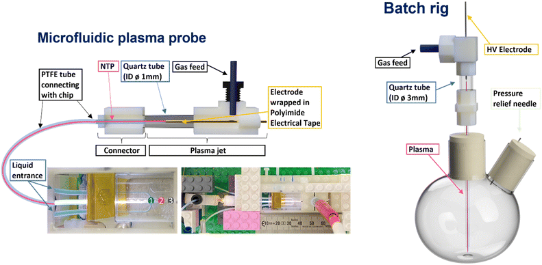 | ||
| Fig. 1 Schematic representation of microfluidic and batch NTP reactors. Numbers on the microfluidic chip indicate positions where OES was performed. | ||
Experimental
Plasma setup
Plasma generating electrodes were used for both batch and microfluidic reactors. The plasma generation approach used for the microfluidic setup (Fig. 1, left side) consisted of an HV copper wire electrode (0.15 mm diameter) shrouded by Kapton tape in the centre of a quartz tube (3 mm diameter). The plasma setup used in the batch reactor (Fig. 1, right side) consisted of a tungsten pin (1.8 mm diameter) acting as the HV electrode in the centre of a quartz tube (8 mm diameter). In both cases, the plasma forming electrode sections were connected to reactors via narrower tubing to carry the plasma/plasma generated species to the liquid interfaces. For the microfluidic system, this consisted of PTFE tubing (0.25 mm internal diameter), while quartz tubing (1 mm internal diameter) was used for the batch reactor.To generate the plasma in each reactor setup, a custom-built HV sinusoidal power source was used to drive the electrodes at 20 kHz. A CT4026 HV probe and Pearson 2877 current probe enabled the voltage/current signals to be monitored on a Keysight EDUX1052A oscilloscope, and a constant plasma discharge power of 0.5 & 5 W was maintained in the microfluidic and batch reactor setups, respectively. In both cases, argon was used as the carrier gas. An Aalborg GFC 17 mass flow controller was used to regulate the flow of argon to both reactors. Flow rates of 80 and 490 ml min−1 were used in the microfluidic and batch cases, respectively (see Table 1).
Reactor setup
The first step for the generation of non-thermal plasma microfluidic reactor (NTP-MR) was to design a microfluidic chip with a flow-focused junction using computer-aided design (CAD), then manufacture it using fused deposition modelling (FDM) 3D printing technology. The development stages with detailed pictures of the prototypes are available in supporting information, along with FDM settings used for the 3D printing and links to the STL files with designs.The first two prototypes of microfluidic chips were able to successfully generate plasma inside of the channels. The chips printed using FDM technology were suitable for initial trials, but their optical transparency was insufficient for diagnostic Optical Emission Spectra (OES) to be recorded. Consequently, the chip material was changed from polyethylene terephthalate glycol (PETg) to quartz, which is both more transparent and more chemically resistant.
A standard Dolomite microfluidic quartz chip with a flow-focused junction (Dolomite (3200130)) was ultimately chosen for the NTP-MR. A plasma electrode and connector for the standard PTFE microfluidic tubing was designed and manufactured. The latter allowed adaptation of the Dolomite kit to generate a secure and airtight connection between the chip and plasma electrode, which together created the non-thermal plasma microfluidic reactor (Fig. 1, left side). This design benefits from the use of pre-existing equipment (easy access to a range of microfluidic chips, consumables and set methods to control the flow rate of the reacting solutions) simultaneously with the plasma technology. A video of the NTP-MR in operation is available via link in the ESI.†
The final step of the completed NTP-MR was the addition of the scaffold holding a fibre optic in place to facilitate OES measurements (ESI† Fig. S4 and S5). Thanks to the moving parts of the 3D printed scaffold, the OES fibre can be moved along the channels. The OES measures the intensities of the sample emission indicating the species constituting the plasma glow. The types of species present depend on the feed gas and plasma generation method.30 Examples of species detectable by OES are hydrocarbons (CH), argon, nitrogen (NO, N2), and oxygen species (O, OH).42 The spectrum can be collected from a specific location on the chip, allowing the creation of a species map along the channels. Not all the peaks can be easily identified but monitoring the spectrum of the plasma before and after contact with reactant/solvent allows the identification of newly appearing/disappearing peaks and their origin.43,44
Alongside the NTP-MR, a batch reactor was assembled and used as a platform for control experiments. The design of the plasma electrode used in the batch reactor (Fig. 1, right side) was based on the design of the NTP-MR. The batch setup was designed to mimic the NTP-MR as much as possible to allow scale-up testing of successfully performed reactions in the NTP-MR. Additionally, it can be used as a pre-assessment for more challenging reactions that may potentially cause blockage in microfluidic channels. The batch setup does not accommodate the OES measurement but can run reaction chemistry under an inert atmosphere if needed.
Methylene blue degradation
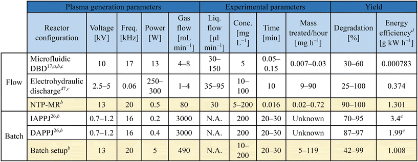
Methylene blue (MB) degradation was selected as a method to compare the batch and microfluidic set-ups. The use of NTP for MB degradation is often reported to demonstrate plasma reactivity, originating with NTP studies for water purification.7 The breakdown process of MB molecules in argon plasma is predominantly caused by OH radicals and H2O2 and is explained in detail in the literature, selected highlights presented in ESI,† Scheme S1.26,45–47 In short, H2O2 is produced which can be converted into hydroxyl radicals in the presence of UV light. Both the OH and H2O2 species are the cause of MB degradation and concomitant colour change in the solution from blue to colourless.47Table 1 shows a summary of the parameters used in our experiments (entries 3 and 6) contrasted with three selected studies for MB degradation with plasma. Each of the previously reported studies was performed using a different setup: NTP microfluidic chip (entry 1),17 a solution in an open flask treated with a) indirect and b) direct atmospheric pressure plasma jets (IAPPJ, DAPPJ, entries 4 and 5),26 and a continuous flow hydraulic discharge system (entry 2).47 All of these experimental methods were designed to focus on different parameters that could affect degradation and the results varied from system to system. It was difficult to decide which of the reported methods performs the “best”, due to differences in important parameters such as flow rate, type of feed gas, power used to initiate plasma as well as the method of plasma delivery to the MB solution.
All of the above parameters directly influence the degradation rate through the impact on density, concentration and diffusion of active species between the plasma and liquid phase. It is important to acknowledge that these factors would have a similar impact on any other chemical reaction. Consequently, having more consistency between parameters on plasma setups for plasma in contact with liquid would help to give NTP in chemistry a more accessible foundation for future research in this area.
In this study, the NTP-MR and batch rig were tested for their ability to degrade methylene blue (MB) with NTP. Four aqueous MB solutions of increasing concentration were tested: 5 mg L−1, 10 mg L−1, 50 mg L−1 and 200 mg L−1; these concentrations were chosen to compare the efficacy of our setup with previously reported studies, stated in Table 1 and explained in detail in the results and discussion section.17,26,47 Tests were divided into two sections: a) batch study and b) NTP-MR, to confirm the presence of active species in both systems. Ex situ UV-vis absorption spectroscopy of the reaction solutions was used to determine the percentage of MB degradation resulting from NTP treatment in the two systems.
In the batch tests, the MB solution was poured into a 50 ml round bottom flask along with a magnetic stirrer, sealed with rubber septa and left under a continuous flow of argon for around 3 minutes (vented via a small-bore pressure relief needle), removing any residual air from the flask. Then, plasma was supplied to the system via the quartz tube. A 0.5 ml sample was taken out at 10, 20 and 30 minutes to monitor the progress of the degradation by UV-vis absorption spectroscopy. 0.1 ml of the sample was then added to 3 ml of DI water and the absorption band of each sample was compared against the original solution. The total plasma exposure time with the batch setup was 30 minutes.
The NTP-MR reactor was connected to the plasma generation equipment and in all MB experiments, the Dolomite large droplet junction chip (3200130) was used. The liquid was delivered via two channels of the continuous phase mixed at the flow focused junction with plasma coming from the disperse phase (Fig. 1), maintaining the annular flow. Annular flow is a common flow regime for gas–liquid flow17 where the liquid phase forms a liquid film flowing on the walls of the channel and gas is flowing in a gas core. Dolomite Mitos P-pumps (3200016) were used for liquid flow control, and the flow of MB solutions was set to 30 μl min−1; argon used for generating plasma was delivered at 80 ml min−1. The residence time for plasma and methylene blue solution at annular flow was estimated to be 1 s and calculated as the ratio of the inner volume of the reactor to the volumetric flow rate (eqn (1)), the volume of the channel after the junction is 1.35 μL.39
 | (1) |
OES on-chip measurements
Two tests were performed; the first investigated differences in the spectra of the plasma glow just after the junction (at the blue spot location in Fig. 1) when it was in contact with water, DCM or chloroform. All liquids and feed gas for plasma were introduced to the chip (Dolomite (3200130)) using the same equipment as stated in previous section. The flow rate of liquids was 50 μl min−1 and of argon was 80 ml min−1, maintaining annular flow. Secondly, the plasma glow was probed along the channel in contact with water at three points: i) just after the junction, then ii) 0.3 cm and iii) 0.7 cm further from the first point. The flow rate of water was 50 μl min−1 and argon was 70 ml min−1. An Ocean Optics FLAME-S-UV-VIS spectrometer with a QP400 fibre probe was used to take the measurements and spectra were recorded using SpectraSuite. The integration time was 4 seconds, and 3 scans were averaged for each spectrum.Solvent evaporation study
The physical evaporation response of water, chloroform and DCM to flowed plasma exposure was tested in the batch and NTP-MR reactors. Water is commonly used as a solvent for plasma reactions.10,34,48 The organic solvents were chosen for our initial trials as they are not flammable but are commonly used in chemical reactions. Each solvent was poured into a 50 ml round bottom flask, sealed with rubber septa and left under a continuous flow of argon for a minute (vented via a small-bore pressure relief needle). The argon flow rate was set to 490 ml min−1 to keep the settings consistent in comparison with other experiments in this study, and temperature, evaporation, and colour changes were monitored. Additionally, control experiments were performed whereby each solvent was poured into the flask and kept under constant argon flow without plasma generation. During 30 minutes of plasma exposure to each solvent, temperature changes were recorded in 5 minutes intervals with an IR thermometer. No significant temperature fluctuations and no visible colour changes were observed in either the plasma-on or plasma-off experiments.Next, the NTP-MR was tested. The flow rate of argon (plasma feed gas) was set to 80 ml min−1, and the flow rate of DCM, chloroform and water were kept at 30 μl min−1. The solvent sample size was 4 ml in total. Similar to the batch experiment, control tests were performed to see the level of solvent evaporation in the setup without the use of plasma. Each experiment was run in triplicate.
Results and discussion
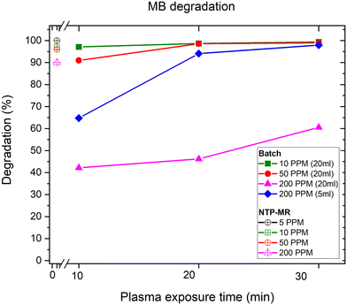
In the batch MB degradation experiment, in addition to concentration variation, the importance of the volume of sample (5 ml vs. 20 ml) was investigated at the highest concentration (200 mg L−1) (Fig. 2). We hypothesised that any significant volume-dependent variation in degradation would be most easily observed at the highest concentrations. For 20 ml samples at lower concentrations (10 mg L−1 and 50 mg L−1, green squares and red circles respectively), 10 minutes was sufficient to degrade between 90–97% of the MB reaching 99% degradation after 30 minutes. At the higher concentration of 200 mg L−1 (pink triangles), the degradation percentage was only 60% at 30 minutes. Next, the sample volume was decreased from 20 ml to 5 ml whilst maintaining the concentration of MB constant at 200 mg L−1 (blue diamonds). Here, the objective was to observe whether a lower degradation rate was caused by the concentration of the sample or the volume of species that NTP could treat in the given experiment time. The lower volume sample reached 98% degradation in 30 minutes, demonstrating that high concentration samples can be effectively treated with the setup if the volumes are optimised.The degradation of MB in our NTP-MR was highly efficient at concentrations of 5–200 mg L−1, with degradation from 90–100% depending on the concentration (Fig. 2). The mass of MB treated per second in these experiments was calculated to be between 6.8 × 10⁻⁶ and 6.5 × 10⁻⁵ mg s−1, approximately one order of magnitude greater than the range reported for a microfluidic system described previously (line 1 in Table 1),17 with our NTP-MR also exhibiting a much higher degradation efficiency. Using the same feed gas, a comparable flow rate of MB solution, lower power, and shorter residence time 96–100% degradation was achieved compared with 30–60% in the previous microfluidic system.17 Using the plasma electrode batch setup, which operates on similar principles as in the study highlighted in Table 1, entry 5, close to full degradation was achieved with 30 minutes of plasma exposure time for specific volumes and concentrations, but quantitative comparison with the previously reported system is difficult since key parameters (e.g., mass of MB treated) for that system were not available.26
Next, the OES system built in-line with the NTP-MR was used to investigate the effect on argon plasma emission spectra upon contact with water, DCM and chloroform. Fig. 3 shows spectra recorded just after the mixing point during plasma contact with DCM/chloroform and water inside of the microfluidic chip (at the blue spot location in Fig. 1). The intensities of the spectra were normalised. Peaks between 680–900 nm are readily ascribed to strong atomic argon emission lines.43 The spectra between 280–680 nm are magnified ×25 to highlight the main differences in the appearance of the lines. Strong OH peaks (308 nm) are observed in the water sample.43 CH band and C2 emission lines43 were detected particularly when plasma was in contact with DCM, although much smaller peaks from the same species can be observed when chloroform was in contact with plasma. As expected, these peaks were not present in the water/plasma sample.
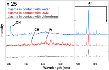 | ||
| Fig. 3 OES measurements of plasma glow in contact with three solvents, recorded at the junction in the microfluidic reactors (blue spot marked 1, Fig. 1). | ||
As a preliminary trial, the optical emission spectrum of the plasma in contact with water was observed at three positions downstream of the junction (Fig. 4).
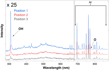 | ||
| Fig. 4 OES measurements of plasma glow in contact with water at positions 1, 2, and 3 as marked on Fig. 1. | ||
As anticipated, the absolute intensity of emission decreases along the channel, but notably the relative peak intensities also change as the plasma composition evolves (Fig. 5). Interestingly the ratio between oxygen and argon species varies with the distance from the junction. This demonstrates that the principle of using distance from the junction as a proxy for time should in future enable us to study the chemical evolution of NTP-driven reactions. These tantalising observations require further study to fully interpret but using the difference in OES spectra as a standard diagnostic tool could help to discover previously unknown trends in plasma species generation in chemical reactions.
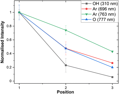 | ||
| Fig. 5 Normalised peak intensities of OH, Ar, and O species observed by OES at positions 1, 2, and 3 (Fig. 1). Error bars represent by standard error taken from repeated OES measurements (n = 3). | ||
Having an on-chip OES device will allow systematic reporting of species arising during plasma contact with the solution. To the best of our knowledge, our microfluidic plasma device is the first to offer such a direct on-chip diagnostic opportunity for NTP in contact with liquid.
These results show that the batch and NTP-MR setup were equally capable of achieving high MB degradation rates at similar energy efficiency. The NTP-MR was capable of faster degradation but at much smaller volumes compared with batch. These results agree with our expectations that the two experimental configurations, batch and NTP-MR, can be used for similar applications. NTP-MR is preferred for small scale reactions and underpinning investigations, allowing in-line analysis of the samples when additional equipment (such as OES) is used. Conversely, the batch set up is able to accommodate higher gas flow rates and thus enables larger scale reactions.
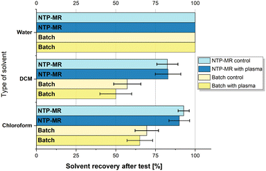
Lastly, the evaporation study was performed, and the results are summarised in Fig. 6; no consistent temperature or colour changes were observed in any of the solvents during or after exposure to NTP. As predicted, the evaporation of DCM and chloroform was noticeable, especially for DCM as it has the highest vapour pressure (350 Torr) compared to water (17.54 Torr) and chloroform (158.4 Torr) and is more volatile. However, the results for both batch and NTP-MR show that the difference between control and plasma experiments is minor and varies between 1 and 10%, which also falls within the error of the experiment. Therefore, these three solvents can be used as a chemical reaction carrier with plasma effectively and safely. When water was treated with plasma using our setup, no evaporation was noted. This is a promising outcome as the water evaporation issue is often highlighted in the literature.10,34
Conclusions
We have successfully manufactured two types of reactors for plasma-assisted chemical reactions. Our initial tests with MB degradation have shown that both platforms can generate active species and transfer them to the liquid phase. We incorporated an atmospheric pressure plasma electrode design to suit microfluidic and batch devices equally. Summarising work on MB degradation between different research groups with similar systems, we highlighted the importance of keeping a consistent and systematic track of parameters used for any NTP chemistry.Achieving the same level of degradation between the platforms shows the potential for compatibility between NTP-MR and batch devices. This approach allows a direct comparison of results between the two devices. This is particularly desirable because we can combine the benefits of both platforms in one study. The batch rig provides the prospect of running experiments on a larger scale, whereas NTP-MR will give a high level of control over the reaction parameters and enable us to incorporate in situ diagnostic tools. The latter will help to understand the mechanisms of plasma chemistry occurring in solutions.
Finally, we used the OES as an in situ diagnostic tool for analysis of the plasma glow at the contact point between plasma and water, chloroform and DCM, pointing at the differences in the plasma–solvent interactions. By measuring at different points along the microfluidic channel we established that different species evolve differently over time. We studied the physical response of solvents to the argon feed NTP, reporting no major changes to temperature or colour. This is particularly interesting for DCM and chloroform as it suggests that it is safe to use these solvents for chemical reactions where water is not desired as a solvent, which enormously expands the applicability of NTP for chemical reactions.
Work is ongoing to carry out and monitor chemical reactions using our safe and easily adjustable platforms. They will be further enhanced with additional diagnostics, and their potential tested with different types of chemistry ranging from organic syntheses to materials functionalisation.
Author contributions
The work was conceptualized and the methodology developed by PR, TLE, JLW, JH, and AGS. The experimental set up was designed, fabricated, and operated by PR with assistance from AD, JLW, TLE and AGS. AD built the power source and batch plasma electrode. Experimental work was carried out by PR. Data were interpreted and the manuscript was prepared for submission by all authors.Conflicts of interest
There are no conflicts to declare.Acknowledgements
The authors thank Cardiff University, the University of Birmingham, the University of York, and the University of Liverpool/EPSRC for funding including a PhD studentship for PR. TLE and AGS gratefully acknowledge receipt of Royal Society University Research Fellowships (201028 and 201168). This work made use of equipment from the Analytical Services/Department of Chemistry at the University of Liverpool as well as shared equipment at the Materials Innovation Factory (MIF) created as part of the UK Research Partnership Innovation Fund (Research England) and co-funded by the Sir Henry Royce Institute.Notes and references
- P. Bruggeman and C. Leys, J. Phys. D: Appl. Phys., 2009, 42, 053001 CrossRef.
- C. Tendero, C. Tixier, P. Tristant, J. Desmaison and P. Leprince, Spectrochim. Acta, Part B, 2006, 61, 2–30 CrossRef.
- S. Xu, H. Chen, C. Hardacre and X. Fan, J. Phys. D: Appl. Phys., 2021, 54, 233001 CrossRef CAS.
- O. Ogunyinka, F. Iza, B. Buckley and H. C. H. Bandulasena, Chem. Eng. Sci., 2021, 240, 116665 CrossRef CAS.
- H. Xu, M. Shaban, S. Wang, A. Alkayal, D. Liu, M. G. Kong, F. Plasser, B. R. Buckley and F. Iza, Chem. Sci., 2021, 12, 13373–13378 RSC.
- P. A. Maitre, M. S. Bieniek and P. N. Kechagiopoulos, Chem. Eng. Sci., 2021, 234, 116399 CrossRef CAS.
- K. Ishikawa and M. Hori, in Plasma Medical Science, Elsevier, 2018, pp. 5–107 Search PubMed.
- T. Takamatsu, K. Uehara, Y. Sasaki, H. Miyahara, Y. Matsumura, A. Iwasawa, N. Ito, T. Azuma, M. Kohno and A. Okino, RSC Adv., 2014, 4, 39901–39905 RSC.
- L. Lin, H. Quoc Pho, L. Zong, S. Li, N. Pourali, E. Rebrov, N. Nghiep Tran, K. Ostrikov and V. Hessel, Chem. Eng. J., 2021, 417, 129355 CrossRef CAS.
- Y. Gorbanev, N. Stehling, D. O'Connell and V. Chechik, Plasma Sources Sci. Technol., 2016, 25, 055017 CrossRef.
- K. Wende, T. Von Woedtke, K. D. Weltmann and S. Bekeschus, Biol. Chem., 2018, 400, 19–38 CrossRef PubMed.
- J. Wengler, S. Ognier, M. Zhang, E. Levernier, C. Guyon, C. Ollivier, L. Fensterbank and M. Tatoulian, React. Chem. Eng., 2018, 3, 930–941 RSC.
- M. A. Malik, A. Ghaffar and S. A. Malik, Plasma Sources Sci. Technol., 2001, 10, 82–91 CrossRef CAS.
- Y. S. Chen, X. S. Zhang, Y. C. Dai and W. K. Yuan, Sep. Purif. Technol., 2004, 34, 5–12 CrossRef CAS.
- J. Ehlbeck, U. Schnabel, M. Polak, J. Winter, T. von Woedtke, R. Brandenburg, T. von dem Hagen and K.-D. Weltmann, J. Phys. D: Appl. Phys., 2011, 44, 013002 CrossRef.
- A. Bogaerts, E. Neyts, R. Gijbels and J. van der Mullen, Spectrochim. Acta, Part B, 2002, 57, 609–658 CrossRef.
- L. Patinglag, D. Sawtell, A. Iles, L. M. Melling and K. J. Shaw, Plasma Chem. Plasma Process., 2019, 39, 561–575 CrossRef CAS.
- Y. L. Cheng, Y. K. Wang, P. Chen, S. B. Deng and R. Ruan, Int. J. Agric. Biol. Eng., 2014, 7, 1–9 Search PubMed.
- T. Desmet, R. Morent, N. De Geyter, C. Leys, E. Schacht and P. Dubruel, Biomacromolecules, 2009, 10, 2351–2378 CrossRef CAS.
- S. Xu, S. Chansai, C. Stere, B. Inceesungvorn, A. Goguet, K. Wangkawong, S. F. R. Taylor, N. Al-Janabi, C. Hardacre, P. A. Martin and X. Fan, Nat. Catal., 2019, 2, 142–148 CrossRef CAS.
- M. Kanno, T. Kitao, T. Ito and K. Terashima, RSC Adv., 2021, 11, 22756–22760 RSC.
- J. He, F. Xu, Y. Tian, C. Li and X. Hou, Chem. Commun., 2020, 56, 5803–5806 RSC.
- H. Chen, Y. Mu, Y. Shao, S. Chansai, S. Xu, C. E. Stere, H. Xiang, R. Zhang, Y. Jiao, C. Hardacre and X. Fan, Catal. Sci. Technol., 2019, 9, 4135–4145 RSC.
- A. Bogaerts, X. Tu, J. C. Whitehead, G. Centi, L. Lefferts, O. Guaitella, F. Azzolina-Jury, H.-H. Kim, A. B. Murphy, W. F. Schneider, T. Nozaki, J. C. Hicks, A. Rousseau, F. Thevenet, A. Khacef and M. Carreon, J. Phys. D: Appl. Phys., 2020, 53, 443001 CrossRef CAS.
- X. Feng, H. Liu, C. He, Z. Shen and T. Wang, Catal. Sci. Technol., 2018, 8, 936–954 RSC.
- P. Attri, M. Yusupov, J. H. Park, L. P. Lingamdinne, J. R. Koduru, M. Shiratani, E. H. Choi and A. Bogaerts, Sci. Rep., 2016, 6, 1–14 Search PubMed.
- Y. Gorbanev, J. Van Der Paal, W. Van Boxem, S. Dewilde and A. Bogaerts, Phys. Chem. Chem. Phys., 2019, 21, 4117–4121 RSC.
- V. Hahn, A. Mikolasch, M. Schmidt, J. E. Neuburger, J. von Langermann, M. Lalk, K. D. Weltmann, T. von Woedtke and J. Kolb, Green Chem., 2022, 24, 7951–7967 RSC.
- Y. J. Liu, X. Z. Jiang and L. Wang, Plasma Chem. Plasma Process., 2007, 27, 496–503 CrossRef CAS.
- Y. Gorbanev, D. O'Connell and V. Chechik, Chem. – Eur. J., 2016, 22, 3496–3505 CrossRef CAS PubMed.
- B. H. Lipshutz, F. Gallou and S. Handa, ACS Sustainable Chem. Eng., 2016, 4, 5838–5849 CrossRef CAS.
- V. Palma, M. Cortese, S. Renda, C. Ruocco, M. Martino and E. Meloni, Nanomaterials, 2020, 10, 1–56 CrossRef.
- S. Samukawa, M. Hori, S. Rauf, K. Tachibana, P. Bruggeman, G. Kroesen, J. C. Whitehead, A. B. Murphy, A. F. Gutsol, S. Starikovskaia, U. Kortshagen, J.-P. Boeuf, T. J. Sommerer, M. J. Kushner, U. Czarnetzki and N. Mason, J. Phys. D: Appl. Phys., 2012, 45, 253001 CrossRef.
- Y. Gorbanev, D. Leifert, A. Studer, D. O'Connell and V. Chechik, Chem. Commun., 2017, 53, 3685–3688 RSC.
- X. Tao, C. Sun, L. Huang, Y. Han and D. Xu, RSC Adv., 2019, 9, 6379–6386 RSC.
- E. Abedelnour, S. Ognier, M. Zhang, L. Schio, O. Venier, J. Cossy and M. Tatoulian, Chem. Commun., 2022, 58, 7281–7284 RSC.
- I. Adamovich, S. Agarwal, E. Ahedo, L. L. Alves, S. Baalrud, N. Babaeva, A. Bogaerts, A. Bourdon, P. J. Bruggeman, C. Canal, E. H. Choi, S. Coulombe, Z. Donkó, D. B. Graves, S. Hamaguchi, D. Hegemann, M. Hori, H.-H. Kim, G. M. W. Kroesen, M. J. Kushner, A. Laricchiuta, X. Li, T. E. Magin, S. Mededovic Thagard, V. Miller, A. B. Murphy, G. S. Oehrlein, N. Puac, R. M. Sankaran, S. Samukawa, M. Shiratani, M. Šimek, N. Tarasenko, K. Terashima, E. Thomas Jr, J. Trieschmann, S. Tsikata, M. M. Turner, I. J. van der Walt, M. C. M. van de Sanden and T. von Woedtke, J. Phys. D: Appl. Phys., 2022, 55, 373001 CrossRef.
- M. F. Thorne, F. Simkovic and A. G. Slater, Sci. Rep., 2019, 9, 1–7 CrossRef CAS PubMed.
- O. Ogunyinka, A. Wright, G. Bolognesi, F. Iza and H. C. H. Bandulasena, Microfluid. Nanofluid., 2020, 24, 13 CrossRef CAS.
- T. Monaghan, M. J. Harding, R. A. Harris, R. J. Friel and S. D. R. Christie, Lab Chip, 2016, 16, 3362–3373 RSC.
- E. Chappel, Appl. Sci., 2020, 10, 8858 CrossRef CAS.
- M. Rafatullah, O. Sulaiman, R. Hashim and A. Ahmad, J. Hazard. Mater., 2010, 177, 70–80 CrossRef CAS PubMed.
- F. Rezaei, Y. Gorbanev, M. Chys, A. Nikiforov, S. W. H. Van Hulle, P. Cos, A. Bogaerts and N. De Geyter, Plasma Processes Polym., 2018, 15, 1700226 CrossRef.
- M. Y. Naz, S. Shukrullah, S. U. Rehman, Y. Khan, A. A. Al-Arainy and R. Meer, Sci. Rep., 2021, 11, 2896 CrossRef CAS PubMed.
- F. Huang, L. Chen, H. Wang and Z. Yan, Chem. Eng. J., 2010, 162, 250–256 CrossRef CAS.
- L. O. de B. Benetoli, B. M. Cadorin, V. Z. Baldissarelli, R. Geremias, I. G. de Souza and N. A. Debacher, J. Hazard. Mater., 2012, 237–238, 55–62 CrossRef CAS.
- A. Krosuri, S. Wu, M. A. Bashir and M. Walquist, J. Water Process. Eng., 2021, 40, 101926 CrossRef.
- Y. Gorbanev, Chem. – Eur. J., 2016, 22, 3496–3505 CrossRef CAS.
Footnote |
| † Electronic supplementary information (ESI) available: Supporting information contains reactor development and 3D-printed prototyping information. Downloads for 3D-printed parts are available via: https://www.thingiverse.com/thing:5448222, https://www.thingiverse.com/thing:5448241 and https://www.thingiverse.com/thing:5874553. See DOI: https://doi.org/10.1039/d3lc00016h |
| This journal is © The Royal Society of Chemistry 2023 |

